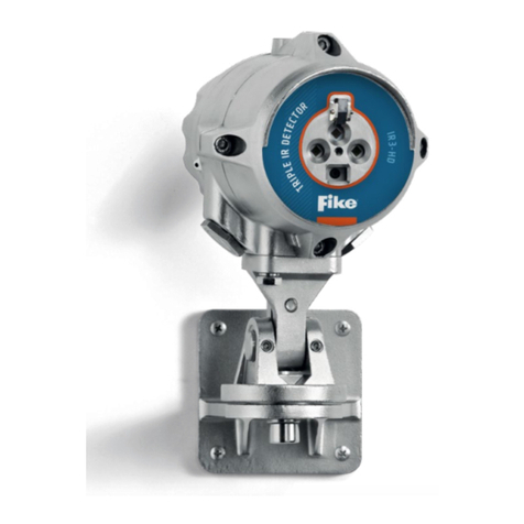
Fike FIK-IR3-H2-HD User manual

- -
FIK-IR3-H2-HD User Manual Doc. No. 06-931.02
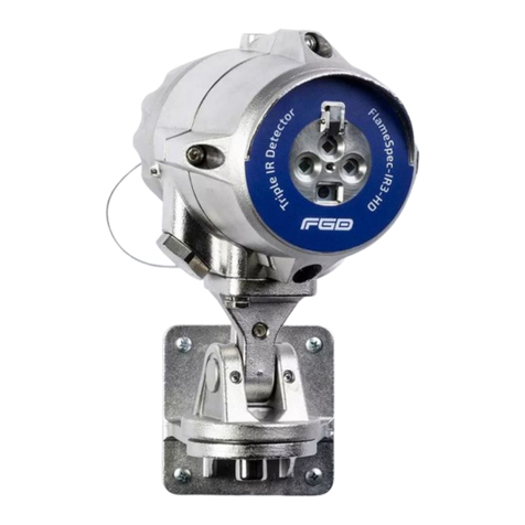
FIK-IR3-H2-HD Triple IR Flame
Detector
www.acornfiresecurity.com

www.acornfiresecurity.com

FIK-IR3-H2-HD User Manual Doc. No. 06-931.02
For more information & Technical support: (800)-979-FIKE (3453) i
FIK-IR3-H2-HD Triple IR Flame Detector User Manual, November 2019
Copyright © Fike Corporation. All rights reserved.
The owner or authorized user of a valid copy of this manual may reproduce this publication
for the purpose of learning to use the specified equipment. No part of this publication may
be reproduced or transmitted for commercial purposes, such as selling copies of this
publication or for providing paid for support services.
The Fike logo is a trademark of Fike Corporation, registered in the U.S. and other countries.
Every effort has been made to ensure that the information in this manual is accurate.
However, Fike is not responsible for any inaccuracy or omission in this document. The
information in this document is subject to change without notice.
www.acornfiresecurity.com

FIK-IR3-H2-HD User Manual Doc. No. 06-931.02
For more information & Technical support: (800)-979-FIKE (3453) ii
Table of Contents
1. Introduction .................................................................................................................... 1
1.1 Key Features ........................................................................................................................1
1. Introduction ...................................................................................................................... 1
1.1 Key Features.............................................................................................................................1
1.2 Model Number Description.......................................................................................................1
1.3 Internal tests ............................................................................................................................1
2Installation......................................................................................................................... 2
2.1 General Considerations.............................................................................................................2
2.2 Preparations for Installation .....................................................................................................3
2.3 Required Tools .........................................................................................................................3
2.4 Certification Instructions...........................................................................................................4
2.5 Installing the Tilt Mount ...........................................................................................................5
2.6 Installing the detector...............................................................................................................6
3Configuration options......................................................................................................... 8
3.1 Sensitivity ................................................................................................................................8
3.2 Ultra-Fast Detection .................................................................................................................9
3.3 Alarm Delay..............................................................................................................................9
3.4 Alarm Latch ..............................................................................................................................9
3.5 Window Heater ........................................................................................................................9
3.6 Video settings...........................................................................................................................9
3.7 Modbus Address.....................................................................................................................10
3.8 Manual BIT – Alarm Output Test .............................................................................................10
4Detector Wiring................................................................................................................ 10
4.1 Wiring Functions:....................................................................................................................11
4.2 Current Output (0-20mA) Wiring.............................................................................................12
4.3 RS-485 Communication Network.............................................................................................13
5Operation......................................................................................................................... 15
5.1 Output Signals ........................................................................................................................15
5.2 Testing ...................................................................................................................................15
www.acornfiresecurity.com

FIK-IR3-H2-HD User Manual Doc. No. 06-931.02
For more information & Technical support: (800)-979-FIKE (3453) iii
5.3 Maintenance ..........................................................................................................................16
5.4 Troubleshooting .....................................................................................................................17
6Specifications ................................................................................................................... 18
6.1 Fire Detection.........................................................................................................................18
6.2 Video functionality .................................................................................................................18
6.3 Electrical Specifications...........................................................................................................18
6.4 Outputs..................................................................................................................................18
6.5 Mechanical Specifications .......................................................................................................19
6.6 Environmental Specifications ..................................................................................................19
6.7 Label Figures ..........................................................................................................................20
6.8 Approvals...............................................................................................................................21
6.9 Electromagnetic Compatibility ................................................................................................21
7.Warranty ......................................................................................................................... 22
Appendix A Response Characteristics.............................................................................. 23
A.1 Response to different fire scenarios ...................................................................................23
A.2False Alarm Immunity........................................................................................................23
www.acornfiresecurity.com

FIK-IR3-H2-HD User Manual Doc. No. 06-931.02
For more information & Technical support: (800)-979-FIKE (3453) iv
List of Figures
Figure 1 - Tilt Mount Base - Rear View.......................................................................................................... 5
Figure 2 - Tilt Mount Base - Side View .......................................................................................................... 6
Figure 3 - Detector on Tilt Mount - Side View............................................................................................... 7
Figure 4 - Source 4 - Wire Scheme ..............................................................................................................12
Figure 5 - Sink 4 - Wire Scheme................................................................................................................... 12
Figure 6 - Source 3 - Wire Scheme ..............................................................................................................13
Figure 7 - Sink 3 - Wire Scheme................................................................................................................... 13
Figure 8 - RS-485 Networking......................................................................................................................14
List of Tables
Table 1 - Detector Configuration Options..................................................................................................... 8
Table 2 - Sensitivity Levels............................................................................................................................. 9
Table 3 - Terminal Connections...................................................................................................................11
Table 4 - Output Signals .............................................................................................................................. 15
Table 5 - Troubleshooting Guide................................................................................................................. 17
www.acornfiresecurity.com

FIK-IR3-H2-HD User Manual Doc. No. 06-931.02
For more information & Technical support: (800)-979-FIKE (3453) 1
1. Introduction
The FIK-IR3-H2-HD flame detector provides ultra-fast response, high performance and reliable detection of
hydrogen (H2) fires.
The detector addresses slow growing fires as well as fast eruptions of fire using improved IR3 technology. The
detector operates in all weather and light conditions. In addition, the detector provides high-definition (HD)
video output of the monitored area with clear imaging of a fire event and of personnel at distances up to 100
ft. (30m).
This allows the rescue team to be aware of the exact situation before entering the hazardous area. The
detector automatically records video of fire event (1 minute pre- and up to 3 minutes post-alarm initiation).
These features, along with the built-in event logger, provide additional means to study the cause and
development of fire events.
1.1 Key Features
•High immunity to false alarm
•Ultra-fast detection mode detection within 40 milliseconds for Hydrogen fireballs or explosions
•Hydrogen flame detection
•High sensitivity – up to 100 ft. (30m)
•HD video output with Automatic HD video recording of fire events
•Data/Event logger – alarms, faults and other relevant events are logged to non-volatile memory
•Ethernet communication – in addition to the standard methods, such as 4-20mA and Modbus
•Built-in-Test (BIT) – Automatic and manual internal self-test of window cleanliness and the overall
operation of the detector
•Window heater to avoid condensation and icing
•Tilt mounting bracket can be connected either above or below the detector.
1.2 Model Number Description
Model No are defined as follows:
•FIK-IR3-H2-HD-AS11 – Detector, HD video output, M25 conduit openings
•FIK-IR3-H2-HD-AS21 – Detector, HD video output, ¾” NPT conduit openings
1.3 Internal tests
During normal operation, the flame detector performs self-tests of its optics, electronics and software.
These include a periodic BIT (Built-In-Test) in which the sensors and window cleanliness are tested. Any
detected fault is indicated as shown in Table 4 (in section 5.1). During “Dirty Window” fault the detection
sensitivity is significantly reduced, while “Fault” refers to critical faults which totally prevent flame
detection.
www.acornfiresecurity.com

FIK-IR3-H2-HD User Manual Doc. No. 06-931.02
For more information & Technical support: (800)-979-FIKE (3453) 2
2Installation
The detector is intended for use as part of a complex system where many detectors and other
devices are integrated with different vendors’ systems and interface communication to a variety
of different types and configuration control units and panels including control of
instrumentations computers. This chapter does not attempt to cover all of the standard
practices and codes of installation. Rather, it emphasizes specific points of consideration and
provides some general rules for qualified personnel. You must always observe special safety
precautions.
2.1 General Considerations
This section includes important information.
To help obtain optimal performance, the detector should be aimed toward the center of the
hazard or area to be monitored and protected ("detection zone") and have, to the extent that is
required, an unobstructed view of the protected area. Whenever possible, the detector face
should be tilted (aimed) down at an angle to prevent the accumulation of dust and dirt.
Do not start an installation until the detector task definition, system configuration, installation
location and coverage considerations have been considered and clearly defined by the relevant
designers.
To ensure optimal performance and an efficient installation that fits your needs and complies
with the requirements, the following guidelines should be addressed:
Sensitivity
To determine the sensitivity level, the following issues should be considered:
•The size of the fire to be detected at the determined distance.
•The type of flammable fuel.
Spacing and Location
Consider the following factors when determining the number of detectors and their
locations in the protected area:
•The size and shape of the protected area
•The nature of the hazards, including materials stored or used and the protected
objects
•The sensitivity of the detectors
•If there are any obstructed lines of sight
•The field of view of the detectors
Environment
•Environmental conditions including but not limited to dust, snow or rain can reduce
the detectors’ sensitivity and require additional maintenance.
www.acornfiresecurity.com

FIK-IR3-H2-HD User Manual Doc. No. 06-931.02
For more information & Technical support: (800)-979-FIKE (3453) 3
Welding
•Arc welding should not be performed within 2 ft. (0.5m) of the detector. It is
recommended that the system be inhibited during welding operations in situations
where the possibility of a false alarm cannot be tolerated.
•Gas welding requires a system inhibit, since the gas torch is an actual fire.
•Arc welding rods can contain organic binder materials in the flux that burn during
the welding operation and are detectable by the device.
•Welding rods with clay binders do not burn and should not be detected. However, a
system inhibit is always recommended, since the material being welded may be
contaminated with organic substances (paint, oil, etc.) that will burn and may be of
the size that should be detected.
2.2 Preparations for Installation
The installation must comply with local regulations and standards applicable to flame detectors
(e.g., NFPA 72) and all local and common engineering practices. It is recommended to consult
with a safety engineer.
The detectors can be installed with the use of general-purpose common tools and equipment.
Prior to installation:
•Verify the appropriate purchase order.
•Record the part and serial numbers of the detectors and the installation date and log.
•Visually inspect the detector prior to installation to make sure it is intact.
•Make sure that you have all the components and tools required to complete the
detector installation readily available before beginning installation. In cases where you
cannot complete the installation in a single session, secure and seal the detectors and
conduits before leaving the site.
•Use color-coded conductors or suitable wire markings or labels for the wiring. You may
use 12 to 20 AWG (2.5 2to 0.35 2) wires for the site wiring. The selection of wire
gauge should be based on the number of detectors used on the same line and the
distance from the control unit, in compliance with specifications.
•Use wire rated for a temperature of at least 111°C, which is 5°C above the rated service
temperature.
2.3 Required Tools
The detector can be installed using general purpose common tools as defined in the following
table:
Tool Function
Hex. KEY 6 mm Vertical alignment
Hex. KEY 10 mm Horizontal alignment
Wrench 13 mm Mounting the detector
Flat Screwdriver 6 mm Ground screw connection
Flat screwdriver 3.5mm Terminal connection
www.acornfiresecurity.com

FIK-IR3-H2-HD User Manual Doc. No. 06-931.02
For more information & Technical support: (800)-979-FIKE (3453) 4
2.4 Certification Instructions
Warning: Do not open the detector, even when isolated, when flammable atmosphere present.
•The equipment may be used in hazardous areas with flammable gasses and vapors with
apparatus groups IIC, IIB and IIA and with temperature classes T1, T2, T3, T4 and T5. See
details of the explosion proof approvals in section 6.7.
•The equipment is certified for use in ambient temperatures in the range of -67°F to
+167°F (-55°C to +75°C) or -67°F to +185°F (-55°C to +85°C) and should not be used in
temperatures outside this range.
•Installation shall be carried out in accordance with the applicable code of practice by
suitably trained personnel.
•Inspection and maintenance of this equipment shall be carried out by suitably trained
personnel in accordance with the applicable code of practice.
•If the equipment is likely to come into contact with corrosive and other harsh
substances, consult with the relevant technical persons to take suitable precautions to
prevent the detector from being adversely affected, thus ensuring that the type of
protection is not compromised.
•Harsh substances: For example, acidic liquids, gases, or solvents that may attack the
lens, metals, seals or polymeric materials.
•Suitable Precautions: For example, regular checks as part of routine inspections or
establishing from the material’s data sheet that it is resistant to specific chemicals.
2.4.1 Specific conditions for use
•The equipment is not intended to be repaired by the user. Repair of this equipment
shall be carried out by the manufacturer in accordance with the applicable code of
practice.
•The flameproof joints are not intended for repair. Contact the manufacturer if the
flameproof joints are damaged.
•Consult the manufacturer for genuine replacement cover and housing to connection
box fasteners. M6x1x18 Hexagonal Socket head fasteners with a minimum of ISO 4762
Grade A4 Class 80 are acceptable alternatives.
•One stopping plug is supplied with the detector and is suitably certified.
•The external earthing connection consists of cable lug with M5x10 stainless steel screw,
the terminals is suitable for connection of a wire of at least 4 2.
•The internal terminals are suitable for connection of a wire equal to or greater than the
power input wiring and at a minimum of 1 2conductor.
www.acornfiresecurity.com

FIK-IR3-H2-HD User Manual Doc. No. 06-931.02
For more information & Technical support: (800)-979-FIKE (3453) 5
2.5Installing the Tilt Mount
The tilt mount enables the detector to be rotated up to 45 degrees (horizontal/vertical) in all
directions. The following installation instructions show how to use it to support the detector
from below (the preferred method). However, with a designated adapter the tilt mount can hold
the detector from above. Other designated adapters may be used to connect the detector to
some other vendors’ tilt mounts (useful when replacing an existing detector).
To install the tilt mount:
a) Place the tilt mount (Fig. 1) in its designated location and secure it with four screws through
four 0.28" (7mm) diameter holes. There are four captive screws with spring washers in the
tilt mount.
The following drawing shows the location of the four holes for the screws and washers.
Figure 1 - Tilt Mount Base - Rear View
www.acornfiresecurity.com

FIK-IR3-H2-HD User Manual Doc. No. 06-931.02
For more information & Technical support: (800)-979-FIKE (3453) 6
The following drawing is a side view of the tilt mount:
Figure 2 - Tilt Mount Base - Side View
2.6 Installing the detector
Use the following steps to connect the detector to the tilt mount, referring to Figure 3:
a) Unpack the detector
b) Place the detector, with its connector or cable pointing down, on the holding plate of the tilt
mount (item 2).
c) Secure the detector by using the two provided screws and spring lock washers (Items 3 and
4).
d) Release the locking screws (Items 5 and 6) in such a way that enables you to rotate the
detector.
e) Point the detector towards the detection area and make certain that the view of the area is
unobstructed.
f) Secure the detector in that position by tightening the locking screws (Items 5 and 6) on the
tilt mount. (Make sure the detector is in the correct position).
The detector is now correctly located, aligned and ready to be connected to the system. Please
refer to section 0 for wiring instructions, and section 0 for a description of the detector’s
configuration settings.
www.acornfiresecurity.com

FIK-IR3-H2-HD User Manual Doc. No. 06-931.02
For more information & Technical support: (800)-979-FIKE (3453) 7
Figure 3 - Detector on Tilt Mount - Side View
ITEM
NO.
ITEM NAME
1 TILT MOUNT ASSEMBLY
2 HOLDING PLATE
3,4 MOUNTING HEX SCREWS M8 AND LOCK WASHERS
5 HEX SOCKET LOCKING SCREW M8
6 HEX SOCKET LOCKING SCREW M12
www.acornfiresecurity.com

FIK-IR3-H2-HD User Manual Doc. No. 06-931.02
For more information & Technical support: (800)-979-FIKE (3453) 8
3Configuration options
Some functions of the detector can be configured using an RS-485 modem connected to a
computer with the “communicator” software. These configuration options are listed in the
following table along with their factory default values.
Table 1 - Detector Configuration Options
Function Options Default Setting
Sensitivity Low, Medium, High, Extreme Medium
Ultra-fast detection Disabled, Enabled Disabled
Alarm delay 0, 5, 10, 20 or 30 seconds 0 seconds (no delay)
Alarm latch Disabled, Enabled Disabled
Window heater Disabled, Enabled Enabled
Video module Disabled, Enabled Enabled
Post alarm video recording duration 1, 2 or 3 minutes 1 minute
Video analog output Disabled, NTSC, PAL Disabled
Modbus address 1 – 247 1
Manual BIT – Alarm Output Test Disabled, Enabled Disabled
•Note: Medium sensitivity setting allows detection of a 32-in Plume of H2 fire at a distance of
66ft (20m).
3.1 Sensitivity
The detector can be configured to one of four sensitivity levels: low, medium, high and extreme.
The following table lists for each sensitivity setting the maximum distance, in which a standard
H2 fire1would be reliably detected.
1A standard fire is defined as a 32-in Plume of H2 fire, with maximum wind speed of 6.5 ft/s (2
m/s).
www.acornfiresecurity.com

FIK-IR3-H2-HD User Manual Doc. No. 06-931.02
For more information & Technical support: (800)-979-FIKE (3453) 9
Table 2 - Sensitivity Levels
Sensitivity level Detection distance in feet (meters)
Low 33 (10)
Medium 66 (20)
High 98 (30)
Extreme 98 (30)
Further details about the response characteristics of the detector at the different sensitivity
settings can be found in Appendix A.
3.2 Ultra-Fast Detection
The ultra-fast detection feature allows detection of fireballs and explosions at 40 milliseconds.
This feature can be disabled or enabled regardless of the alarm delay configuration.
3.3 Alarm Delay
When a flame is detected, the flame detector delays the execution of the alarm outputs by the
configured time period. After this time delay, the detector re-evaluates the situation. If a flame
is still detected the alarm outputs are activated.
3.4 Alarm Latch
If alarm latch is enabled, the detector outputs will remain in alarm mode even after a flame is no
longer detected. To return the detector outputs to normal mode the detector must be powered
down and restarted.
3.5 Window Heater
The detector is equipped with a heater to prevent condensation and icing on the window. If
enabled, the heater is operated automatically depending on temperature.
3.6 Video settings
The detector is equipped with a video camera and processing module. If enabled (“Video
module” setting) the detector provides video outputs and records flame alarm events. The
events are recorded from 1 minute before the flame was detected to 1, 2 or 3 minutes after
(depending on the “post alarm video recording duration” setting).
Digital video output is provided via ethernet and ONVIF Profile S protocol. Composite (analog)
video output is provided in NTSC or PAL format, depending on the “Video analog output”
setting.
www.acornfiresecurity.com

FIK-IR3-H2-HD User Manual Doc. No. 06-931.02
For more information & Technical support: (800)-979-FIKE (3453) 10
3.7 Modbus Address
The detector can communicate with the “communicator” software using a Modbus RTU
compatible protocol on RS-485. This protocol allows for a network of detectors to be connected,
each with a unique Modbus address. The address of the detector can be set to any value in the
range 1–247.
3.8 Manual BIT – Alarm Output Test
When enabled, the alarm outputs are activated when a Manual BIT is initiated. See section 5.2 –
“Testing” for details.
WARNING
Make sure to disable all fire extinguishing actions or alarms connected to the detector when the
manual BIT is initiated and the “Manual BIT – Alarm Output Test” is enabled as the Manual BIT
will set the 0-20mA terminal to 20mA and close the alarm relay.
4Detector Wiring
WARNING
The sensor module in the front half of the detector contains no serviceable components and
should never be opened. The terminal compartment at the back is the only part of the
housing that should be opened by the user.
www.acornfiresecurity.com

FIK-IR3-H2-HD User Manual Doc. No. 06-931.02
For more information & Technical support: (800)-979-FIKE (3453) 11
4.1 Wiring Functions:
The detector has 20 terminals as defined in the following table:
Table 3 - Terminal Connections
Pin # Function Description
Ground Ground (earth) Connected to a screw on the housing exterior.
1 24 VDC (+) Power supply (18-32 VDC)
2 24 VDC (-) Power supply return (0V)
3 0-20mA+ (In)
This output is used for analog 0-20 mA current output
4 0-20mA- (out)
5 Fault Relay
A normally open SPST contact relay, that is energized (closed) when the
detector is in normal operation, and opens in case of fault.
6 Fault Relay COM
7 Alarm Relay (NO) A normally open SPST contact relay, that is open in normal operation,
and closed when fire is detected. This relay can be configured to latch
as described in section (3.4).
8 Alarm Relay COM
9 Analog Video +
Composite (analog) video output
10 Analog Video -
11 24 VDC (+) Power supply (18-32 VDC)
12 24 VDC (-) Power supply return (0V)
13 Manual BIT activation The manual BIT (built-in test) can be initiated by momentarily short
circuiting this terminal and one of the “24 VDC (-)” terminals (2 or 12)”.
See 3.8 Manual BIT – Alarm Output Test for more details.
14 RS 485 (+) RS-485 Modbus communication (used by the “Communicator”
software)
15 RS 485 (-)
16 Ethernet TX+
Ethernet communication, used for digital video (with ONVIF profile S
protocol)
17 Ethernet TX-
18 Ethernet RX+
19 Ethernet RX-
20 Shield This terminal should be left connected to the housing internal ground
screw.
www.acornfiresecurity.com

FIK-IR3-H2-HD User Manual Doc. No. 06-931.02
For more information & Technical support: (800)-979-FIKE (3453) 12
4.2 Current Output (0-20mA) Wiring
The detector’s 0-20mA current output can act as both a source or a sink transmitter and can be
3wire or 4-wire connected.
The following drawing shows how to wire the detector to act as a current source isolated
transmitter (4-wire connection):
Figure 4 - Source 4 - Wire Scheme
The following drawing shows how to wire the detector to act as a current sink isolated
transmitter (4-wire connection):
Figure 5 - Sink 4 - Wire Scheme
Detector
1
2
3
4
VDC24
Return
Return
24VDC
Controller
Power
Detector
1
2
3
4
Power
VDC24
Return
Return
VDC24
Controller
www.acornfiresecurity.com

FIK-IR3-H2-HD User Manual Doc. No. 06-931.02
For more information & Technical support: (800)-979-FIKE (3453) 13
The following drawing shows how to wire the detector to act as a current source non-isolated
transmitter (3-wire connection):
Figure 6 - Source 3 - Wire Scheme
The following drawing shows how to wire the detector to act as a current sink non-isolated
transmitter (3-wire connection):
Figure 7 - Sink 3 - Wire Scheme
4.3 RS-485 Communication Network
Using the RS-485 network capability of the detector and communicator software, it is possible to
connect up to 32 detectors in an addressable system with 4 wires only (2 for power and 2 for
communication). Using repeaters, the number of detectors can be much larger (32 detectors for
each repeater) up to 247 on the same 4 wires. Using the RS-485 network, it is possible to read
each detector’s status (fault, alarm) and to initiate a BIT to each detector individually.
The detector communicates via RS-485 with a Modbus RTU compatible protocol. For more
details on the communication protocol, please consult with FIKE.
Controller
24VDC
Return
Detector
1
2
3
4
11
Controller
24VDC
Return
Detector
1
2
3
12
4
www.acornfiresecurity.com

FIK-IR3-H2-HD User Manual Doc. No. 06-931.02
For more information & Technical support: (800)-979-FIKE (3453) 14
Figure 8 - RS-485 Networking
www.acornfiresecurity.com
Table of contents
Other Fike Security Sensor manuals

Fike
Fike RDU-A-200 User manual

Fike
Fike Twinflex Multipoint 202-0003 User manual

Fike
Fike CIE-A-200 User manual

Fike
Fike FIK-IR3-HD User manual

Fike
Fike FIK-IR3-AS25 User manual
Fike
Fike FIK-RA100 Technical manual

Fike
Fike FIK-W-PHOTO User manual

Fike
Fike FIK-W-PULL-DA User manual

Fike
Fike FIK-FC351 User manual

Fike
Fike 204-0003 Twinflex Multipoint ASD User manual

Fike
Fike CEREX User manual

Fike
Fike FIK-RA1000R Technical manual

Fike
Fike Sita User manual

Fike
Fike 60-1039 User manual

Fike
Fike 323-0001 User manual

Fike
Fike FIK-IR3 User manual

Fike
Fike FIK-UV-IR-HD Series User manual
Fike
Fike FIK-IR3-H2 User manual

Fike
Fike OCELUS Series User manual

Fike
Fike FIK-2351 User manual