manuals.online logo
Brands
  1. Home
  2. •
  3. Brands
  4. •
  5. Fike
  6. •
  7. Security Sensor
  8. •
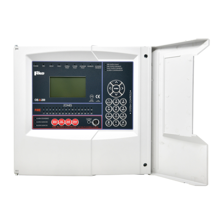
  9. Fike RDU-A-200 User manual

Fike RDU-A-200 User manual

This document is only intended to be a guideline and is not applicable to all
situations. Information subject to full disclaimer at www.ke.com/disclaimer
Document No. 26-1773-1
Subject to change
Do not attempt to use this equipment until you have fully read and understood this guide.
RDU-A-200
Quick Start Guide
A knowledge of BS5839: Pt 1: 2017: Fire Detection and Alarm Systems for Buildings is essential.
It is strongly recommended that a suitably qualied and competent person is consulted in connection with the Fire Alarm System
design and that the entire system is commissioned in accordance with the current national standards and specications.
Equipment Guarantee
The equipment carries no warranty unless the system is installed, commissioned and serviced in accordance with the manual and the
relevant standards by a suitably qualied and competent person or organisation.
Access Level Description Shift LED Key Operation Default code
0 – NORM Normal OFF NO N/A
1 – USER User ON YES 8737
2 – SUPR Supervisor SLOW FLASH NO 7877
3 – ENGR Engineer FAST FLASH NO 3647
Surface Mounting
The three mounting holes should be used to se-
cure the cabinet to a solid wall using suitable
screws of at least 50mm in length. Ensure that a
minimum gap of 50mm is left between the sides
of the back box and any wall or projection (such
as another box).
http://www.ke.co.uk/
resource-downloads/addressable/
Document No. 26-1773-1
Subject to change
Fire Alarm Controls
The menus on repeater panels are exactly the same as the menus on a control panel. However most of the controls are not relevant
for repeater panels so will give the message ‘ NOT AVAILABLE ON RDU’.
The main Fire Alarm Controls may be enabled by turning the key switch to the “controls enabled” position,
or by entering a valid Access code (See page 1).
The menus may be navigated in one of two ways as required:
1. Use the UP / DOWN keys to move the highlighted selection and press ENTER to select the chosen one.
2. Enter the desired option number and press ENTER to select it.
Press the Esc key to exit to the previous menu.
Mains Supply & Batteries
The repeater panel 230V AC supply requires xed wiring between 1 mm2 and 2.5 mm2, a 3 a m p f u s e d
un-switched spur with local isolation. The mains supply should be dedicated to the repeater panel and should
be clearly labelled ‘FIRE ALARM: DO NOT SWITCH OFF’ at all isolation points.
The repeater panel requires 2 x 12V 7Ah sealed lead acid batteries. The batteries should be connected in
series using the connection leads supplied. We recommend the use of type Yuasa NP7-12 (FR) or other
equivalent approved type.
Do not use smaller capacity batteries on this system, smaller ones will be overcharged and the service life will
be reduced.
Using di󰀨erent capacity or type of batteries could also invalidate any warranty.
Note that batteries are electrically live at all times and great care should be taken to ensure that the terminals
are never presented with a short circuit. Care should be taken at all times, especially during transit, installation
and normal use.
Use caution as there is a risk of explosion if the batteries are replaced by an incorrect type.
Batteries no longer required should be disposed of in a
safe and environmentally friendly manner by the battery
manufacturer or a suitable recycling service. They
should never be incinerated or placed in normal rubbish
collection facilities. Dispose of used batteries according
to the instructions. F3.15A 20MM
GLASS FUSE BOTTOM OF BOARD
--
BATT
+
-
++
SCRN
+
-
SCRN
32V FROM PSU MODULE
32V
INPUT
Document No. 26-1773-1
Subject to change
Document No. 26-1773-1
Subject to change
Commissioning
The commissioning process regarding the loops and devices is covered in the Control Panel Engineering & Commissioning Manuals.
The repeater panel commissioning is only concerned with the functionality of the repeater panel itself.
Communications between the panel and repeater is via a multi-drop RS-485 Peripheral Bus.
2-core 1.5mm2 screened re resistant cable (i.e. FP200, Firetu󰀨, Firecell) cable should be used for communications to the repeater.
The maximum total cable length from the control panel to a repeater is 500 metres.
Up to 8 repeaters can be used but they must all be within the maximum 500 metres cable length and are wired + to +, - to -, the screen
must be connected to the control panel at one end only using the terminals provided. Terminate the unused end in a connector block
as shown below and so on up to the maximum of 8 repeaters.
The peripheral bus must be run from the panel to the rst repeater then the second repeater and so on; the peripheral bus must not
be spurred from one point.
The jumpers are tted to impedance match the cable with the driver ICs & prevent signal reections down the cable.
The commissioning engineer will require the peripheral bus continuity and insulation readings, along with correctly marked ‘as-wired’
drawings and completed conguration sheets in order to commission the repeater panel.
The system conguration must be downloaded into the repeater panel using the CIE-A-200 OSP programming software using a USB
lead to link to a computer. This procedure is exactly the same for the repeater panel as has been done on the main control panel.
However, the conguration must be the repeater panel conguration (including the panel type being repeater and the address being
the repeater address) and not the control panel conguration.
NOTE: It is imperative that the correct version of OSP is used to match your version of repeater panel. The use of an
incompatible version may result in incorrect operation of the repeater panel.
When the system conguration has been downloaded into the repeater panel, the commissioning engineer should verify that all the
re alarm system events are correctly reported on the repeater panel and the repeater panel controls operate correctly.
This will involve testing the system and therefore can be combined with the overall system commissioning process.
If the repeater panel has been tted as a system upgrade then a full system test should
be carried out to verify that all the re alarm system events are correctly reported on the
repeater panel and the repeater panel controls operate correctly.
SCRN SCRN
PB_1
--
++
PB_1
PANEL 1 PANEL 2
EOL
NOT EOL
RDU
EOL
END OF
LINE RDU
MOVE JUMPER
Document No. 26-1773-1
Subject to change
Fike Safety Technology Ltd | Unit 31 Springvale | Cwmbran | NP44 5BD
Tel: 01633 865 558 | Email: fstinfo@ke.com
Technical Support
Contact your supplier for technical support on this product.
Due to the complexity and inherent importance of a life risk type system, training on this equipment is essential, and commissioning should only be
carried out by competent persons. Fike cannot guarantee the operation of any equipment unless all documented instructions are complied with,
without variation. This unit complies with the EMC directive.
Fike’s policy is one of continual improvement and the right to change a specication at any time without notice is reserved.
Whilst every care has been taken to ensure that the contents of this document are correct at time of publication, Fike shall be under no liability what-
soever in respect of such contents. E&OE.
Fike and Fike Corporation are registered trademarks of Fike Corporation and its subsidiaries. All other trademarks, trade names or company names
referenced herein are the property of their respective owners.
Technical Information
Mains T4A Time Delayed 20mm Ceramic (in mains terminal block)
Battery Charger 700mA current limiter
Battery (reverse polarity) F3.15A Fast Blow 20mm (in line with battery leads) Glass
Dimensions 353mm x 333mm x 117mm
Cable Type 2 core 1.5mm2 screened re rated cable
Operating Voltage 21-33v
Operating Current Quiescent @ 32v 30mA
Operating Current Max @ 32v 60mA
Communications Multi-drop RS-485
Total Peripheral Bus Length 500m
IP Rating / Operating Temperature IP30 / +5oC to +40oC
Max Number of Repeaters per
Control Panel
8

Other Fike Security Sensor manuals

Fike FIK-RA100 Technical manual

Fike

Fike FIK-RA100 Technical manual

Fike FIK-IR3 User manual

Fike

Fike FIK-IR3 User manual

Fike FIK-IR3-H2-HD User manual

Fike

Fike FIK-IR3-H2-HD User manual

Fike FIK-UV-IR-HD Series User manual

Fike

Fike FIK-UV-IR-HD Series User manual

Fike Twinflex Multipoint 202-0003 User manual

Fike

Fike Twinflex Multipoint 202-0003 User manual

Fike FIK-IR3-AS25 User manual

Fike

Fike FIK-IR3-AS25 User manual

Fike FIK-FC351 User manual

Fike

Fike FIK-FC351 User manual

Fike FIK-RA1000R Technical manual

Fike

Fike FIK-RA1000R Technical manual

Fike FIK-W-PULL-DA User manual

Fike

Fike FIK-W-PULL-DA User manual

Fike FIK-W-PHOTO User manual

Fike

Fike FIK-W-PHOTO User manual

Fike 204-0003 Twinflex Multipoint ASD User manual

Fike

Fike 204-0003 Twinflex Multipoint ASD User manual

Fike 60-1039 User manual

Fike

Fike 60-1039 User manual

Fike CEREX User manual

Fike

Fike CEREX User manual

Fike VESDA LaserCOMPACT VLC-500 User manual

Fike

Fike VESDA LaserCOMPACT VLC-500 User manual

Fike 323-0001 User manual

Fike

Fike 323-0001 User manual

Fike 203-0003 User manual

Fike

Fike 203-0003 User manual

Fike FIK-IR3-H2 User manual

Fike

Fike FIK-IR3-H2 User manual

Fike CIE-A-200 User manual

Fike

Fike CIE-A-200 User manual

Fike FIK-IR3-HD User manual

Fike

Fike FIK-IR3-HD User manual

Fike Sita User manual

Fike

Fike Sita User manual

Fike OCELUS Series User manual

Fike

Fike OCELUS Series User manual

Fike FIK-2351 User manual

Fike

Fike FIK-2351 User manual

Popular Security Sensor manuals by other brands

STEINEL PROFESSIONAL IS 345 MX PF manual

STEINEL PROFESSIONAL

STEINEL PROFESSIONAL IS 345 MX PF manual

Renishaw TRS2 installation guide

Renishaw

Renishaw TRS2 installation guide

EVERSPRING HSP01-0 Installation and operating instructions

EVERSPRING

EVERSPRING HSP01-0 Installation and operating instructions

Climax Technology IR-29 manual

Climax Technology

Climax Technology IR-29 manual

Oxford PRECISION OXD-516-1336M Operator's manual

Oxford PRECISION

Oxford PRECISION OXD-516-1336M Operator's manual

Seitron RGDCOHMP11SE manual

Seitron

Seitron RGDCOHMP11SE manual

LEGRAND CP Electronics EBDSPIR-L3 installation guide

LEGRAND

LEGRAND CP Electronics EBDSPIR-L3 installation guide

Vaxcel T0270 Assembly and installation instructions

Vaxcel

Vaxcel T0270 Assembly and installation instructions

Rielta C.Nord CN-PIR installation guide

Rielta

Rielta C.Nord CN-PIR installation guide

GTV PARIS AE-SRC812-MIN2 quick start guide

GTV

GTV PARIS AE-SRC812-MIN2 quick start guide

EMP-Centauri P.117 instruction manual

EMP-Centauri

EMP-Centauri P.117 instruction manual

Gait up Physilog 5 user manual

Gait up

Gait up Physilog 5 user manual

Niko SERVODAN 41-771 user manual

Niko

Niko SERVODAN 41-771 user manual

Tattletale GLASS BREAK DETECTOR quick start guide

Tattletale

Tattletale GLASS BREAK DETECTOR quick start guide

Steren SEG-060 instruction manual

Steren

Steren SEG-060 instruction manual

Wenglor P1KK008 operating instructions

Wenglor

Wenglor P1KK008 operating instructions

LG 17HK701G-WV manual

LG

LG 17HK701G-WV manual

koban KDP-DALI 01 manual

koban

koban KDP-DALI 01 manual

manuals.online logo
manuals.online logoBrands
  • About & Mission
  • Contact us
  • Privacy Policy
  • Terms and Conditions

Copyright 2025 Manuals.Online. All Rights Reserved.