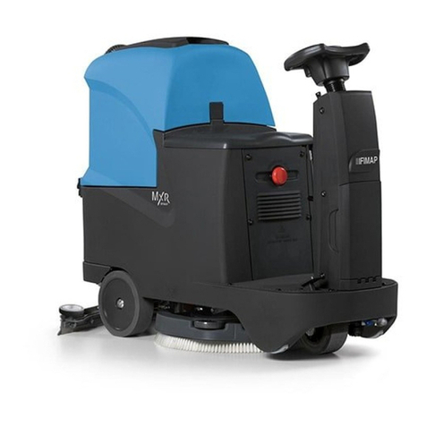
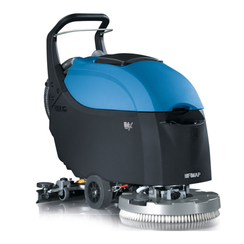
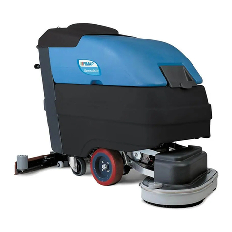
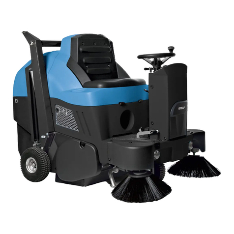
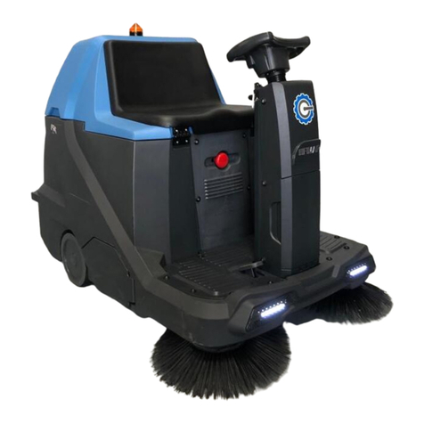
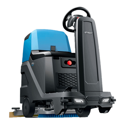
Fimap MAGNA 85 BS Reference guide

ADJUSTMENT
AND
INSPECTION
MAGNA 85 – 100 BS
Doc.
Issued 12/2006
Rev. 00
Pag. 1 di 18
ADJUSTMENT AND INSPECTION
READ THE OPERATING AND MAINTENANCE MANUAL
Service of the Console
The console allows to:
-
-
-
set the chopper card for a personalised behaviour of the traction motor
read the type of the alarm for a correct and easy trouble shooting
test the different electric values and the state of the electric circuit relative to the traction
Use of the Console
The use of the instrument is very easy and comparable to one of the most common electronic devices
(such as mobile phones).
The sequence to follow always for the console connection is:
1. SWITCH OFF THE GENERAL KEY of the machine
2. take off the connector E from the chopper
3. connect the console in place of the connector E. If the operation connection results to be difficult,
check that the connector is positioned in the correct direction.
4. switch on the key and work with the console
5. quit from all the programs (main menu of the ignition) and SWITCH OFF THE GENERAL KEY of the
machine
6. disconnect the console connector and plug in the connector E
THE WRONG OPERATION SEQUENCE CAN EASILY COMPROMISE
THE FUNCTIONALITY OF THE CHOPPER CARD OR OF THE CONSOLE
CHOPPER CARD TERMINAL
CONSOLE TERMINAL

ADJUSTMENT
AND
INSPECTION
MAGNA 85 – 100 BS
Doc.
Issued 12/2006
Rev. 00
Pag. 2 di 18
Menu of the Console
HEADING: the features of the console and of the chopper card: voltage and maximum current of the
chopper card, the working hours of the chopper card.
PARAMETER CHANGE: in this menu the parameters can be changed to personalise the machine. The
parameters that can be modified are : CUT BACK SPEED 1 (minimum speed machine) and the CUT BACK
SPEED 2 (medium speed machine). All the other parameters are decided in Fimap and they are
related to the traction motor. It is forbidden to change them without previous Fimap
authorisation.
TESTER: the quantities of the electric characteristics (traction motor voltage, state of power switch =
closed/open ...) are showed in this menu.
SAVE: this permits, once the parameters have been changed, to enter the new setting in a storage
location of the console.
RESTORE: this permits to restore on the chopper card a parameter setting which has been entered in
the console.
ALARMS: indicates a list of the last five alarms occurred on the machine. According to the alarm a
specific corrective action is adopted (see following paragraph).
PROGRAM VACC: this section is used to teach the chopper about the potentiometer which is assembled
on the machine. It is an operation to be carried when there is the alarm Vacc not ok, when the
pedal accelerator is being replaced, when the chopper card is being replaced. A wrong relation
between the potentiometer and the chopper card causes the machine stop.

ADJUSTMENT
AND
INSPECTION
MAGNA 85 – 100 BS
Doc.
Issued 12/2006
Rev. 00
Pag. 3 di 18
Flow chart of the console
HEADING
PROGRAM
TESTER
enter
enter
LIST OF PARAMETERS
ROLL to select
DO YOU WANT TO
SAVE DATA ?
out PARAM SET to change
enter
out
ENTER = change
OUT
=
no change
enter
TEST LIST OF VALUES
to test
R
O
L
L
This menù has
not to be
modified
ROLL to select
PROGRAM
VACC
enter
out
Program for setting
pedal accelerator
MOTOR data
enter
out
R
O
L
L ente
r
out
enter
SAVE
enter
out
LIST OF free locations
Write on on a FREE
location
enter
enter
RESTORE
enter
out
LIST OF locations
(programs) to load on
the chopper card
Enter: Are you sure ?
ENTER = restore
out
Enter: Are you sure ?
ENTER = save
OUT= no save
OUT= no restore
ALARMS
Out
List of the last 5
alarms occurred
enter / en
ter
Out: Are you sure?
ENTER = change
OUT= no change
This menù has
not to be
modified

ADJUSTMENT
AND
INSPECTION
MAGNA 85 – 100 BS
Doc.
Issued 12/2006
Rev. 00
Pag. 4 di 18
Alarms and Decoder
The chopper card visualises an anomaly on two levels of information
1. through a red alarm led which blinks for a quantity of times relative to the type of anomaly
2. through a message on the console that specifies more details on the nature of the anomaly.
Following table reports for each alarm the possible anomaly and of how to proceed on the machine.
DIAGNOSIS LIST ALARMS
(for better understanding of the list refer also to the electrical layout)
Number of
blinkings MESSAGE NOTES
1 WATCH DOG
The test of self-diagnosis of the chopper card carried
out both on rest as in drive verifies an anomaly
Possible causes
-the logic of the chopper card is damaged
Actions
-replace the chopper card
1 EEPROM DATA KO
The data of the hourmeter inside the chopper card
Actions
-switch off and on again the key. If the problem will be
solved the counter will be reset.
1 EEPROM OFF LINE
The data of the hourmeter and of the alarm stored in
the chopper card are not correct
Actions
-
-
switch off and on again the key. If the problem persists
replace the chopper card
if the problem will be solved the data will be cancelled
1 EEPROM PAR KO
The memory of the chopper card has lost the
adjustment and operation data
Actions
-
-
switch off and on again the key. If the problem persists
replace the chopper card
if the problem will be solved the data will be replaced with
the standard data

ADJUSTMENT
AND
INSPECTION
MAGNA 85 – 100 BS
Doc.
Issued 12/2006
Rev. 00
Pag. 5 di 18
Number of
blinkings MESSAGE NOTES
2 INCORRECT START
Incorrect starting sequence
Possible causes
-
-
-
error in the sequence Key/drive selection made by the
operator
the micro pedal and/or micro drive are stuck
wiring not correct
Actions
check the starting sequence which is:
-
-
-
-
-
switch on the key
select drive (forwards/backwards)
press the accelerator
check that the drive microswitch and the manipulator
forward/backward traverse selector do not have the
contacts stuck and that they work correctly
verify the continuity of the circuit that connects the micro
drive pedal, the chopper card and the drive manipulator.
3 VMN LOW
The first check recognises a voltage VMN lower than the
25% of the battery voltage
Possible causes
-
-wrong connections on the motor
motor current leakage to the ground
Actions
-
-
-
check that the motor terminals are well isolated from the
motor casing both inside and outside the motor. Verify that
there is not dirt that causes current leakage between the
terminals and the motor body
verify that the motor is not wet and in case dry with an air
flow
check that the connections on the motor and on the
chopper card are correct (verify the type of traction motor
assembled, the correct wiring and the connections on the
chopper VMN, positive and negative)
if the problem persists replace first the chopper card and, if
necessary, also the motor
3 VMN HIGH
Starting test check possible faults on the power circuit
branch .
Possible causes
-
-chopper power branch damaged
MOSFET logic control damaged
Action
-replace the chopper card
ADJUSTMENT
AND
INSPECTION
MAGNA 85 – 100 BS
Doc.
Issued 12/2006
Rev. 00
Pag. 6 di 18
4 VACC NOT OK
The chopper card recognizes an anomaly in the mechanical
stroke of the accelerator
Possible causes
-the operator switched on the machine with the
accelerator pressed down or he pressed down the
accelerator before the selection of forward or backward
traverse
-
-
-
-
-
the seat microswitch does not work
the potentiometer and/or the chopper card has been
changed and the relating values between the two
components are to be re-programmed
a cable between the potentiometer and the chopper card is
interrupted
the potentiometer is faulty
the PROGRAM VACC (see chapter Adjustment and
Inspection) has not been carried out correctly
Actions
- check the correct sequence to get traverse
-
-
check the continuity of connections between the
potentiometer accelerator and chopper card
re-program the chopper card with PROGRAM VACC (see
chapter Adjustment and Inspection)
- check the functionality of the potentiometer (it could be
broken) and replace it if necessary (re-programming then
the chopper card)
5 I HIGH AT STAND
The chopper card tests if on rest the signal of the
current is zero. Otherwise, it blocks the traction
Possible causes
-
-defective current sensor
fault in the feedback circuits, or in the logic or on the
chopper card
Actions
- replace the chopper card
6 NPOT NOT OK
Test on working condition: the negative point brings is
at a wrong
Possible causes
-the potentiometer is not well connected to the chopper card
-potentiometer defected
Actions
-
-check the good connections potentiometer – chopper card
check the potentiometer efficiency

ADJUSTMENT
AND
INSPECTION
MAGNA 85 – 100 BS
Doc.
Issued 12/2006
Rev. 00
Pag. 7 di 18
7 TH PROTECTION
The chopper card works out of the temperature range
(-30°C + 70°C)
Possible causes
-
-chopper card faulty
the machine runs in braking condition and the chopper gets
overheated
Actions
-check the temperature of the site where the machine works
-check the consumption of the traction motor
8 DRIVER SHORTED
COIL SHORTED
The driver that controls the driver power switch do not
operate properly
Possible causes
-the driver is defected
Actions
-replace the chopper card
32
permanent
blink
BATTERY LOW
Battery level too low: the chopper card cuts the power to the
traction motor for its safeguard
Actions
check the charge of the batteries
check the cleanliness and the good connections on the
chopper card of the cable that come from the battery
permanent
switched on FORW BACK
The alarm is indicated when both the forward and backward
requests are activated simultaneously
Possible causes
-
-wiring not correct
microswitch forward or backward stuck
Actions
-
-
-
check the correct functionality of the contacts of the
manipulator
verify the wiring relative to the manipulator
if the defect persists replace the chopper card
ADJUSTMENT
AND
INSPECTION
MAGNA 85 – 100 BS
Doc.
Issued 12/2006
Rev. 00
Pag. 8 di 18
ADJUSTMENT FOR MOTORWHEEL
A1
A2D1
79
108
D2
A
A
S
7
8S
10
9
CIMA
METALROTA
ATTENTION : In case of wrong direction, change the cable 7 and 8.
CHOPPER HO
MAGNA 85 - 100 CIMA WHEEL METALROTA
WHEEL
ACCELERATION DELAY 4 4
BRAKING 1 2
RELEASE BRAKING 2 4
CUTBACK SPEED 1 3 3
CUTBACK SPEED 2 6 6
COMPENSATION 9 9
CREEP SPEED 1 3
TRACTION IMAX 3 3
MAX SPEED FORWARD 9 9
MAX SPEED BACKWARD 7 7
SPEED LIMIT BRAKING 3 3

ADJUSTMENT
AND
INSPECTION
MAGNA 85 – 100 BS
Doc.
Issued 12/2006
Rev. 00
Pag. 9 di 18
Adjustment using the console
Inserting the console
1. Check that all switches are off.
2. Lift the front wheel on the safety stand.
3. Insert the console into its connector with the key off.
4. Turn on using the key.
5. Either “HO AUTOSTOP V1.0 36V 200A 00000” or “*Alarm* abcdef …” will appear when it
starts up
6. Press seat.
7. Press ENTER to access the main menu.
Programming the chopper Console Display
1. Press ENTER to access the main menu.
2. The first item appears: “PROGRAM” = CHANGE PARAMETERS.
3. Press ENTER and check, scrolling with ROLL, if programming values
comply with the previous table.
* SELECT MENU *
1- PROGRAM
4. At the end press OUT and confirm with ENTER (in reply to “DO YOU
WANT TO SAVE DATA?”) if a parameter has been changed (using the
PARAM SET push-buttons on the console).
WARNING: SAFETY PARAMETERS CANNOT BE VARIED, SUCH AS
ACCELERATION, BRAKING, ETC.
ONLY SPEED CUTBACKS CAN BE VARIED (CUTBACK SPEEDS 1 AND
2).
5. If the chopper memory is lost use ROLL to select “RESTORE” =
REPROGRAM CHOPPER PARAMETERS: * SELECT MENU *
4- RESTORE
6. Press ENTER.
7. The PROGRAM 01 code appears (use ROLL to select the desired
PROGRAM): * SELECT PROGRAM *
PROGRAM 01
8. Press ENTER to confirm loading the program.
9. A request for confirmation appears, press ENTER = YES, OUT= NO : ARE YOU
SURE?
10. Press ENTER to confirm the loading procedure.
11. The stand-by message appears while loading the parameters: WAIT!
12. At the end the following message returns: * SELECT MENU *
4- RESTORE

ADJUSTMENT
AND
INSPECTION
MAGNA 85 – 100 BS
Doc.
Issued 12/2006
Rev. 00
Pag. 10 di 18
Acquiring accelerator pedal travel Console Display
1. Use ROLL to select: * SELECT MENU *
6- PROGRAM VACC
2. Press ENTER to display: FORW BACK
4.99 4.99
3. Press ENTER to zero the values: FORW BACK
0.0 0.0
3. Engage the 3rd forward gear and slowly press the pedal all the way
down without stopping and values of the following type will
appear:
FORW BACK
4.84 0.0
4. Repeat the procedure with reverse gear: FORW BACK
4.84 4.84
5. Press ENTER to display: ARE YOU
SURE?
6. Press ENTER to confirm and go back to the initial heading: * SELECT MENU *
6- PROGRAM VACC
Tester
1. WARNING: make sure the front wheel is lifted on the safety
stand.
2. Use ROLL to select: * SELECT MENU *
2- TESTER
3. Press ENTER and various parameters of the following types
appear: VMN
VMN > 30%
4. Use ROLL to select: BATTERY
VOLT=36 36V
5. Use ROLL to select: MOTOR VOLTAGE
VOLT = 00.0
6. Engage forward gear and 3rd gear and the following will appear: MOTOR VOLTAGE
VOLT = 26
7. Select 2nd gear and rotate the wheel at maximum speed and the
following will appear:
MOTOR VOLTAGE
VOLT = 21 - 22
(or similar values)

ADJUSTMENT
AND
INSPECTION
MAGNA 85 – 100 BS
Doc.
Issued 12/2006
Rev. 00
Pag. 11 di 18
Tester
8. Select 1st gear and rotate the wheel at maximum speed and the
following should appear:
MOTOR VOLTAGE
VOLT = 13 – 14
(or similar values)
9. If speed cutbacks are inverted check the position of the blue and
brown wires on the speed switch: the blue wire must be behind
the brown wire.
10. Engage reverse gear, press the pedal all the way down and the
following will appear:
MOTOR VOLTAGE
VOLT = 26 – 30
(or similar values)
11. Press OUT.
10. If necessary select with ROLL : * SELECT MENU *
1- PROGRAM
12. Turn off the main key and detach the outlet from the chopper
console.
13. Remove the safety stand.
Motor data
1. Use ROLL to select: * SELECT MENU *
7- MOTOR DATA
2. Press ENTER to access the “MOTOR DATA” = ACQUIRE DRIVE
MOTOR DATA function. If the value "50" appears then things are
correct. Otherwise you can re-program to approach “50” by
pressing the brake more or less the moment this is requested by
the chopper.
BLOCK MOTOR PLEASE
3. Press ENTER to prepare the acquisition procedure.
4. Press the brake pedal and keep it pressed.
Press ENTER to display: INSERT FORWARD
DIRECTION
5. Engage forward gear with the joystick and press the drive pedal all
the way down (at this time the machine should not move).
6. Press OUT and the following will appear: ARE YOU SURE?
7. Press ENTER and the following will appear: WAIT!
8. Press OUT to completely exit from programming mode.
9. Turn the main key off.
10. Detach the console outlet from the chopper.

ADJUSTMENT
AND
INSPECTION
MAGNA 85 – 100 BS
Doc.
Issued 12/2006
Rev. 00
Pag. 12 di 18
Microswitches of the squeegee
1. Release the screw that fix the cam on the actuator shaft
2. Lift up the squeegee and check to have the distance between
the upper part of the squeegee support and the floor about
160mm
3. turn the cam until the internal microswitch
( the one
nearest to the actuator) is activated
4. Block the cam in that position.
The other microswitch will be automatically correctly activated
when the squeegee is lowered.
Adjustment of the microswitch of the basement with cylindrical brushes
1. Remove the front and lateral panel.
2. Place both microswitches, so that there remains a play of 1
mm between the casing and the level with the wheel, when
the cam is pushes on the lever.
3. Check, if with min. brush pressure (is achieved, when the
hand-pressure rod is pressed at the first step ), the upper
side of the bracket is height 470mm from the floor, adjust
the microswitch for the lowering of the brush base by adapting
the microswitch support rod. Carry out another test of the
movement and check the measurements.
4. Adjustment of the support lifting microswitch
of the
basement, so that the guide wheels right and left rest
lightly pressed on the frame and the basement does not
oscillate during displacement of the basement.
470mm

ADJUSTMENT
AND
INSPECTION
MAGNA 85 – 100 BS
Doc.
Issued 12/2006
Rev. 00
Pag. 13 di 18
5. Check, if the lifted brush unit, moves freely to the left after
bumps.
Adjustments and checks of the cylindrical brush base
1. Pressure adjustment for the cylindrical brushes: let down the
cylindrical brush unit adjust the ring nut to a spring length
between 210 mm
2. Fix the ring nut.
SCREW THE RING NUT TO REDUCE THE PRESSURE
3. Inclination adjustment of the cylindrical brush base: if
necessary (current consumption of the motors or unequal
brush consumption) adjust through the excentrical
Bushings on the lower left and right arms:
unscrew the adjuster nut;
loosen the screws;
turn the bushings until the evenness adjust. of the basement;
fix the screws and the adjuster nuts.
Calibration of the ammeter card brush motor

1. Insert the ammeter pincers on the current supply cable
(cable n° 20) of the front brush motor.
2. Let down the basement gradually, with max. pressure, on
rough floor.
3. Push the brush switch, so that the brushes rotate.
4. When you achieve 38-40 A, both control light should start to
blink; if the calibration is different adjust Trimmer Isx
(ampere) and keep the current consumption of the motor
constant according the indicated values.
5. Increase the pressure until the pincer indicates 44-46 A
and
check if the card intervene after 14-18 blinking signals (the
left lamp remains switched on permanently) and switches off
the motor; in case of differences, switch of the general key
and repeat the process after the adjustment of Trimmer Tsx
(time) on the card, so that the right intervention time is
achieved.
Isx
tsx
Id
x
td
x

ADJUSTMENT
AND
INSPECTION
MAGNA 85 – 100 BS
Doc.
Issued 12/2006
Rev. 00
Pag. 14 di 18
6. Repeat the process on the back motor cable (cable N° 20A):
Trimmer Idx and Trimmer Tdx (after the intervention of the
card, the right lamp remains switched on).
7. Block the trimmers with anti loosening seal.
8. Check under working conditions if both motors have a similar
current consumption with a max. tolerance difference of 2-4
ampere. If you get substantial differences change the
inclination of the brush base (see point 3 of the adjustments
and checks of the brush base unit).
Adjustment of the card for the delay (floating switch)
3. Switch on the vac motor and lift manually the floating
switch and check to have a delay of about 4 sec for the
stop of the motor. In case adjust the trimmer on the card.
4. Block the trimmer .
Adjustment of the lateral bars
1. Adjust the front part of the lateral bars: Adjustment of the
knobs until the rubber touches slightly the floor.
2. Adjustment of the back part of the lateral bars: Adjust the
lock nut, so that the rubber is slightly bended; block it with
the clip.

ADJUSTMENT
AND
INSPECTION
MAGNA 85 – 100 BS
Doc.
Issued 12/2006
Rev. 00
Pag. 15 di 18
Squeegee adjustment
1. Loosen the block wheels.
2. Lift the squeegee wheels from the floor.
3. In this condition adjust the rubber squeegee inclination by
operating on the knob (loosen first the lock nut). The rubber
on the floor has to be bent uniformly along all the length of
the squeegee
4. Screw down the wheels and lift the squeegee from the
ground: the inclination of the rubber should be about 45°
5. Lock the wheels.
45°
Check and adjustment of the brake
1. To adjust the correct stroke of the brake pedal (two or three
releases for the parking condition) operate an adjustment on
the relative forks
2. Check the oil level in the tank . In case add oil D.O.T. 4 for
brake systems.
3. Check if the right brake stops in the same way of the left one .
In case adjust again the forks.
Adjustment of the steering
1. Adjust the right tension of the chain by acting upon the chain
tightening (screw M8)

ADJUSTMENT
AND
INSPECTION
MAGNA 85 – 100 BS
Doc.
Issued 12/2006
Rev. 00
Pag. 16 di 18
2. Check that the steering shaft is well fixed in case adjust the
flange .
Attention: the bearing could be block if you tight to much the
flange
Water unit inspection
1. Check the cleanliness of the filter.
2. Fill the tank and check the sealing.
3. Check the sealing on the solenoid valve
and the correct
functionality of the adjustment of the cock
4. Check the good spreading of water on the floor.
5. Fill the recovery tank and check the no laeking condition.
Vacuum unit inspection
1. Check the cleanliness and the functionality of the filter
2. Check all the hoses terminal connection , the good sealing,
(on the recovery tank, on the squeegee and on the vac motor)
Grease and lubrication
1. Clean the filter inside on the traction wheel box
2. grease the traction gear box by the grease nipples

ADJUSTMENT
AND
INSPECTION
MAGNA 85 – 100 BS
Doc.
Issued 12/2006
Rev. 00
Pag. 17 di 18
3. Grease the supports pin on the arms of the brush head.
4. Check the oil level inside the gear box of the brush assembly
5. Check the cleanliness of the slots on the brush motor .
6. Check the wear of the carbon brush .
Final Inspection Final inspection
11 manipulators (drive selection, up/down, brush
ehad side movement)
Check the functionality of :
1. Squeegee up/down 12 Horn
2. Side movement of the brush head 13 Fill the recovery and solution tank and check the
no leaking condition on the hose connections
3. Vacuum motor 14 Check to have the good quantity of water on
falling on the floor
4. Solenoid valve 15 The correct adjustment of the squeegee
5. Brush motor 16 Check the brush pressure and the correct brush
head adjustment
6. Automatic function 17 Adjust the splash guards
7. Parking brake 18 Check the automatic control of the squeegee
and vac motor

ADJUSTMENT
AND
INSPECTION
MAGNA 85 – 100 BS
Doc.
Issued 12/2006
Rev. 00
Pag. 18 di 18
8. Head lights 19 Check the safety seat micro
9. Battery display 20 Check the braking efficiency
10. Hour meter 21 Block the wheels at the maximum speed and
check the uniformity of the braking effect on
both sides
This manual suits for next models
1
Table of contents
Other Fimap Floor Machine manuals

Fimap
Fimap FM1500 S User manual

Fimap
Fimap FSR User manual

Fimap
Fimap MXR Instruction manual

Fimap
Fimap IMx Instruction manual

Fimap
Fimap BMg Sanitizer User manual

Fimap
Fimap FM4017 User manual

Fimap
Fimap FS50 B User manual

Fimap
Fimap FS80 B User manual

Fimap
Fimap Mx Series User manual

Fimap
Fimap ENJOY 360 Guide

Fimap
Fimap FS700 H User manual

Fimap
Fimap FSR B User manual

Fimap
Fimap Magna 1300 User manual

Fimap
Fimap Minny 420 Installation instructions

Fimap
Fimap GENIE BS User manual

Fimap
Fimap MMg base Installation instructions

Fimap
Fimap FM43 F User manual

Fimap
Fimap MR60 B User manual

Fimap
Fimap GENIE E User manual

Fimap
Fimap FM43 ORBITALE User manual