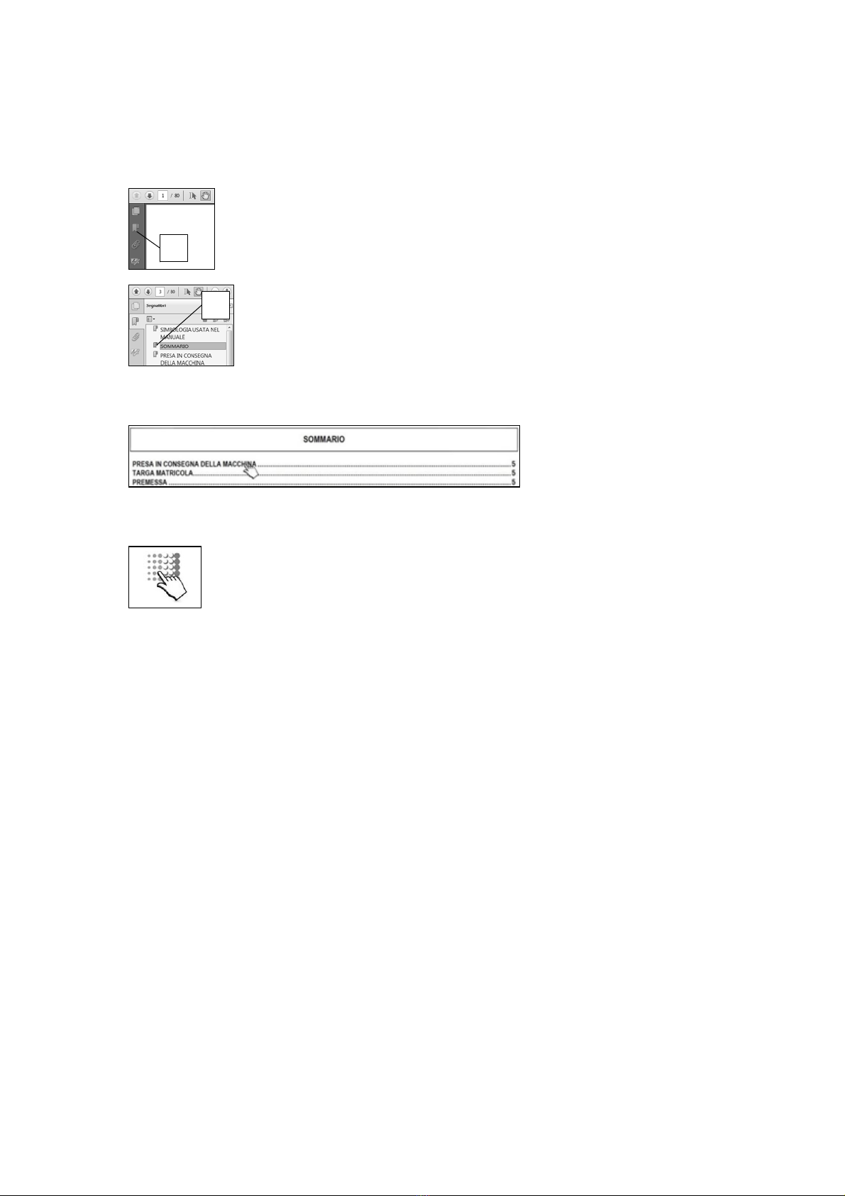
Fimap FSR B User manual

USE AND MAINTENANCE MANUAL
FSR B
FSR HYBRID
ED. 09-2013 EN
ORIGINAL
INSTRUCTIONS
Doc. 10043527
Ver. AA

The descriptions contained in this document are not binding.
The company therefore reserves the right to make any modifications at any time to
elements, details, or accessory supply, as considered necessary for reasons of
improvement or manufacturing/commercial requirements.
The reproduction, even partial, of the text and drawings contained in this document is
prohibited by law.
The company reserves the right to make any technical and/or supply modifications.
The images are for reference purposes only, and are not binding in terms of design
and supply.
SYMBOLS USED IN THE MANUAL
Open book symbol with an "i"
Indicates the need to consult the instruction manual
Open book symbol
Used to tell the operator to read the manual before using the
machine
Warning symbol
Carefully read the sections marked with this symbol and observe
the indications, for the safety of the operator and the machine
Warning symbol
Indicates danger of gas exhalation and leakage of corrosive
liquids
Warning symbol
Indicates the danger of fire.
Do not go near with free flames
Warning symbol
Indicates that the packed product should be handled with
suitable lifting means that comply with the legal requirements
Disposal symbol
Carefully read the sections marked with this symbol for machine
disposal

QUICK REFERENCE (ELECTRONIC DOCUMENT):
For quick reference of the electronic documents, use the Bookmarks and Links Pages:
Bookmarks:
Activate the "Bookmarks" panel of the interface browser, clicking the related icon (01), the icon may vary depending on the
version of the Acrobat viewer.
To view the desired paragraph, simply click on the title in the browser (02) that will take you to the desired destination.
Link Page:
To view the desired paragraph in the content of the document, simply click on the title of the paragraph that will take you to the
desired destination.
N.B.:
To return quickly to the contents of the document, simply click on the company logo at the top of this page, and it will sends
you back to the desired destination.
01
02

4
CONTENTS
ON CONSIGNMENT OF THE MACHINE............................................................................................................................................................6
INTRODUCTORY COMMENT............................................................................................................................................................................6
IDENTIFICATION DATA.....................................................................................................................................................................................6
TECHNICAL DESCRIPTION...............................................................................................................................................................................6
INTENDED USE..................................................................................................................................................................................................6
SERIAL NUMBER PLATE..................................................................................................................................................................................6
TECHNICAL DESCRIPTION...............................................................................................................................................................................7
SYMBOLS USED ON THE MACHINE................................................................................................................................................................8
GENERAL SAFETY REGULATIONS...............................................................................................................................................................10
MACHINE PREPARATION...............................................................................................................................................................................11
1. HANDLING OF THE PACKED MACHINE......................................................................................................................................................................... 11
2. HOW TO UNPACK THE MACHINE................................................................................................................................................................................... 11
3. HOW TO MOVE THE MACHINE....................................................................................................................................................................................... 11
4. HANDLEBAR CONTROL COMPONENTS........................................................................................................................................................................ 12
5. STEERING COLUMN COMPONENTS (B VERSIONS).................................................................................................................................................... 12
6. STEERING COLUMN COMPONENTS (HYBRID VERSIONS)......................................................................................................................................... 12
7. FOOTBOARD COMPONENTS.......................................................................................................................................................................................... 12
8. FRONT COMPONENTS.................................................................................................................................................................................................... 13
9. SIDE COMPONENTS........................................................................................................................................................................................................ 13
10. REAR COMPONENTS OF THE MACHINE..................................................................................................................................................................... 13
11. BATTERY TYPE (B VERSIONS)..................................................................................................................................................................................... 13
12. BATTERY TYPE (HYBRID VERSIONS).......................................................................................................................................................................... 14
13. BATTERY MAINTENANCE AND DISPOSAL.................................................................................................................................................................. 14
14. FITTING THE BATTERIES INTO THE MACHINE (B VERSIONS)................................................................................................................................. 14
15. FITTING THE BATTERIES INTO THE MACHINE (HYBRID VERSIONS)...................................................................................................................... 15
16. CONNECTING THE BATTERIES AND BATTERY CONNECTOR (B VERSIONS)........................................................................................................ 16
17. CONNECTING THE BATTERIES AND BATTERY CONNECTOR (HYBRID VERSIONS)............................................................................................. 17
18. BATTERY CHARGER CONNECTION (B VERSION, WITHOUT BC)............................................................................................................................. 17
19. BATTERY CHARGER CONNECTION (B VERSION, WITH BC).................................................................................................................................... 18
20. CONNECTING THE BATTERY CHARGER (HYBRID VERSIONS)................................................................................................................................ 20
21. BATTERY CHARGE LEVEL INDICATOR (B VERSIONS).............................................................................................................................................. 21
22. HOUR METER ................................................................................................................................................................................................................. 21
23. WORKING FORWARD SPEED....................................................................................................................................................................................... 21
24. BLINKING LIGHT (OPTIONAL)........................................................................................................................................................................................ 22
25. FILLING THE FUEL TANK (HYBRID VERSIONS).......................................................................................................................................................... 22
26. HEADLIGHTS................................................................................................................................................................................................................... 22
PREPARING TO WORK...................................................................................................................................................................................23
27. PREPARING TO WORK (B VERSIONS)......................................................................................................................................................................... 23
28. PREPARING TO WORK (HYBRID VERSIONS) ............................................................................................................................................................. 24
WORK ...............................................................................................................................................................................................................25
29. STARTING WORK (B VERSIONS).................................................................................................................................................................................. 25
30. STARTING WORK (HYBRID VERSIONS) ...................................................................................................................................................................... 27
31. EMERGENCY BUTTON................................................................................................................................................................................................... 31
32. ALTERNATOR FAULT WARNING LIGHT (HYBRID VERSIONS).................................................................................................................................. 31
33. EMPTYING THE DEBRIS HOPPER................................................................................................................................................................................ 32
AT THE END OF WORK...................................................................................................................................................................................34
DAILY MAINTENANCE ....................................................................................................................................................................................36
34. CLEANING THE CENTRAL BRUSH ............................................................................................................................................................................... 36
35. CLEANING THE SIDE BRUSH........................................................................................................................................................................................ 37
WEEKLY MAINTENANCE................................................................................................................................................................................38
36. CLEANING THE PANEL FILTER..................................................................................................................................................................................... 38
37. CLEANING THE FABRIC FILTER (OPTIONAL).............................................................................................................................................................. 39
38. CLEANING THE DEBRIS HOPPER................................................................................................................................................................................ 40
EMERGENCY MAINTENANCE........................................................................................................................................................................41

5
39. SIDE BRUSH ADJUSTMENT.......................................................................................................................................................................................... 41
40. CENTRAL BRUSH FLAP ADJUSTMENT........................................................................................................................................................................ 41
41. CENTRAL BRUSH REPLACEMENT............................................................................................................................................................................... 42
42. SIDE BRUSH REPLACEMENT........................................................................................................................................................................................ 43
MAINTENANCE OF THE COMBUSTION ENGINE..........................................................................................................................................44
TROUBLESHOOTING......................................................................................................................................................................................45
43. THE MACHINE DOES NOT START................................................................................................................................................................................ 45
44. THE ENDOTHERMIC ENGINE DOES NOT START....................................................................................................................................................... 45
45. THE MACHINE DOES NOT CLEAN WELL..................................................................................................................................................................... 45
46. THE MACHINE LIFTS DUST DURING OPERATION...................................................................................................................................................... 45
47. EXCESSIVE OR ALTERED NOISE OF THE CENTRAL BRUSH................................................................................................................................... 45
48. EXCESSIVE OR ALTERED NOISE OF THE SIDE BRUSH ........................................................................................................................................... 45
DISPOSAL ........................................................................................................................................................................................................46
CHOOSING AND USING THE BRUSHES.......................................................................................................................................................47
EC DECLARATION OF CONFORMITY............................................................................................................................................................48

6
ON CONSIGNMENT OF THE MACHINE
When the machine is consigned to the customer, an immediate check
must be performed to ensure all the material mentioned in the shipping
documents has been received, and also to check the machine has not
suffered damage during transportation. If this is the case, the carrier
must ascertain the extent of the damage at once, informing our
customer service office. It is only by prompt action of this type that the
missing material can be obtained, and compensation for damage
successfully claimed.
INTRODUCTORY COMMENT
Even the best machines will only work well if used correctly and kept in
good working order. We therefore suggest you read this instruction
booklet carefully and read it again whenever difficulties arise while using
the machine. If necessary, remember that our assistance service
(organised in collaboration with our dealers) is always available for
advice or direct intervention.
IDENTIFICATION DATA
For technical assistance or to request replacement parts, always give
the model, the version and serial number written on the serial number
plate.
TECHNICAL DESCRIPTION
The FSR are ride-on sweeping machines, powered electrically (with
traction batteries) or with an internal combustion (endothermic) engine,
for the cleaning of both internal and external surfaces with tiled, concrete
or asphalt floors.
The machine must operate on dry surfaces, and if necessary can also
work on wet surfaces making sure the vacuum action is not active. The
machine features a central brush for the collection of brushed up
material, a side brush for cleaning edges and corners, a vacuum system
with filter to avoid raising dust, and a debris hopper that can be manually
removed by means of a mechanical leverage.
INTENDED USE
The sweeping machine is designed to clean both inside and outside
surfaces with tiled, concrete and asphalt floors, for professional use in
industrial, commercial and public places. The machine is only suitable
for use in closed (or at least covered) places. The machine is not
suitable for use in the rain, or under water jets. It is FORBIDDEN to use
the machine for picking up dangerous dusts or inflammable liquids within
places with a potentially explosive atmosphere. In addition, it is not
suitable as a means of transport for people or objects.
SERIAL NUMBER PLATE
The serial number plate is located at the rear of the steering column,
and indicates the general characteristics of the machine, in particular the
serial number of the machine.The serial number is an extremely
important piece of information and should always be provided together
with any request for assistance or to purchase spare parts.

7
TECHNICAL DESCRIPTION UM FSR B FSR HYBRID
Working width without side brush mm 580 580
Working width with right side brush mm 790 790
Working width with left and right side brush mm 1000 1000
Working capacity, up to (2SL version with two side brushes) m2/h 5100 4600
Central brush Ø mm 260 260
Side brush Ø mm 400 400
Central brush rpm
rpm. 550 550
Side brush rpm rpm 65 65
Endothermic engine HP / rpm - 4.8 / 3600
Central brush motor V/W 24/380 24/380
Side brush motor V/W 24/90 24/90
Traction motor V/W 24/300 24/300
Vacuum motor V/W 24/400 24/400
Filter shaker motor V/W 24/80 24/80
Total power W 1250 1250
Front wheel ((number / (diameter x width)) No. / (mm x mm) 1 / (175x60) 1 / (175x60)
Rear wheel ((number / (diameter x width)) No. / (mm x mm) 1 / (225x69) 1 / (230x88)
Working forward speed km/h 4.8 4.8
Maximum gradient % 10 10
Filter surface area (optional fabric filter) m22.2 2.2
Filter surface area (paper filter) m23.2 3.2
Debris hopper volume dm320 20
Steering diameter mm 3600 3600
Machine length mm 1455 1455
Machine height mm 1030 1030
Machine height with blinking light mm 1080 1080
Machine width mm 845 845
Battery compartment (l x w x h) mm 340x174x310 -
Battery compartment (l x w x h) mm - 270x360x240
Rated battery voltage V 12 12
Battery weight kg 36.5 20
Unladen machine weight (without batteries) kg 175 -
Unladen machine weight (Combustion engine without fuel) kg - 252
Machine weight during transport (machine + batteries + brushes) kg 248 -
Machine weight during transport (machine + brushes + Combustion
engine without fuel) kg - 255
Machine weight in running order (machine + batteries + brushes +
operator) kg 323 -
Machine weight in running order (machine + brushes + Combustion
engine fuel + operator) kg - 325
Sound pressure level (ISO 11201) - L pA dB (A) 60.5 81.2
Uncertainty KpA dB (A) 1.4 1.4
Hand vibration level (ISO 5349) m/s2<2.5 <2.5
Body vibration level (ISO 2631) m/s2<0.5 <0.5

8
SYMBOLS USED ON THE MACHINE
Main switch symbol (version B)
Used on the steering column to indicate the key switch for machine operation on (I) or off (0)
Main switch symbol (Hybrid version )
Used on the steering column to indicate the key switch that manages the type of power supply of the machine.
Alternator fault symbol (Hybrid version).
Used on the steering column to indicate with red warning light of a fault in the electrical system inherent to the alternator.
Horn symbol
Used to indicate the acoustic alarm button.
Symbol of the reverse movement selector.
Used to indicate the button for engaging the reverse gear.
Filter shaker symbol.
Used on the instrument panel to indicate the button that starts the vibrating shaker on the filter unit.
Symbol denoting vacuum motor.
Used on the instrument panel to indicate the button that commands the deactivation of the vacuum motor.
Central brush movement symbol (idle position)
Used on the rear of the steering column to indicate the movement lever of the central brush.
Central brush movement symbol (working position)
Used on the rear of the steering column to indicate the movement lever of the central brush.

9
SYMBOLS USED ON THE MACHINE
Side brush/es movement symbol (idle position)
Used on the rear of the steering column to indicate the movement lever of the side brush/es.
Side brush/es movement symbol (working position)
Used on the rear of the steering column to indicate the movement lever of the side brush/es.
Combustion engine pull start symbol.
Used to indicate the position of the handle that allows the pull start of the combustion engine.
Danger of contact with live parts symbol (Hybrid version).
Used on the cover of the electrical system's control board.
Indicates the risk of crushed hands
Indicates the risk of burns due to the hot surface
Indicates the maximum gradient
Open book symbol
Used to tell the operator to read the manual before using the machine.

10
GENERAL SAFETY REGULATIONS
The regulations below must be carefully followed in order to avoid harm to the operator and damage to the machine.
WARNING:
Read the labels on the machine carefully. Do not cover them for any reason and replace them immediately if they become damaged.
The machine must be used exclusively by authorised and trained personnel.
The machine is designed for dry use only.
Do not use the machine on surfaces with an inclination greater than the one shown on the plate.
The machine is not suitable for cleaning rough or uneven floors. Do not use the machine on slopes.
In the event of danger, quickly intervene on the emergency button or the handle located on the battery connector.
Before carrying out any maintenance work, switch off the machine and disconnect the battery connector.
Children must be supervised to ensure they do not play with the device.
During the working of the machine, pay attention to other people and especially to children.
Only use the brushes supplied with the machine, or those specified in the "CHOOSING AND USING THE BRUSHES" paragraph of the instruction
manual. The use of other brushes could compromise safety levels.
WARNING:
The machine is not suitable for use by children and persons with reduced physical, mental and sensory capabilities, or people who lack experience and
knowledge.
The machine must not be used or stored outdoors, in damp conditions or directly exposed to rain.
The storage temperature must be between -25C and +55C; do not store outdoors in damp conditions.
Conditions of use: room temperature between 0°C and 40°C with relative humidity between 30 and 95%.
The socket for the battery charger cable must have a prescribed earth connection.
Adapt the speed to the adhesion conditions.
Do not use the machine as a means of transport.
The machine does not cause harmful vibrations.
Do not use the machine in an explosive atmosphere.
Do not use the device to collect dangerous powders.
The machine is not suitable for cleaning carpets.
Do not place any liquid containers on the machine.
Avoid working with the brushes when the machine is standing still, so as not to damage the floor.
In the event of a fire, use a powder extinguisher. Do not use water.
Do not knock against shelving or scaffolding, where there is a danger of falling objects. The operator must always be equipped with the appropriate
safety devices (gloves, shoes, helmet, goggles, etc.).
If the machine does not work properly, check this is not caused by failure to carry out routine maintenance. Otherwise, ask for intervention of the
authorised technicalassistancecentre.
If you need to replace any components, request the ORIGINAL spare parts from an Authorised dealer and/or Retailer.
Restore all electrical connections after any maintenance interventions.
Before using the machine, check that all the hatches and covers are positioned as shown in this Use and Maintenance Manual.
Do not remove any protection devices which require the use of tools in order to be removed.
Do not wash the machine with direct water jets or with pressurised water, nor with corrosive substances.
Have the machine checked by an authorised technical assistance centre every year.
When disposing of consumable materials, observe the laws and regulations in force.
When your machine has reached the end of its long working life, dispose of the materials it contains (especially oils, batteries and electronic
components) in an appropriate manner, taking into account that the machine itself was constructed using 100% recyclable materials.
The batteries must be removed from the machine before its disposal. The batteries must be disposed of in a safe manner, fully observing the laws and
regulations in force.
Keep children and animals away from the powered motor, as itheats upand maycause burns andinjuries (both directly andvia themachineswhichit moves).
Learn how to switch the motor off quickly, and how to use all the controls. Never entrust the motor to people who haven't had the appropriate training.
While the motor is switched on, do not place any inflammable objects (gasoline, matches, etc.) near it.
Top up the fuel in a well-ventilated area, with the motor switched off. gasoline is highly inflammable and may explode.
Do not completely fill the fuel tank. Check the cap is firmly closed.
If any fuel is spilt, clean the area thoroughly and allow the vapours to disperse before switching on the motor.
Do not smoke or take any unprotected flames in the area where the motor is filled with fuel, or where the gasoline is stored.
The exhaust gases contain carbon monoxide - an odourless, colourless, but highly poisonous gas. Avoid inhalation. Do not switch the motor on in a
closed garage or in a room without windows.

11
MACHINE PREPARATION
1. HANDLING OF THE PACKED MACHINE
The machine is contained in specific packaging with a pallet for the handling with fork trucks. The
packages cannot be placed on top of each other.
The total weight of the machine with its packaging is 210 kg (for FSR B versions)
The total weight of the machine with its packaging is 290 kg (for FSR HYBRID versions)
The dimensions of the packaging are as follows:
FSR
A : 1270 mm
B : 1020 mm
C : 1760 mm
A
CB
2. HOW TO UNPACK THE MACHINE
1. Remove the outer package.
2. Disengage the electronic brake, turn the lever (1) (on the rear right-hand side of the machine) clockwise.
3. The machine is fixed to the pallet with wedges which block the wheels.Remove the wedges.
4. Use a chute to get the machine down from the pallet, pushing it backwards.
ATTENTION: During transportation, the electrical brake should not be engaged, the
machine will in any event, if the critical speed threshold is crossed, activate the
internal braking system of the chopper circuit board and will emit a warning noise.
5. Keep the pallet for any future transport needs
WARNING: If the product is delivered in cardboard containers, handle the packed
product with suitable lifting means that comply with the legal requirements
WARNING: During this operation, check there are no people or objects near the
machine
3. HOW TO MOVE THE MACHINE
1. Check that the central brush is lifted from the ground, otherwise lift it by moving the lever on the rear
of the steering column.
2. Check that the side brush/es is/are lifted from the ground, otherwise lift it/them by moving the lever
on the rear of the steering column.
3. Place it on a pallet using a chute.
4. Check the main switch is in the “0” position, if this is not the case, turn the key by a quarter of a turn
to the left.
5. Remove the key from the main switch.
6. Secure the machine to the pallet using wooden wedges.
7. Engage the electronic brake.

12
MACHINE PREPARATION
WARNING:Withregardto the transport of a hybridversionmachine, follow the instructions
given in the usermanualofthecombustion engine (suppliedwiththemachine).
4. HANDLEBAR CONTROL COMPONENTS
The handlebar control components are identified as follows:
1. Level indicator for battery/hour meter.
2. Filter shaker control button.
3. Horn button.
4. Reverse button.
5. Vacuum motor "STOP" button.
5. STEERING COLUMN COMPONENTS (B VERSIONS)
The steering column components are identified as follows:
1. Central brush lifting lever.
2. Lever for raising the side brush (1SL version) or brushes (2SL version).
3. Main key switch.
4. Emergency button.
6. STEERING COLUMN COMPONENTS (HYBRID VERSIONS)
The steering column components are identified as follows:
1. Central brush lifting lever.
2. Lever for raising the side brush (1SL version) or brushes (2SL version).
3. Main key switch.
4. Emergency button.
5. Red warning light, which warns of a malfunction of the alternator to the electrical system.
7. FOOTBOARD COMPONENTS
The footboard components are identified as follows:
1. Drive pedal, accelerator pedal
2. Front flap lifting pedal

13
MACHINE PREPARATION
8. FRONT COMPONENTS
The front components of the machine are identified as follows:
1. Storage compartment.
2. Headlights.
9. SIDE COMPONENTS
The components on the side of the machine are identified as follows:
1. Left side panel central brush engage/adjustment.
2. Seat unit lifting handle.
3. Right side panel central brush maintenance.
4. Seat unit lifting handle.
10. REAR COMPONENTS OF THE MACHINE
The rear components of the machine are identified as follows:
1. Debris hopper retainer.
2. Debris hopper handle.
3. Blinking light (optional).
11. BATTERY TYPE (B VERSIONS)
Power to the machine must be supplied by sealed traction batteries with gas recombination or gel
technology. OTHER TYPES MUST NOT BE USED.
The batteries must meet the requirements laid out in the norms: CEI EN 60254-1:2005-12 (CEI 21-5) +
CEI EN 60254-2:2008-06 (CEI 21-7)
The battery compartment can house two 12V batteries
For a good operating performance, we suggest the use of 105 Ah C5 batteries

14
MACHINE PREPARATION
12. BATTERY TYPE (HYBRID VERSIONS)
To power the machine, "double application" sealed batteries must be used, starter and total discharge
OPTIMA BT DC 4.2 12V 55Ah. OTHER TYPES MUST NOT BE USED.
The batteries must meet the requirements laid out in the norms: CEI EN 60254-1:2005-12 (CEI 21-5) +
CEI EN 60254-2:2008-06 (CEI 21-7)
The battery compartment can house two 12V - 55 Ah batteries
13. BATTERY MAINTENANCE AND DISPOSAL
For information about battery maintenance, refer to the instructions provided by the battery manufacturer.
When the battery reaches the end of its working life, it must be disconnected by expert, trained personnel,
then lifted (using the grips and suitable lifting devices) to remove it from the battery compartment.
EXHAUSTED BATTERIES ARE CLASSIFIED AS DANGEROUS WASTE AND MUST BE CONSIGNED
TO THE AUTHORISED BODIES FOR CORRECT DISPOSAL.
WARNING: you are advised to always wear protective gloves, to avoid the risk
of serious injury to your hands.
WARNING: You are advised to only lift and move the batteries with lifting and
transportation means suitable for the specific weight and size
14. FITTING THE BATTERIES INTO THE MACHINE (B VERSIONS)
The batteries must be housed in the appropriate compartment beneath the seat unit. They should be
handled using lifting equipment that is suitable in terms of both weight and coupling system. They must
also satisfy the requirements of Standard CEI 21-5. The dimensions of the battery compartment are:
340 x 174 x H310 mm.
WARNING: For battery maintenance and daily recharging, you must carefully follow
the instructions provided by the manufacturer or retailer. All installation and
maintenance operations must be carried out by specialised personnel.
WARNING: Ensure that you comply with the accident prevention regulations in force in
the country where you work or with DIN EN 50272-3 and DIN EN 50110-1, before any
handling of the batteries.
WARNING: To prevent an accidental short circuit use insulated tools to connect the
batteries, and do not place or drop metal objects on the battery. Remove rings,
watches and any clothing with metal parts that may come into contact with the battery
terminals.
To insert the batteries into the compartment proceed as follows:
1. Make sure the electric brake is engaged, otherwise engage it using the lever (1) located at the left
rear of the machine (working direction).
2. Check the main switch (2) is in the “0” position, if this is not the case, turn the key by a quarter of a
turn to the left, and remove the key from the instrument panel.

15
MACHINE PREPARATION
3. Grasp the handle located on the side of the operator seat unit.
4. Lift the operator seat unit until the safety clamp (3) is hooked.
WARNING: Before installing the battery, clean the battery compartment with a damp
cloth. Check that the connectors on the cables supplied are functioning correctly.
WARNING: Check that the characteristics of the battery that you are looking to use are
appropriate for the type of work to be performed. Check the battery charge and the
condition of the contacts on the battery.
WARNING: You are advised to only lift and move the batteries with lifting and
transportation means suitable for the specific weight and size.
WARNING: The lifting hooks must not damage the blocks, connectors or cables.
5. House the batteries in the compartment, positioning the poles “+” and “-“ opposite each other.
WARNING: Before inserting the batteries into the machine, remember to cover the
terminals with a little grease to protect them against external corrosion.
WARNING: You are advised to use airtight batteries only, to avoid the leakage of acids!
WARNING: You are advised to always wear protective gloves, to avoid the risk of
serious injury to your hands.
15. FITTING THE BATTERIES INTO THE MACHINE (HYBRID VERSIONS)
The batteries must be housed in the appropriate compartment beneath the seat unit. They should be
handled using lifting equipment that is suitable in terms of both weight and coupling system. They must
also satisfy the requirements of Standard CEI 21-5. The dimensions of the battery compartment are:
270 x 360 x H240 mm.
WARNING: For battery maintenance and daily recharging, you must carefully follow the
instructions provided by the manufacturer or retailer. All installation and maintenance
operations must be carried out by specialised personnel.
WARNING: Ensure that you comply with the accident prevention regulations in force in
the country where you work or with DIN EN 50272-3 and DIN EN 50110-1, before any
handling of the batteries.
WARNING: To prevent an accidental short circuit use insulated tools to connect the
batteries, and do not place or drop metal objects on the battery. Remove rings, watches
and any clothing with metal parts that may come into contact with the battery terminals.
To insert the batteries into the compartment proceed as follows:
1. Make sure the electric brake is engaged, otherwise engage it using the lever (1) located at the left
rear of the machine (working direction).
2. Check the main switch (2) is in the “0” position, if this is not the case, turn the key by a quarter of a
turn to the left, and remove the key from the instrument panel.

16
MACHINE PREPARATION
3. Grasp the handle located on the side of the operator seat unit.
4. Lift the operator seat unit until the safety clamp (3) is hooked.
5. Check that the motor switch is in the “0” position, if this is not the case, turn the handle by a quarter
of a turn to the left, and remove the key from the instrument panel.
6. Using the appropriate tools, remove the screws (4) securing the grille (5) on the leftside to the body.
7. Remove the grille (5) on the left side of the body.
WARNING: Before installing the battery, clean the battery compartment with a damp
cloth. Check that the connectors on the cables supplied are functioning correctly.
WARNING: Check that the characteristics of the battery that you are looking to use are
appropriate for the type of work to be performed. Check the battery charge and the
condition of the contacts on the battery.
8. Using the appropriate tools, remove the screws (6) securing the plate (7) of the control board support.
9. Remove the control board unit.
WARNING: You are advised to only lift and move the batteries with lifting and
transportation means suitable for the specific weight and size.
WARNING: The lifting hooks must not damage the blocks, connectors or cables.
10. House the batteries in the compartment, positioning the poles “+” and “-“ opposite each other.
11. Secure the batteries among them by means of the belt (8) supplied.
16. CONNECTING THE BATTERIES AND BATTERY CONNECTOR (B VERSIONS)
To connect the batteries proceed as follows:
1. Connect the batteries in series to the "+" and "-" poles using the supplied jumper cable (1).
2. Connect the battery connector cable to the "+" and "-" poles in order to obtain the terminal voltage
of 24V.
3. Connect the electric system connector (3) to the battery connector (2).
WARNING: All installation and maintenance operations must be carried out by expert
personnel, trained at the specialised assistance centre.
WARNING: you are advised to always wear protective gloves, to avoid the risk of
serious injury to your hands.
2
1
3

17
MACHINE PREPARATION
17. CONNECTING THE BATTERIES AND BATTERY CONNECTOR (HYBRID VERSIONS)
To connect the batteries proceed as follows:
1. Using the appropriate tools, remove the screws (1) securing the plate (2) of the control board
support.
2. Remove the control board unit.
3. Connect the batteries in series to the "+" and "-" poles using the supplied jumper cable (3).
4. Connect the battery connector cable (4) to the “+” and “-“ poles to obtain a voltage of 24V on the
terminals.
5. Connect the electrical system connector to the battery connector.
18. BATTERY CHARGER CONNECTION (B VERSION, WITHOUT BC)
In order not to cause permanent damage to the batteries, it is essential to avoid their complete discharge:
arrange the recharge within a few minutes of the switching on of the "discharged batteries" blinking light.
WARNING: Never leave the batteries completely discharged, even if the machine is not
being used. Check the battery charger is suitable for the batteries installed, in terms of
both capacity and type.
To connect the battery charger you must:
1. Move the machine to the place used for maintenance or recharging the batteries.
2. Make sure the electric brake is engaged, otherwise engage it using the lever (1) located at the left
rear of the machine (working direction).
3. Check the main switch (2) is in the “0” position, if this is not the case, turn the key by a quarter of a
turn to the left, and remove the key from the instrument panel.
4. Grasp the handle located on the side of the operator seat unit.
5. Lift the operator seat unit until the safety clamp (3) is hooked.
WARNING: Park the machine in an place protected from the weather and with suitable
ventilation, and on a flat and level surface; near the machine there must be no objects
that could either damage it, or be damaged through contact with it.
6. Disconnect the electric system connector (4) from the battery connector (5).
ATTENTION: this process must be carried out by qualified personnel. An incorrect
connection of the connector may cause problems with machine functioning.
3
4

18
MACHINE PREPARATION
7. Connect the battery charger cable (6) to the battery connector (5).
WARNING: Keep the seat unit open for the duration of the battery recharging cycle to
allow gas fumes to escape.
WARNING: The room used to recharge the batteries must be adequately ventilated to
prevent the accumulation of gases that leak from batteries.
The coupling connector of the battery charger is supplied inside the bag containing this instruction
booklet, and must be fitted to the battery charger cables as shown in the instructions.
8. Connect the recently wired cable to the external battery charger.
WARNING: Carefully read the use and maintenance instructions of the battery charger
that is used for charging.
WARNING: Danger of gas exhalation and leakage of corrosive liquids.
WARNING: Danger of fire: do not go near with free flames
9. When the recharge cycle is complete, disconnect the battery charger connector from the external
battery charger.
10. Disconnect the battery charger cable (6) from the battery connector (5).
11. Connect the battery connector (5) to the electric system connector (4).
12. Grasp of the handle located on the side of the operator seat unit and lower the seat unit until it is in
the working position.
19. BATTERY CHARGER CONNECTION (B VERSION, WITH BC)
In order not to cause permanent damage to the batteries, it is essential to avoid their complete discharge:
arrange the recharge within a few minutes of the switching on of the "discharged batteries" blinking light.
WARNING: Never leave the batteries completely discharged, even if the machine is
not being used. Check the battery charger is suitable for the batteries installed, in
terms of both capacity and type.

19
MACHINE PREPARATION
To connect the battery charger you must:
1. Move the machine to the place used for maintenance or recharging the batteries.
2. Make sure the electric brake is engaged, otherwise engage it using the lever (1) located at the left
rear of the machine (working direction).
3. Check the main switch (2) is in the “0” position, if this is not the case, turn the key by a quarter of a
turn to the left, and remove the key from the instrument panel.
4. Grasp the handle located on the side of the operator seat unit.
5. Lift the operator seat unit until the safety clamp (3) is hooked.
WARNING: Park the machine in an place protected from the weather and with suitable
ventilation, and on a flat and level surface; near the machine there must be no objects
that could either damage it, or be damaged through contact with it.
6. Remove the battery charger cover (4).
7. Connect the battery charger power cable connector to the socket on the charger itself.Before
inserting the power cable into the socket of the charger, verify that there is no condensate or other
forms of liquids.
8. Plug the battery charger power cable into the mains socket.
WARNING: Carefully read the use and maintenance manual of the charger that is
delivered inside the bag containing this instruction booklet.
WARNING: Keep the seat unit open for the duration of the battery recharging cycle to
allow gas fumes to escape.
WARNING: The room used to recharge the batteries must be adequately ventilated to
prevent the accumulation of gases that leak from batteries.
9. When the recharge cycle is complete, disconnect the battery charger cable from the mains.
10. Disconnect the battery charger power cable connector from the socket on the charger itself.
11. Replace the battery charger cover (4).
12. Grasp of the handle located on the side of the operator seat unit and lower the seat unit until it is in
the working position.
WARNING: if the machine's electric system is accidentally powered (by turning the
main switch to "I"), the commands display will show “BATTERY-CHARGER” and no
steering wheel command will function.
WARNING: Always make sure the green LED of the battery charger is on before using
the machine again.
4
4

20
MACHINE PREPARATION
20. CONNECTING THE BATTERY CHARGER (HYBRID VERSIONS)
In order not to cause permanent damage to the batteries, it is essential they are fully charged using a
suitable battery charger, after the non-use of the machine for a long period or after ten complete discharge
cycles of the batteries.
WARNING: Never leave the batteries completely discharged, even if the machine is
not being used. Check the battery charger is suitable for the batteries installed, in
terms of both capacity and type.
To connect the battery charger you must:
1. Move the machine near to the battery charger.
2. Make sure the electric brake is engaged, otherwise engage it using the lever (1) located at the left
rear of the machine (working direction).
3. Check the main switch (2) is in the “0” position, if this is not the case, turn the key by a quarter of a
turn to the left, and remove the key from the instrument panel.
4. Grasp the handle located on the side of the operator seat unit.
5. Lift the operator seat unit until the safety clamp (3) is hooked.
WARNING: Park the machine in an place protected from the weather and with suitable
ventilation, and on a flat and level surface; near the machine there must be no objects
that could either damage it, or be damaged through contact with it.
6. Check that the motor switch is in the “0” position, if this is not the case, turn the handle by a quarter
of a turn to the left, and remove the key from the instrument panel.
7. Disconnect the electric system connector (4) from the battery connector (5)
ATTENTION: this process must be carried out by qualified personnel. An incorrect
connection of the connector may cause problems with machine functioning.
8. Connect the battery charger cable (6) to the battery connector (5).
WARNING: Keep the seat unit open for the duration of the battery recharging cycle to
allow gas fumes to escape.
WARNING: The room used to recharge the batteries must be adequately ventilated to
prevent the accumulation of gases that leak from batteries.
The coupling connector of the battery charger is supplied inside the bag containing this instruction
booklet, and must be fitted to the battery charger cables as shown in the instructions.
9. Connect the recently wired cable to the external battery charger.
WARNING: Carefully read the use and maintenance instructions of the battery charger
that is used for charging.
This manual suits for next models
1
Table of contents
Other Fimap Floor Machine manuals

Fimap
Fimap 1500 S-V User manual

Fimap
Fimap FM43 F User manual

Fimap
Fimap Mx Series User manual

Fimap
Fimap MR60 B User manual

Fimap
Fimap BMg Sanitizer User manual

Fimap
Fimap FM43 ORB User manual

Fimap
Fimap MXR Instruction manual

Fimap
Fimap Minny 420 Installation instructions

Fimap
Fimap IMx Instruction manual

Fimap
Fimap FS80 B User manual