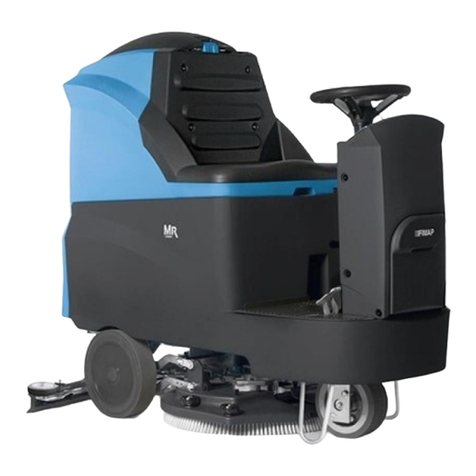
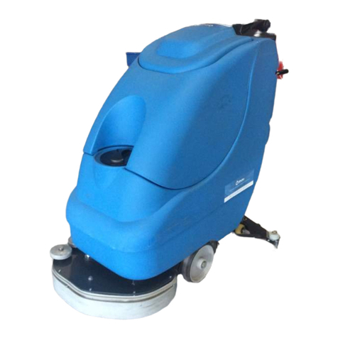
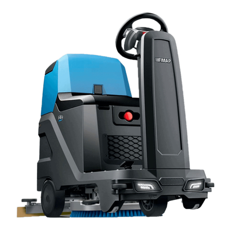
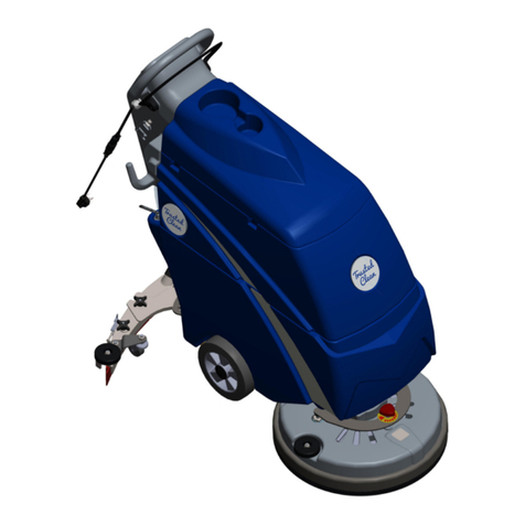
Fimap GAMMA 66 User manual

USE AND MAINTENANCE MANUAL
GAMMA 66 – 83II
ED. 02-2010 EN
ORIGINAL
INSTRUCTIONS
Doc. 10022323
Ver. AB

The contained descriptions in the present publication are not binding. The company
therefore reserves itself the right to bring in whatever moment possible organs changes,
details or supplies of accessories, that it holds convenient for an improvement, or for any
demand of constructive or commercial character.
The partial reproduction of the texts and diagrammes contained in the present catalog, is
forbidden by law.
The company reserves itself the right to bring changes of technical character and/or of
endowment. The images are meant of pure reference and not binding in terms of design
and endowment.
Symbols used in the manual
Symbol of the book open with letter i
It points out that this document is a manual of instructions.
Symbol of the open book
It points out to the operator to read the manual of use before using
the machine.
Symbol of warning
Read attentively the sections preceded by this symbol for the safety
of the operator and the machine

3
CONTENTS
ON CONSIGNMENT OF THE MACHINE ..........................................................................................................................................4
INTRODUCTORY COMMENT.........................................................................................................................................................4
TECHNICAL FEATURES................................................................................................................................................................5
SYMBOLS USED ON THE MACHINE..............................................................................................................................................6
SYMBOLS USED ON THE MANUAL...............................................................................................................................................8
GENERAL SAFETY REGULATIONS ................................................................................................................................................9
MACHINE PREPARATION ...........................................................................................................................................................10
1. MOVING THE PACKAGED MACHINE ........................................................................................................................................................ 10
2. HOW TO UNPACK THE MACHINE ............................................................................................................................................................ 10
3. CONNECTING THE DRIVE MOTOR CABLE................................................................................................................................................ 10
4. PUTTING THE BATTERIES IN THE MACHINE ............................................................................................................................................ 11
5. CONNECTING THE BATTERY CONNECTOR .............................................................................................................................................. 11
6. CONNECTING THE BATTERY CHARGER................................................................................................................................................... 11
7. BATTERY RECHARGING.......................................................................................................................................................................... 12
8. BATTERY CHARGE LEVEL GAUGE ........................................................................................................................................................... 12
9. ASSEMBLING THE SQUEEGEE................................................................................................................................................................. 13
10. ADJUSTING THE SQUEEGEE.................................................................................................................................................................... 13
11. INSTALLING THE ROTATING BRUSHES ................................................................................................................................................... 14
12. RECOVERY TANK.................................................................................................................................................................................... 15
13. SOLUTION TANK..................................................................................................................................................................................... 15
WORK .......................................................................................................................................................................................16
OVERFLOW DEVICE ........................................................................................................................................................................................ 17
BRUSH PRESSURE ......................................................................................................................................................................................... 17
TRACTION ...................................................................................................................................................................................................... 17
TRACTION ...................................................................................................................................................................................................... 18
BRAKES.......................................................................................................................................................................................................... 18
UPON COMPLETION OF WORK...................................................................................................................................................19
DAILY MAINTENANCE................................................................................................................................................................20
CLEANING THE RECOVERY TANK.................................................................................................................................................................... 20
CLEANING THE RECOVERY TANK FILTER ........................................................................................................................................................ 20
CLEANING THE SOLUTION TANK FILTERS ....................................................................................................................................................... 21
CLEANING THE SQUEEGEE.............................................................................................................................................................................. 22
REPLACING THE REAR SQUEEGEE RUBBER.................................................................................................................................................... 22
REMOVING THE ROTATING BRUSHES............................................................................................................................................................. 22
TROUBLE SHOOTING GUIDE ......................................................................................................................................................23
INSUFFICIENT WATER TO THE BRUSHES ........................................................................................................................................................ 23
MACHINE DOES NOT CLEAN WELL ................................................................................................................................................................. 23
SQUEEGEE DOES NOT DRY PERFECTLY.......................................................................................................................................................... 23
ASPIRATION UNIT DOES NOT OPERATE .......................................................................................................................................................... 24
TOO MUCH FOAM IS GENERATED ................................................................................................................................................................... 24
CHOICE AND USE OF BRUSHES .................................................................................................................................................25
EC DECLARATION OF CONFORMITY...........................................................................................................................................26

4
On consignment of the machine
When the machine is consigned to the customer, an immediate
check must be performed to ensure all the material mentioned in
the shipping documents has been received, and also to check the
machine has not suffered damage during transportation. If this is
the case, the carrier must ascertain the extent of the damage at
once, informing our customer service office. It is only by prompt
action of this type that the missing material can be obtained, and
compensation for damage successfully claimed.
Introductory comment
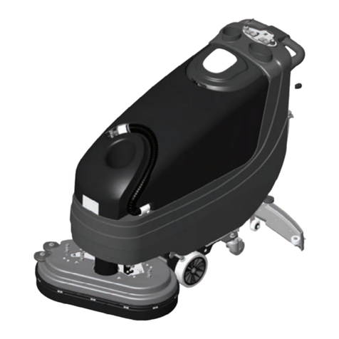
This is a floor scrubber-dryer which, via the mechanical action of
the rotating brush and the chemical action of a water/detergent
solution, can clean any type of flooring. As it advances, it also
collects the dirt removed and the detergent solution not absorbed
by the floor.
The machine must be used only for this purpose. Even the best
machines will only work well if used correctly and kept in good
working order. We therefore suggest you read this instruction
booklet carefully and re-read it whenever difficulties arise while
using the machine. If necessary, remember that our assistance
service (organised in collaboration with our dealers) is always
available for advice or direct intervention.

5
Technical features U/M Gamma 66 Gamma 83II
Working width mm 660 830
Width of squeegee mm 976 1075
Work capacity till m2/h 2100 2700
Water consumption g/m2 91 91
Brushes ∅mm (2) 345 (2) 430
Brush rotations rpm 200 180
Max brush pressure kg 80 80
Max specific pressure g/cm266 37
Brush motor tension V 36 36
Brush motor power W 900 1125
Drive motor tension V 36 36
Drive motor power W 300 300
Type of drive aut. aut.
Forward and riverse speed km/h 0÷4 0÷4
Max gradient 10% 10%
Suction motor tension V 36 36
Suction motor power W 670 670
Suction vacuum mbar 190 190
Solution tank capacity l 90 90
Recovery tank capacity l 120 120
Machine length mm 1600 1630
Machine height mm 1100 1100
Machine width
Sb i
mm 680 850
Battery compartment dimensions mm 380x840xH365
Batteries V/Ah 36/260 36/260
Battery weight kg 315 315
Total machine weight (excluding batteries) kg 185 210
Noise level (in compliance with IEC 704/1) dB (A) 70 70
Harmful Vibration level m/s20,71 0,70

6
SYMBOLS USED ON THE MACHINE
OFF/0 ON/ 1
Indicates the general switch
Cock symbol
Indicates the cock open signal lamp
Brush base lift/lower symbol
Indicates the base lift lever
Squeegee lift/lower symbol
Indicates the Squeegee lever
Brush symbol
Indicates the brush motor switch
Aspiration motor symbol
Indicates the aspiration motor switch
Battery charge level symbol

7
SYMBOLS USED ON THE MACHINE
Brake symbol
Indicates the hand brake engaged signal lamp
Used over the emergency brake lever
Brake symbol
Indicates the parking brake disengaged position
Indicates the maximum temperature of the detergent solution
Located near the solution tank inlet
Open book symbol
Used to tell the operator to read the manual before using the machine

8
SYMBOLS USED ON THE MANUAL
Warning symbol
Carefully read the sections preceded by this symbol, for operator and machine safety
Indicates danger of gas fumes and spillage of corrosive liquids
Indicates fire danger
Do not approach with open flames

9
GENERAL SAFETY REGULATIONS
The regulations below must be carefully followed in order to avoid harm to the operator and damage to the machine
•Read the labels on the machine carefully. Do not cover them for any reason and replace them immediately if they become damaged
•The machine must be used exclusively by authorised, trained personnel
•During the working of the machine, pay attention to other people and especially to children
•Do not mix different types of detergent as this may produce noxious gases
•Do not place any liquid containers on the machine
•The storage temperature must be between -25C and +55C; do not store outdoors in damp conditions
•Conditions of use: room temperature between 0C and 40C with relative humidity between 30 and 95%
•Do not use the machine in an explosive atmosphere
•Do not use the machine as a means of transport
•Do not use acid solutions, which may damage the machine or people
•Avoid working with the brushes when the machine is standing still, so as not to damage the floor
•Do not vacuum inflammable liquids
•Do not use the device to collect dangerous powders
•In the event of a fire, use a powder extinguisher. Do not use water
•Do not knock against shelving or scaffolding, where there is a danger of falling objects
•Adjust the speed of using the grip conditions
•Do not use the machine on surfaces with an inclination greater than the one shown on the plate
•When the car is parked, get off the key and engage parking brake
•The machine is designed to carry out the washing and drying operations simultaneously. Different operations should only be carried
out in areas where the passage of unauthorised persons is prohibited. Signal the presence of damp floors with suitable signs
•If the machine does not work properly, check this is not caused by failure to carry out routine maintenance. Otherwise, request the
intervention of the FIMAP technical assistance centre
•If you need to replace any components, request the ORIGINAL spare parts from a FIMAP dealer and/or Authorised Retailer
•We suggest to use only original brushes, listed in the “CHOOSING AND USING THE BRUSHES” paragraph
•In case of danger, engage quickly the emergency brake
•Before any maintenance, cleaning or part replacement operation, remove the key and the battery connector
•Never remove guards that require tools for removal
•Before using the machine, check that all the hatches and covers are positioned as shown in this Use and Maintenance Manual
•Do not wash the machine with direct water jets or with pressurised water, nor with corrosive substances
•Have your nearest FIMAP service center check on the machine every 200 working hours
•The machine must never be abandoned, when it is scrapped, because it contains toxic and noxious materials (batteries, oils, etc.),
that must be disposed off to special disposal centers
•Before lifting the recovery tank, ensure it is empty
•In order to avoid scales on the solution tank filter, do not fill the detergent solution many hours before the machines’ use

10
MACHINE PREPARATION
1. MOVING THE PACKAGED MACHINE
The machine is contained in specific packing with a platform so that it can be moved
by a fork-lift. No more than two packing crates can be stacked on each other.
The total weight is 232 kg. for Gamma 66 and 257 kg. for Gamma83II.
Packing dimensions are:
Gamma 66 Gamma 83II
A: 1270 1270
B: 760 1020
C: 1680 1750
2. HOW TO UNPACK THE MACHINE
-Remove outer packing
-The machine is strapped to its platform
-Cut the strap
Note Remember to restore the hardware removed to remove the brackets
-Use a ramp to lower the machine off the platform, pushing it backwards in reverse.
Avoid violent blows against the base
-Keep the packing platform and the anchor brackets since it may become necessary to
transport the machine again
3. CONNECTING THE DRIVE MOTOR CABLE
This operation must be done by a Fimap Service Center technician.

11
MACHINE PREPARATION
4. PUTTING THE BATTERIES IN THE MACHINE
The batteries must be housed in the battery compartment below the recovery tank. They
must be handled using special hoisting equipment with suitable grasping systems and
designed to support the weight of the batteries. The batteries must also conform to the
requirements given in CEI 21-5 standards.
WARNING! For the daily maintenance and recharging of the
batteries is necessary to follow strictly the guidelines supplied by
the manufacturer or its dealer. All installation and maintenance
must be performed by qualified personnel.
To insert the batteries is necessary:
-Make sure the recovery tank is completely empty
-Lift the recovery tank completely
-Slide the coupling of the prop on the outer hole (1) keeping the tank in an upright
position
-After inserting the battery hang up the shore to its original position
WARNING! To avoid irreparable damage to the solution tank and
/ or the recovery tank, keep recovery tank lifted when the prop is
released from its support.
5. CONNECTING THE BATTERY CONNECTOR
The battery connector (1) that is under the recovery tank, should be connected to the
machine connector (2).
6. CONNECTING THE BATTERY CHARGER
The battery charger connector is delivered inside the bag that contains this instruction
booklet. Il must be fitted lo the battery charger cables according to instructions.
WARNING! This operation must be performed by qualified
personnel. A wrong or imperfect cables connection to the
connector may cause serious harm to persons or property.

12
MACHINE PREPARATION
7. BATTERY RECHARGING
Batteries, to avoid permanent harm to them, should never be totally discharged. They
should be recharged within a few minutes after the battery discharged signal starts to flash.
Never leave the batteries completely discharged, not even if t he
machine is not being used. When recharging, first empty the
recovery tank and then remove it. Check the level of battery
electrolyte every 20 recharges. Top up with distilled water as
necessary.
WARNING! To recharge the batteries daily you must follow strictly
the guidelines supplied by the manufacturer or its dealer. All
installation and maintenance must be performed by qualified
personnel.
WARNING! Danger of emission of gas and leakage of corrosive
liquids
WARNING! Fire danger: Do not approach with open flames
8. BATTERY CHARGE LEVEL GAUGE
The battery charge level gauge is a digital unit with 4 fixed and one flashing position. The
numbers on the display give an approximate idea of the state of charge :
4= maximum charge, 3= 3/4 charge, 2= 2/4 charge '" 1= 1/4 charge, 0= no charge
(flashing).
IMPORTANT: the brush motor automatically turns off a few
seconds after the flashing "O" appears. The remaining charge can
be used to terminate drying operations before recharging.

13
MACHINE PREPARATION
9. ASSEMBLING THE SQUEEGEE
The squeegee is supplied separately, dismantled from the machine, far packing reasons. It
must be installed as illustrated, threading the retaining pin into the squeegee column. Put
the aspiration tube into its sleeve.
WARNING! Use gloves to avoid injury to the hands.
10. ADJUSTING THE SQUEEGEE
The rear rubber, during operation, must be slightly and uniformly bent back about 5 mm.
along its entire length. Il may be necessary, to increase curvature of the rubber in its
central section, to slope the squeegee body backwards. This is done by rotating
adjustment unit (2, fig. 3) counter-clockwise. To increase curvature on the outside
sections of the rubber just rotate adjustment unit (2, fig. 3) clockwise.
WARNING! Use gloves to avoid injury to the hands.
WARNING! Use gloves to protect themselves from contact with
dangerous solutions.
The squeegee should be adjusted in height depending on the wear of the tires. To do this,
turn the knob (2) clockwise (tighten) to raise the squeegee and counterclockwise
(unscrew) to decrease.
Note: The left and right wheels must be adjusted in the same way so that the squeegee
works parallel to the floor.

14
MACHINE PREPARATION
11. INSTALLING THE ROTATING BRUSHES
-Turn the ignition key to OFF and remove it from the panel
-Lift the base completely by lowering the control lever base
WARNING! Do the mounting of the brushes with the power on may
cause serious injury to hands.
WARNING! Use gloves to protect themselves from contact with
dangerous solutions.
-With the lifted basement, put the buttons on the nozzle plates in special niches of the
brush holder. Turn the left brush counterclockwise and the right brush clockwise until
you get the lock through the spring coupling applied to the brush holder
We recommend inverting right and left brushes every day and viceversa. If brushes are not
new and have distorted bristles then it is best to install them always in the same position
(the right brush on the right side and the left brush on the left side) lo prevent bristles with
a different slope from overloading the brush motor and causing excess vibrations.

15
MACHINE PREPARATION
12. RECOVERY TANK
-Open hood (1) and block it in its high position with support (2).
Check:
-that plug (5) is properly anchored
-that aspiration tube is inserted in its seat
WARNING! Always use low foam detergent. To avoid the
production of foam is recommended to introduce into the
recovery tank a small amount of foam agent before starting work.
13. SOLUTION TANK
Fill the solution tank with clean water at a temperature not in excess of 50·C. Add liquid
detergent in the amounts and using the procedures recommended by the detergent
manufacturer. Use only a minimal percentage of detergent to prevent formation of an
excess quantity of foam since too much foam may damage the aspiration motor.
WARNING! Always use low foam detergent. To avoid the
production of foam is recommended to introduce into the
recovery tank a small amount of foam agent before starting work.
WARNING! Never use pure acids.
WARNING! Use gloves to protect themselves from contact with
dangerous solutions.

16
WORK
Set the machine up for operation.
-Connect the connector to the batteries (1)
-Check that the parking brake is released (2)
-Turn the main switch key (3) a quarter turn clockwise. (3). The main green signal lamp
(4) will immediately come on and the digital display indicates the battery charge level
2
34
ON/OFF
-Press brush switch (1)
-Press aspiration switch (2)
-Use lever (3) to adjust water flow
-Push lever (1) forward to lower the base
-Lower the squeegee by pushing lever (2) forward
-The machine will star to move when deadman lever (1) is pushed forward. Check,
during the first few meters of wash, that brush pressure is adequate (see "BRUSH
PRESSURE" below), that the amount of water is sufficient and that the squeegee dries
the floor perfectly. The machine will now start lo work at full efficiency until the
solution water is finished

17
WORK
WARNING! Immediately apply emergency brake (1) on the right
side of the machine whenever problems arise during operation.
This control stops forward movement by the machine. To start to
work again, after solving the problem, just raise lever (1) and
push deadman lever (2) forward.
OVERFLOW DEVICE
The machine has a float that trips whenever the recovery tank is full. This causes the
aspiration tube to close. In this case you should empty the recovery tank.
WARNING! Use gloves to avoid injury to the hands.
WARNING! Use gloves to protect themselves from contact with
dangerous solutions.
BRUSH PRESSURE
It is possible to adjust the brush pressure acting on the appropriate lever. There are three
different levels of brush pressure. The brush pressure is higher when the lever is fully lifted.
Pressure should be selected depending on the type of floor and the amount of dirt. Too
much pressure causes increased brush wear and greater energy consumption.
TRACTION
These machines are equipped with electronically-controlled traction with continuous speed
variation. Maximum speed can be selected according lo three levels.
- for very dirty floors, where it is necessary to proceed slowly, or for paths with lots of
obstacles where great steering precision is required
- for loose or uneven floors where a high speed could cause drying problems
- for normaI floor maintenance cleaning

18
WORK
TRACTION
The operator selects the optimum speed based on what happens while he works and on
his own experience. To move the machine turn key (1), check the speed that is engaged
(2) and then turn the deadman lever (3) on the handlebar forward (forward movement) or
backward (reverse movement).
WARNING! When moving backwards, make sure that the
squeegee is lifted.
BRAKES
The machine has two braking systems. A working brake controlled by lever (2) on the left
and a parking brake controlled by lever (1) on the right.

19
UPON COMPLETION OF WORK
At the end of the work day, before performing any type of maintenance:
-Close cock (3)
-Raise base (1)
-Raise squeegee (2)
-Turn off brush switch (1)
-Turn off aspiration motor switch (2)
-Move the machine to the water disposal point
-Turn the key (3) to turn the machine off
-Engage the parking brake
-Lift hood (1) and keep it lifted by rotating support (2) backwards. This frees recovery
tank drain tube (3)
-Remove the drain tube from its scat, unscrew the drain plug and empty the recovery
tank
-The squeegee should be raised when the machine is not in use to prevent permanent
distortion of the rubber strips
WARNING! This operation must be performed using gloves to
protect themselves from contact with dangerous solutions.
-Remove the brushes and clean them with a jet of water (see "BRUSH REMOVAL" pg.
22)
WARNING! Use gloves to avoid injury to the hands.
WARNING! Use gloves to protect themselves from contact with
dangerous solutions.

20
DAILY MAINTENANCE
CLEANING THE RECOVERY TANK
-Open the hood and keep it lifted using its support
-Remove the drain tube from its seat. Empty the tank through the drain tube by turning
the knob a few turns and then pulling out the plug
-Remove the tank cover, releasing it from retaining clips (1)
-Rinse the inside of the tank thoroughly with a jet of water. Slightly lift the tank, using its
handle, to improve dirt removal. It is best to do this after totally removing the tank
from the machine
-Put the tank back in the machine and put the plug back on the drain tube
WARNING! This operation must be performed using gloves to
protect themselves from contact with dangerous solutions.
CLEANING THE RECOVERY TANK FILTER
-Remove plug (1) from the recovery tank cover
-Pull out the filter with its foam-protection unit
-Turn the filter inside the foam-protection unit counter-clockwise to release it and pull it
out
-Use a jet of water to clean the walls and the bottom of the filter. Clean all parts
thoroughly and carefully
-Replace everything by following the above indicated procedure in reverse order
WARNING! Do not enter water in the pipe connected to the filter
cover.
WARNING! This operation must be performed using gloves to
protect themselves from contact with dangerous solutions.
This manual suits for next models
1
Table of contents
Other Fimap Floor Machine manuals

Fimap
Fimap FM33 User manual

Fimap
Fimap FS700 H User manual

Fimap
Fimap FM43 ORBITALE User manual

Fimap
Fimap GENIE E User manual

Fimap
Fimap FM1500 S User manual

Fimap
Fimap BMg Sanitizer User manual

Fimap
Fimap MMg base Installation instructions

Fimap
Fimap FS50 B User manual

Fimap
Fimap FSR B User manual

Fimap
Fimap MR60 B User manual

Fimap
Fimap MAGNA 85 BS Reference guide

Fimap
Fimap Broom User manual

Fimap
Fimap FM4017 User manual

Fimap
Fimap GENIE BS User manual

Fimap
Fimap ENJOY 360 Guide

Fimap
Fimap MR60 User manual

Fimap
Fimap Magna 1300 User manual

Fimap
Fimap Minny 420 Installation instructions

Fimap
Fimap FM43 F User manual

Fimap
Fimap FS50 B-BT User manual