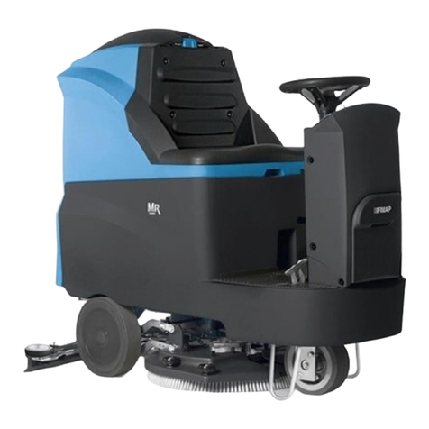
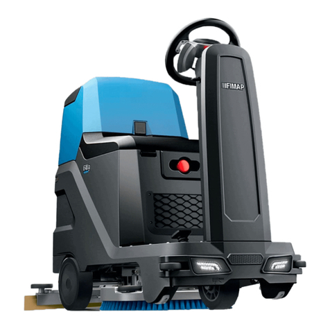
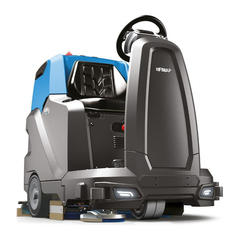
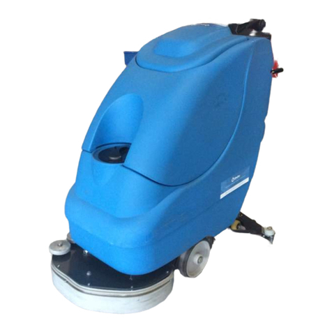
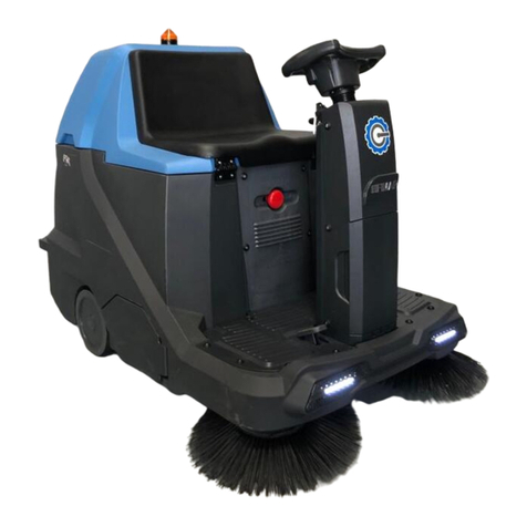
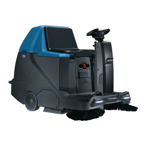
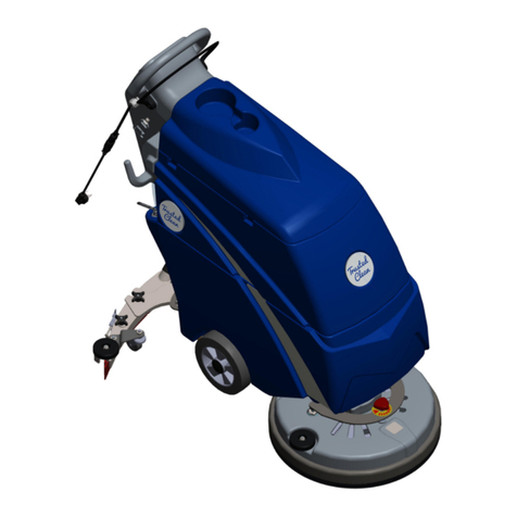
Fimap MXR Instruction manual

WORKSHOP HANDBOOK
MXR
Version: AA
Date: January 15, 2014
Document Number:10045983/ATE

Contents
I Product Introduction 4
1 Serial Number and Technical Support 5
1.1 The Serial Tag ................................. 5
1.2 Serial Tag location ............................... 5
2 Main Technical Features 6
II Anomalies Resolution Guide 8
3 Trouble-shooting for the most common anomalies 9
3.1 Electrical system: what to do if. . . ...................... 9
3.2 Mechanical scrubbing system: what to do if. . . .............. 12
3.3 Drying system: what to do if. . . ....................... 13
3.4 Frame and traction system: what to do if. . . ................ 15
3.5 Solution delivery system: what to do if. . . ................. 16
4 Disassembling Procedures 17
4.1 Electrical Installation ............................. 18
4.2 Mechanical Friction System ......................... 20
4.3 Drying System ................................. 22
4.4 Frame and Traction System ......................... 25
4.5 Solution Delivery System ........................... 27
III Machine Description 30
5 Electrical System 31
5.1 Structure .................................... 31
5.2 Description ................................... 31
5.3 Location of Electrical components ...................... 32
5.4 Adjustments .................................. 40
5.5 Maintenance and Checks ........................... 43
5.6 Alarm Table ................................... 44
5.7 Menu tables ................................... 45
5.8 Technical Features ............................... 51
5.9 Recommended Spare Parts .......................... 51
2

6 Mechanical Rubbing System 52
6.1 Structure .................................... 52
6.2 Description: ................................... 52
6.3 Adjustments .................................. 53
6.4 Maintenance and checks ........................... 53
6.5 Technical Features ............................... 56
6.6 Consumable Spare Parts ........................... 56
6.7 Recommended Spare parts .......................... 56
7 Drying System 57
7.1 Structure .................................... 57
7.2 Description ................................... 57
7.3 Adjustments .................................. 58
7.4 Maintenance and Checks ........................... 59
7.5 Technical Features ............................... 63
7.6 Consumable Spare Parts ........................... 63
7.7 Recommended Spare Parts .......................... 63
8 Machine Frame and Traction System 64
8.1 Structure .................................... 64
8.2 Description ................................... 64
8.3 Adjustments .................................. 65
8.4 Maintenance and Checks ........................... 66
8.5 Technical Features ............................... 68
8.6 Consumable spare parts ........................... 68
8.7 Suggested spare parts ............................. 68
9 Cleaning Solution Supply System 69
9.1 Structure .................................... 69
9.2 Description: ................................... 69
9.3 Maintenance and Checks ........................... 70
9.4 Technical Features ............................... 72
9.5 Recommended Spare parts .......................... 72
IV Accessories and Add-On 73
10 Accessories 74
10.1Accessories List ................................ 74
10.2Blinking Kit - 222471 ............................. 74
10.3Onboard Charger Kit - 222386 ........................ 76
10.4Splashguard Kit - 222480 .......................... 77
10.5Cleaning Accessories Kit - 222472 ..................... 78
10.6Consumable Spare Parts ........................... 80
Part I
Product Introduction
4

1-5
Chapter 1
Serial Number and Technical Support
1.1 The Serial Tag
1.2 Serial Tag location
To have access to the Serial Tag is necessary to open the glove box on the steering
column.
The Serial Number is an extremely important information which has to be provided
each time a Technical Support is required or is necessary to buy spare parts or
accessories. The serial number is the only way to identify the machine by model,
production date type equipments in general.
5

2-6
Chapter 2
Main Technical Features
Technical Data
TECHNICAL DESCRIPTION U/M Mxr
Maximum Ramp Gradient % 8
Steering Diameter mm 3680
Machine Length mm 1265
Machine length with optional storage compartment mm 1400
Machine Height mm 1030
Machine height with optional blinking kit mm 1070
Machine Width (without squeegee) mm 600
Machine Width
(without squeegee) with optional toolbox kit
mm 620
Wheel Base mm 730
Wheel Track mm 520
Footrest height from the ground mm 230
Seat height from the footrest mm 466
Handlebar distance from the back seat mm 530
6

2-7
Weigths and Pressures1
TECHNICAL DESCRIPTION U/M Mxr
Machine Weight (empty and without batteries) kg 110.4
Gross Weight of the machine in work conditions
(machine + batteries + water + operator)
kg 332.4
Weight front wheel kg 80.00 ÷116.00
Front wheel touching surface cm211.95 ÷14.14
Front wheel pressure kg
cm26.58 ÷8.21
Weight rear right wheel kg 84.03 ÷120.80
Rear right wheel touching surface cm27.42 ÷10.28
Rear right wheel pressure kg
cm210.44 ÷11.75
Weight rear left wheel kg 85.50 ÷123.40
Rear left wheel touching surface cm28.62 ÷10.35
Rear left wheel pressure kg
cm28.40 ÷12.87
1Weight and Pressures depends on how much water there is in the tanks and on what type of battery the
machine fits.

2-8
Part II
Anomalies Resolution Guide
8

3-9
Chapter 3
Trouble-shooting for the most common
anomalies
3.1 Electrical system: what to do if. . .
The machine doesn’t switch on
1 The emergency button is pressed ⇒Release the emergency button.
2 The key is in position 0 ⇒Rotate the key in position I.
3 The key switch is not properly con-
nected
⇒Restore the proper connections.
4 The key switch doesn’t work ⇒Replace the key switch (see section 4.1.1
at page 18).
9

3-10
The batteries don’t work properly
1 The batteries are not properly con-
nected
⇒Restore the proper battery connec-
tions.
2 The batteries are discharged ⇒Perform a complete charge cycle.
3 Battery terminal are oxidized ⇒Disconnect the batteries, clean the
batteries terminals and reconnect
properly the batteries.
4 With the machine in working con-
ditions one battery has a voltage
lower (difference higher than 2 V)
than the other ones
⇒Replace the battery with lower volt-
age.
5 The fuse on the loop wire is dam-
aged
⇒Check for possible short circuits, If
not present replace the loop wire.
6 The power wires are damaged ⇒Replace the damaged wires.
7 The battery charger is not properly
adjusted
⇒Adjust properly the battery charger.
8 The battery charger doesn’t work ⇒Check the proper section (see section 3.1
at page 10).
The battery charger doesn’t work
1 The battery charger is not con-
nected to the power supply
⇒Connect the charger to a supplied
electric socket.
2 The battery charger is not con-
nected to the batteries
⇒Connect the charger to the batteries.
3 The battery charger has one or
more lights (or LEDs) blinking con-
tinuously
⇒The battery charger is in error con-
ditions, verify the alarm tables and
solve the issue by following the re-
lated instructions (see section 5.3.8 at page
40).
4 The battery charger is properly con-
nected but it doesn’t switch on
⇒Replace the battery charger.

3-11
The display shows an alarm message
1 The display shows an alarm mes-
sage
⇒Check what alarm message is
shown and solve the related issue
by following the proper instructions
(see section 5.6.1 at page 44).
The machine has a very limited working autonomy
1 The batteries connections are oxi-
dized
⇒Unplug the connection wires, wash
the wire connections with water and
reconnect them protecting them with
grease.
2 When the machine is working a bat-
tery voltage is lower and lower than
the other batteries (The difference is
bigger than 2V)
⇒Replace the battery with the lower
voltage.
3 The battery charger is not properly
adjusted
⇒Verify the type of battery in use and
adjust the battery charger properly
following the instructions (see section
5.4.3 at page 41).
4 The BDI (Battery Discharge Indica-
tor) is not properly adjusted
⇒Verify the type of battery used on
the machine and adjust properly the
BDI.
5 Batteries have been working for
several cycles
⇒Replace the batteries.

3-12
3.2 Mechanical scrubbing system: what to do if. . .
The machine doesn’t clean well
1 The machine is switched off ⇒Switch on the machine.
2 The machine doesn’t switch on ⇒Refer to the proper section (see section
3.1 at page 9).
3 The machine is not in working con-
dition
⇒Switch on the machine.
Lower the scrubbing base.
Press the traction pedal.
4 The display shows an alarm mes-
sage
⇒Check what alarm message is
shown and solve the related issue
by following the proper instructions
(see section 5.6.1 at page 44).
5 The brush rotates in opposite way ⇒Check the motor connections.
6 The brush deck motor is not sup-
plied
⇒Verify the motor connections.
7 The microswitch of the scrubbing
base lifting lever doesn’t work
⇒Replace the microswitch (see section 4.1.6
at page 19).
8 The microswitch of the traction
pedal doesn’t work
⇒Replace the microswitch (see section 4.1.4
at page 19).
9 The brush is not properly engaged ⇒Release and engage properly the
brush.
10) The solution flow rate is not correct
or not enough
⇒Refer to the proper section.
The brush deck doesn’t move
1 The brush deck Lever doesn’t move ⇒Check that there are no mechani-
cal obstacles to the movement of the
lever.
2 The lever moves but the brush deck
doesn’t move
⇒Check that the lifting cable runs in
its sheath and the chain is free to
move. Check that the brush deck lift-
ing arms are free to move.
3 The brush deck is lowered but it
doesn’t touch the ground
⇒Check the settings of the lifting ca-
ble.

3-13
3.3 Drying system: what to do if. . .
The machine doesn’t dry well
1 The machine is switched off ⇒Switch on the machine.
2 The machine doesn’t switch on ⇒Refer to the proper section (see section
3.1 at page 9).
3 The squeegee is lifted up from the
floor
⇒Lower down the squeegee.
4 The squeegee rubber blades are
worn out or broken
⇒Rotate or replace the squeegee rub-
ber blades.
5 The recovery tank is full ⇒Empty the recovery tank following
the proper procedure.
6 The squeegee is not properly ad-
justed
⇒Adjust the squeegee properly follow-
ing the proper procedure (see section 7.3.1
at page 58).
7 The squeegee vacuum chamber is
stuck or dirty
⇒Clean the squeegee vacuum cham-
ber.
8 The squeegee adapter is stuck or
dirty
⇒Clean the squeegee adapter.
9 The vacuum hose is stuck or bro-
ken
⇒Clean or replace the vacuum hose.
10 The vacuum hose is not properly
fitted in
⇒Connect the vacuum hose properly.
11 The vacuum filter is dirty or stuck ⇒Disassemble and clean the vacuum
filter.
12 The vacuum cover is not well posi-
tioned or is missing
⇒Position properly the vacuum cover.
13 The vacuum cover gasket doesn’t
adhere properly
⇒Replace the vacuum cover gasket.

3-14
The vacuum motor doesn’t work properly
1 The vacuum motor is switched off ⇒Switch on the vacuum motor.
2 The vacuum motor is not powered
properly
⇒Check the power connections on the
vacuum motor.
3 The microswitch on the squeegee
lifting lever doesn’t work
⇒Replace the microswitch.
4 The display shows an alarm mes-
sage
⇒Check what alarm message is
shown and solve the related issue
by following the proper instructions
(see section 5.6.1 at page 44).
5 The vacuum motor carbon brushes
are worn out
⇒Replace the vacuum motor carbon
brushes.
6 The vacuum motor is supplied but
it doesn’t work
⇒Replace the vacuum motor.
The squeegee doesn’t move
1 The squeegee Lever doesn’t move ⇒Check that there are no mechani-
cal obstacles to the movement of the
lever.
2 The lever moves but the squeegee
doesn’t move
⇒Check that the lifting cable runs in
its sheath and the chain and the
rear lever is free to move.
3 The squeegee is lowered but it
doesn’t touch the ground
⇒Check the settings of the lifting ca-
ble.

3-15
3.4 Frame and traction system: what to do if. . .
The traction motor doesn’t work properly
1 The machine is switched off ⇒Switch on the machine.
2 The machine doesn’t switch on ⇒Check the proper section (see section 3.1
at page 9).
3 The batteries are discharged ⇒Connect the battery charger and
perform a complete charge cycle.
4 The operator is not sitting on the
seat
⇒The operator must sit on the seat.
5 The operator is sitting on the seat ⇒Check and / or replace the deadman
seat microswitch.
6 The pedal is not pressed ⇒Press the pedal depending on the re-
quired speed.
7 The pedal is pressed ⇒Check and / or replace the poten-
tiometer or the microswitch inside
the pedal.
8 The display shows an alarm mes-
sage
⇒Check what alarm message is
shown and solve the related issue
by following the proper instructions
(see section 5.6.1 at page 44).
9 The brush deck motor is not sup-
plied
⇒Verify the motor connections.
10 The electrobrake doesn’t disengage ⇒Check the connections of the electro-
brake.

3-16
3.5 Solution delivery system: what to do if. . .
The delivered solution is not correct or not enough
1 The machine is switched off ⇒Switch on the machine.
2 The machine doesn’t switch on ⇒Refer to the proper section (see section
3.1 at page 9).
3 The solution tank is empty ⇒Fill up the solution tank.
4 The proportional valve for the solu-
tion flow adjustment is completely
closed
⇒Open the proportional valve to the
desired position.
5 The hose that connects the solution
tank to the filter is stuck
⇒Clean the hose.
6 The solution filter is stuck ⇒Clean the solution filter.
7 The brush deck is not in working
conditions
⇒Lower the brush deck to the floor
Press the traction pedal to start the
washing.
8 The solenoid valve doesn’t work ⇒Check the solenoid valve connec-
tions and, if necessary, replace it (see
section 4.5.4 at page 28).
9 The display shows an alarm mes-
sage
⇒Check what alarm message is
shown and solve the related issue
by following the proper instructions
(see section 5.6.1 at page 44).
10 The detergent doesn’t fit the type of
dirt
⇒Replace the detergent with a proper
one.

4-17
Chapter 4
Disassembling Procedures
WARNING:BEFORE TO PERFORM ANY OPERATION DESCRIBED BELOW VERIFY THAT
THE MACHINE TANKS ARE COMPLETELY EMPTY,THE MACHINE HAS TO BE TURNED
OFF. DISCONNECT THE BATTERIES AND REMOVE THEM FROM THE MACHINE. AT LAST,
VERIFY THAT THE PARKING BRAKE IS ENGAGED AND THE MACHINE IS IN A TOTALLY
SAFE CONDITION.
17

4-18
4.1 Electrical Installation
4.1.1 Key Switch
•Put the machine in safe conditions.
•Remove the screws that secure the
front carter to the steering column
(see fig. 4.1.1-1) (see fig. 4.1.1-2).
•Disconnect the wires connected to
the key switch.
•Unscrew the ring nut that secures
the key switch to the steering col-
umn (see fig. 4.1.1-3).
•Remove the key switch.
4.1.1-1 4.1.1-2
4.1.1-3
4.1.2 Control Card
•Put the machine in safe conditions.
•Remove the screws that secure the
upper and lower part of the steering
wheel (see fig. 4.1.2-4).
•Separate the top part from the bot-
tom part.
•Disconnect the communication ca-
ble between the Control card and the
Main card.
•Unscrew the screws on the control
card from the top part and remove
the card (see fig. 4.1.2-5).
4.1.2-4 4.1.2-5
4.1.3 Main Card
•Put the machine in safe conditions.
•Remove the screws to remove the
footrest.
•Remove the screws to remove the
electrical system cover (see fig. 4.5.1-56).
4.1.3-6
•Disconnect the electrical wiring of
the emergency button and of the
Main card.
•Remove the screws that secure the
card to the support bracket.
•Remove the card.

4-19
4.1.4 Traction Pedal
•Put the machine in safe conditions.
•Remove the screws to remove the
footrest.
•Release the footswitch connector
and unscrew the two screws holding
the pre-assembly pedal.
•Remove the pedal.
4.1.5 Microswitch
•Put the machine in safe conditions.
•Remove the screws that secure the
front carter to the steering column.
•Disconnect the wires connected to
the microswitch.
•To remove the microswitch, unscrew
the two screws and remove the de-
vice.
4.1.6 Dead Man Switch (Seat
microswitch)
•Put the machine in safe conditions.
•Unscrew the screws to remove the
electrical system cover (see fig. 4.5.1-56).
•Unscrew the lower screws that fix
the seat (see fig. 4.1.6-8).
•Unscrew the rear screws that fix the
seat (see fig. 4.1.6-9).
•Remove the seat from the machine
(see fig. 4.1.6-10).
•Remove the switch connecting
joints.
•Remove the dead man Switch.

4-20 4.1.6-7 4.1.6-8
4.1.6-9 4.1.6-10
4.2 Mechanical Friction
System
4.2.1 Brush Deck Assembly
•Release the brush from the Brush
Deck.
•Put the machine in safe conditions.
•Make sure that the electrobrake is
enabled.
•Lower the brush deck to the floor.
•Remove the lift arms from the frame.
•Disconnect the electrical connector
of the brush motor and the electric
connector of the solenoid valve.
•Disconnect the solution supply
hose.
•Disconnect the lift chain from the
brush plate.
•Lift the front wheel in order to lift the
front part of the machine of about
20cm.
•Pull off the brush deck sideways to
the machine.
4.2.2 Brush Coupling Flange
•Put the machine in safe conditions.
•Disassemble the Brush Deck from
the machine (see section 4.2.1 at page 20).
•Unscrew the Coupling Flange rotat-
ing it in the same direction as the
brush in standard working condi-
tions.
•Proceed at reverse to refit the part.
Note: Before to refit the part lubricate
the thread in order to prevent blockings
because of dirt or oxide.
4.2.2-11
4.2.3 Brush Motor
•Put the machine in safe conditions.
•Disassemble the Brush Deck from
the machine (see section 4.2.1 at page 20).
•Unscrew the Coupling Flange from
the motor shaft (see section 4.2.2 at page 20).
•Disconnect the electrical connector
of the motor.
•Disconnect the water hose from the
motor (see fig. 4.5.1-58).
•Unscrew the 4 fixing screws and re-
move the motor (see fig. 4.2.3-13).
•Proceed at reverse to refit the part.
Note: Use the thread lock liquid on the
screw during the assembling.
Other manuals for MXR
1
Table of contents
Other Fimap Floor Machine manuals

Fimap
Fimap MMg base Installation instructions

Fimap
Fimap ENJOY 360 Guide

Fimap
Fimap FM4017 User manual

Fimap
Fimap MAGNA 85 BS Reference guide

Fimap
Fimap Magna 1300 User manual

Fimap
Fimap 1500 S-V User manual

Fimap
Fimap FS50 B-BT User manual

Fimap
Fimap FS700 H User manual

Fimap
Fimap MR60 User manual

Fimap
Fimap GENIE BS User manual

Fimap
Fimap MAGNA PLUS User manual

Fimap
Fimap BMg Sanitizer User manual

Fimap
Fimap FM1500 S User manual

Fimap
Fimap FM43 ORBITALE User manual

Fimap
Fimap FM43 F User manual

Fimap
Fimap FM43 ORB User manual

Fimap
Fimap IMx Instruction manual

Fimap
Fimap FSR B User manual

Fimap
Fimap GAMMA 66 User manual

Fimap
Fimap Minny 420 Installation instructions