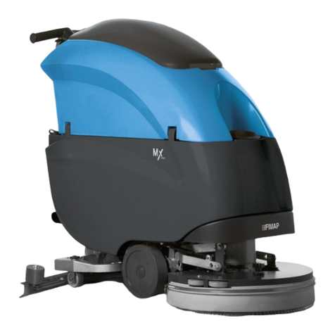
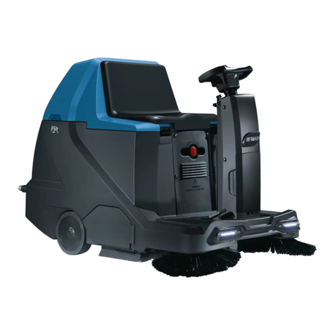
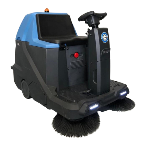
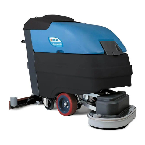
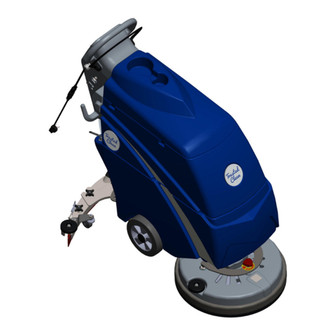
Fimap IMx Instruction manual

WORKSHOP HANDBOOK
IMx
Version: AB
Date: October 29, 2013
Document Number:10043430/ATE

Updates from the previous version.
Section Page Since Serial Number
4.1.14 21 213009132 =⇒
5.6 49 213008830 =⇒
5.14.3 58 213008830 =⇒
5.5.4 48 213009146 =⇒
10.4 86 -=⇒

Contents
I Product Introduction 4
1 Serial Number and Technical Support 5
1.1 The Serial Tag ................................. 5
1.2 Serial Tag location ............................... 5
2 Main Technical Features 6
II Anomalies Resolution Guide 7
3 Trouble-shooting for the most common anomalies. 8
3.1 Electrical system: what to do if. . . ...................... 8
3.2 Frame and traction system: what to do if. . . ................ 11
3.3 Mechanical scrubbing system: what to do if. . . .............. 12
3.4 Solution delivery system: what to do if. . . ................. 13
3.5 Drying system: what to do if. . . ....................... 14
4 Disassembling Procedures 16
4.1 Electrical Installation ............................. 17
4.1.1 Tools needed .............................. 17
4.1.2 Function Dashboard IMx B/BT ................... 17
4.1.3 Display Card IMx B/BT ........................ 17
4.1.4 Potentiometer IMx B/BT ....................... 17
4.1.5 Power Card IMx B/BT ......................... 18
4.1.6 Rear Dashboard IMx B/BT ...................... 18
4.1.7 Buzzer IMx B/BT ............................ 19
4.1.8 Key Switch ............................... 19
4.1.9 BDI (Battery Discharge Indicator) IMx BB ............. 19
4.1.10Function Switch IMx BB ....................... 20
4.1.11Vacuum Motor Contactor IMx BB .................. 20
4.1.12Brush Motor Contactor IMx BB ................... 20
4.1.13Brush Release Switch IMx BB .................... 21
4.1.14Dead Man Switch ........................... 21
4.1.15Battery Charger IMx CB ........................ 22
4.2 Mechanical Friction System ......................... 23
4.2.1 Tools needed .............................. 23
4.2.2 Brush Deck Assembly ......................... 23
4.2.3 Brush Coupling Flange ........................ 24
4.2.4 Brush Stopper Spring ......................... 24
3

4.2.5 Brush Motor .............................. 24
4.2.6 Bumper Wheel ............................. 25
4.3 Drying System ................................. 26
4.3.1 Squeegee ................................ 26
4.3.2 Squeegee Adapter ........................... 26
4.3.3 Squeegee Support ........................... 26
4.3.4 Squeegee adjustment wheels ..................... 27
4.3.5 Squeegee Rotation Arm ........................ 27
4.3.6 Vacuum Hose .............................. 28
4.3.7 Recovery Tank ............................. 28
4.3.8 Drain Hose ............................... 29
4.3.9 Vacuum Filter .............................. 29
4.3.10Vacuum Motor ............................. 29
4.3.11Squeegee Lifting Chain ........................ 30
4.3.12Squeegee Lifting Lever ......................... 31
4.4 Frame and Traction System ......................... 32
4.4.1 Wheels .................................. 32
4.4.2 Drive Shaft IMx BT ........................... 32
4.4.3 Traction Gearmotor IMx BT ...................... 32
4.4.4 Free Shaft IMx B-BB .......................... 32
4.4.5 Parking Wheel ............................. 33
4.4.6 Parking Brake IMx BT ......................... 34
4.5 Solution Delivery System ........................... 35
4.5.1 Solution Tank .............................. 35
4.5.2 Hoses .................................. 36
4.5.3 Solution Filter ............................. 36
4.5.4 Water Valve ............................... 36
4.5.5 Solenoid Valve ............................. 37
III Machine Description 38
5 Electrical System 39
5.1 Structure IMx BB ............................... 39
5.2 Description IMx BB .............................. 39
5.3 Structure IMx B/BT .............................. 40
5.4 Description IMx B/BT ............................. 40
5.5 Location of Electrical components ...................... 41
5.5.1 IMx BB .................................. 41
List of Components .......................... 42
5.5.2 IMx B/BT ................................ 43
List of Components .......................... 44
5.5.3 Main Card (IMx B/BT) ......................... 45
5.5.4 Dashboard ............................... 45
Functions and Commands ...................... 46
Entry into “Operator Menu” and “Advanced Menu” ........ 46
Operator Menu ............................. 47
Change a Parameter (in the Operator Menu) ............ 47

Advanced Menu ............................ 48
Change a Parameter (in the Advanced Menu) ........... 48
Parameters Reset ............................ 48
Check/Monitor Function ....................... 48
5.5.5 Control Card .............................. 49
5.6 Safety Microswitch ............................... 49
5.7 Potentiometer (IMx BT only) ......................... 49
5.8 Hourmeter (IMx BB only) ........................... 50
5.9 Charger ..................................... 50
5.10Batteries ..................................... 50
5.11Adjustments .................................. 51
5.11.1Battery Control Card (IMx BB only) ................. 51
5.11.2Charger (CB) .............................. 51
Charging curve SetUp ......................... 52
Error Codes of Charger ........................ 52
5.11.3ECO Function (solo IMx B/BT) .................... 52
5.12Maintenance and Checks ........................... 53
5.12.1Electrical System ............................ 53
Checks .................................. 53
5.12.2Batteries ................................. 53
Checks .................................. 53
5.13Alarm Table (IMx B/BT only) ......................... 54
5.13.1Alarms .................................. 54
Alarms of Overcurrent and Temperature .............. 54
Traction Alarms ............................ 54
General Alarms ............................. 54
5.14Menu Tables (IMx B/BT only) ........................ 55
5.14.1Menu Tree ................................ 55
5.14.2Working Menu ............................. 56
5.14.3Advanced Menu ............................ 56
General Sets .............................. 57
Brushes Sets .............................. 57
Pumps Sets ............................... 58
Vacuum Sets .............................. 58
Traction Sets .............................. 59
Check / Monitor ............................ 60
5.15Technical Features ............................... 61
5.16Recommended Spare Parts .......................... 61
6 Mechanical Rubbing System 62
6.1 Structure .................................... 62
6.2 Description ................................... 62
6.3 Adjustments .................................. 63
6.3.1 Adjustment system .......................... 63
6.4 Maintenance and checks ........................... 63
6.4.1 Motor .................................. 63
Checks: ................................. 63
Maintenance: .............................. 63
6.4.2 Brass bushings ............................. 64
Checks: ................................. 64
Maintenance: .............................. 64
6.4.3 Bumping Wheel ............................ 65
Checks: ................................. 65
6.4.4 Brushes Base .............................. 65
Checks: ................................. 65
6.4.5 Brush coupling flange ......................... 65
Checks: ................................. 65
6.4.6 Fixing and adjustment plate ..................... 65
Checks: ................................. 65
6.5 Technical Features ............................... 66
6.6 Consumable Spare Parts ........................... 66
6.7 Recommended Spare parts .......................... 66
7 Drying System 67
7.1 Structure .................................... 67
7.2 Description ................................... 67
7.3 Adjustments .................................. 68
7.3.1 Squeegee Support ........................... 68
Procedure ................................ 68
7.4 Maintenance and Checks ........................... 69
7.4.1 Squeegee ................................ 69
Checks .................................. 69
Maintenance .............................. 69
7.4.2 Squeegee Support ........................... 69
Checks .................................. 69
Maintenance .............................. 70
7.4.3 Vacuum Hose .............................. 70
Checks .................................. 70
7.4.4 Filter and Floater ............................ 70
Checks .................................. 70
Maintenance .............................. 70
7.4.5 Recovery Tank ............................. 71
Checks .................................. 71
7.4.6 Vacuum Motor ............................. 71
Checks .................................. 71
Maintenance .............................. 71
7.4.7 Drain Hose ............................... 72
Checks .................................. 72
7.5 Technical Features ............................... 73
7.6 Consumable Spare Parts ........................... 73
7.7 Recommended Spare Parts .......................... 73
8 Machine Frame and Traction System 74
8.1 Structure .................................... 74
8.2 Description ................................... 74
8.3 Adjustments .................................. 75

8.3.1 Parking Brake Lever (IMx BT only) .................. 75
Procedure ................................ 75
8.4 Maintenance and Checks ........................... 75
8.4.1 Wheels .................................. 75
Checks .................................. 75
Maintenance .............................. 75
8.4.2 Traction Motor (Only IMx BT model) ................. 75
Checks .................................. 75
Maintenance .............................. 76
8.5 Technical Features ............................... 77
8.6 Consumable spare parts ........................... 77
8.7 Suggested spare parts ............................. 77
9 Cleaning Solution Supply System 78
9.1 Structure .................................... 78
9.2 Description ................................... 78
9.3 Maintenance and Checks ........................... 79
9.3.1 Solution Tank .............................. 79
Controls: ................................ 79
9.3.2 Hoses .................................. 79
Checks: ................................. 79
9.3.3 Water Valve ............................... 79
Checks: ................................. 79
9.3.4 Clean Water Filter ........................... 79
Checks: ................................. 79
9.3.5 Solenoid Valve ............................. 80
Checks: ................................. 80
9.3.6 Distributor ............................... 80
Controls: ................................ 80
9.4 Technical Features ............................... 81
9.5 Recommended Spare parts .......................... 81
IV Accessories and Add-On 82
10 Accessories 83
10.1Accessories List ................................ 83
10.2Splashguard Kit - 223227 .......................... 83
10.2.1Description ............................... 83
10.2.2Tools needed for the installation ................... 83
10.2.3Machine Preparation .......................... 83
Installing instructions IMx BT .................... 84
Installing Instructions IMx B/BB .................. 84
10.3Onboard Charger Kit - 223232 ........................ 85
10.3.1Description ............................... 85
10.3.2Tools needed for the installation ................... 85
10.3.3Machine Preparation .......................... 85
10.3.4Installing instructions ......................... 85
10.4Extension Handlebar Kit - 223457 ..................... 86

10.4.1Description ............................... 86
10.4.2Tools needed for the installation ................... 86
10.4.3Machine Preparation .......................... 86
Installing instructions ......................... 87
10.5Consumable Spare Parts ........................... 88

Part I
Product Introduction
9

1-10
Chapter 1
Serial Number and Technical Support
1.1 The Serial Tag
1.2 Serial Tag location
To have access to the Serial Tag is necessary to remove the recovery tank.
The Serial Number is an extremely important information which has to be provided
each time a Technical Support is required or is necessary to buy spare parts or
accessories. The serial number is the only way to identify the machine by model,
production date type equipments in general.
10

2-11
Chapter 2
Main Technical Features
TECHNICAL DESCRIPTION U/M IMx BB IMx B IMx BT
Maximum Ramp Gradient % 2 2 2
Steering Diameter mm 1700 1700 1700
Machine Length mm 1200 1200 1200
Machine Height mm 1030 1030 1030
Machine Width (without squeegee) mm 570 570 570
Machine Weight (empty and without batter-
ies)
kg 69 69 76
Gross Weight of the machine in work condi-
tions (machine + batteries + water)
kg 163 163 170
Weigths and Pressures1
Weight on front right wheel kg 51.90 ÷74.00
Touching surface of the front right wheel cm28.41 ÷10.32
Pressure made by the front right wheel kg
cm25.76 ÷7.83
Weight on front left wheel kg 46.10 ÷69.30
Touching surface of the front left wheel cm27.79 ÷9.66
Pressure made by the front left wheel kg
cm25.42 ÷8.54
Weight on rear wheel kg 10.50 ÷44.30
Touching surface of the rear wheel cm20.41 ÷0.91
Pressure made by the rear wheel kg
cm216.49 ÷51.64
1Weight and Pressures depends on how much water there is in the tanks and on what type of battery the
machine fits.
11

2-12
Part II
Anomalies Resolution Guide
12

3-13
Chapter 3
Trouble-shooting for the most common
anomalies.
3.1 Electrical system: what to do if. . .
The machine doesn’t switch on
1) (Only B-BT) The key is in position 0 ⇒Rotate the key in position I.
2) (Only BB) The main switch is in po-
sition 0
⇒Push the switch in position I or II.
3) (Only B-BT) The key switch is not
properly connected
⇒Restore the proper connections.
4) (Only BB) The main switch is not
properly connected
⇒Restore the proper connections.
5) (Only B-BT) The key switch doesn’t
work
⇒Replace the key switch (see section 4.1.8
at page 19).
6) (Only BB) The main switch doesn’t
work
⇒Replace the main switch (see section
4.1.10 at page 20).
7) The machine is not powered prop-
erly
⇒Refer to the proper section (see section
3.1 at page 9).
13

3-14
The batteries don’t work properly
1) The batteries are not properly con-
nected
⇒Restore the proper battery connec-
tions.
2) Battery are discharged ⇒Perform a complete charge cycle.
3) Battery terminal are oxidized ⇒Disconnect the batteries, clean the
batteries terminals and reconnect
properly the batteries.
4) With the machine in working con-
ditions one battery has a voltage
lower (difference higher than 2 V)
than the other ones
⇒Replace the battery with lower volt-
age.
5) The fuse on the loop wire is dam-
aged
⇒Check for possible short circuits, If
not present replace the loop wire.
6) The power wires are damaged ⇒Replace the damaged wires.
7) The battery charger is not properly
adjusted
⇒Adjust properly the battery charger.
8) The battery charger doesn’t work ⇒Check the proper section (see section 3.1
at page 9).
The battery charger doesn’t work
1) The battery charger is not con-
nected to the power supply
⇒Connect the charger to a supplied
electric socket.
2) The battery charger is not con-
nected to the batteries
⇒Connect the charger to the batteries.
3) The battery charger has one or
more lights (or LEDs) blinking con-
tinuously
⇒The battery charger is in error con-
ditions, verify the alarm tables and
solve the issue by following the re-
lated instructions (see section 5.9 at page 50).
4) The battery charger is properly con-
nected but it doesn’t switch on
⇒Replace the battery charger.

3-15
(Only B-BT) The display shows an alarm message
1) The display shows an alarm mes-
sage
⇒Check what alarm message is
shown and solve the related issue
by following the proper instructions
(see section 5.13.1 at page 54).
The machine has a very limited working autonomy
1) The batteries connections are oxi-
dized
⇒Unplug the connection wires, wash
the wire connections with water and
reconnect them protecting them with
grease.
2) When the machine is working a bat-
tery voltage is lower and lower than
the other batteries (The difference is
bigger than 2V)
⇒Replace the battery with the lower
voltage.
3) The battery charger is not properly
adjusted
⇒Verify the type of battery in use and
adjust the battery charger properly
following the instructions (see section 5.9
at page 50).
4) The BDI (Battery Discharge Card) is
not properly adjusted
⇒Verify the type of battery used on
the machine and adjust properly the
BDI.
5) Batteries have been working for
several cycles
⇒Replace the batteries.

3-16
3.2 Frame and traction system: what to do if. . .
(Only BT) The traction motor doesn’t work properly
1) The machine is switched off ⇒Switch on the machine.
2) The machine doesn’t switch on ⇒Check the proper section (see section 3.1
at page 8).
3) The display shows an error mes-
sage
⇒Check the proper section.
4) The dead man lever is not pressed ⇒Push the dead man lever.
5) The dead man switch is not prop-
erly connected
⇒Restore the proper connection to the
dead man switch.
6) The dead man switch doesn’t work ⇒Replace the dead man switch.
7) The speed adjuster is at its mini-
mum
⇒Rotate the speed adjuster to in-
crease the speed.
8) The motor is not supplied ⇒Verify the motor connections.
9) The traction motor is supplied but
it doesn’t work
⇒Replace the traction motor.
The machine doesn’t move straight
1) (Only BT) The parking brake is en-
gaged
⇒Release the brake.
2) The brush is not properly engaged ⇒Release the brush and engage it
properly.
3) The brush deck is not properly ad-
justed
⇒Adjust properly the brush deck.

3-17
3.3 Mechanical scrubbing system: what to do if. . .
The machine doesn’t clean well
1) The machine is switched off ⇒Switch on the machine.
2) The machine doesn’t switch on ⇒Refer to the proper section (see section
3.1 at page 8).
3) (Only B-BT) The display shows an
alarm message
⇒Refer to the proper section (see section
3.1 at page 8).
4) (Only B-BT) The switch ”Auto” is
not pressed
⇒Press the ”Auto” switch.
5) The dead man switch doesn’t work ⇒Replace the dead man switch (see sec-
tion 4.1.14 at page 21).
6) The brush deck motor is not sup-
plied
⇒Verify the motor connections.
7) The brush rotates in opposite way ⇒Check the motor connections.
8) The brushdeck is lifted from the
floor
⇒Tilt down the machine to let the
brush touch the floor.
9) The brush is not properly engaged ⇒Release and engage properly the
brush.
10) The solution flow rate is not correct
or not enough
⇒Refer to the proper section.

3-18
3.4 Solution delivery system: what to do if. . .
The delivered solution is not correct or not enough
1) The machine is switched off ⇒Switch on the machine.
2) The machine doesn’t switch on ⇒Refer to the proper section (see section
3.1 at page 8).
3) The solution tank is empty ⇒Fill up the solution tank.
4) The proportional valve for the solu-
tion flow adjustment is completely
closed
⇒Open the proportional valve to the
desired position.
5) (Only B-BT) The water flow is ad-
justed at minimum
⇒Increase the water flow adjustment.
6) The solenoid valve doesn’t work ⇒Check the solenoid valve connec-
tions and, if necessary, replace it (see
section 4.5.5 at page 37).
7) The solution filter is stuck ⇒Clean the solution filter.
8) The display shows an alarm mes-
sage
⇒Refer to the proper section (see section
5.13.1 at page 54).
9) The detergent doesn’t fit the type of
dirt
⇒Replace the detergent with a proper
one.

3-19
3.5 Drying system: what to do if. . .
The machine doesn’t dry well
1) The machine is switched off ⇒Switch on the machine.
2) The machine doesn’t switch on ⇒Refer to the proper section (see section
3.1 at page 8).
3) The vacuum motor is switched off ⇒Switch on the vacuum motor.
4) The vacuum motor doesn’t switch
on
⇒Refer to the proper section (see section
3.5 at page 15).
5) The machine is in ”ECO” mode ⇒Set up the machine as per standard
configuration.
6) The squeegee is lifted up from the
floor
⇒Lower down the squeegee.
7) The squeegee rubber blades are
worn out or broken
⇒Rotate or replace the squeegee rub-
ber blades.
8) The recovery tank is full ⇒Empty the recovery tank following
the proper procedure.
9) The squeegee is not properly ad-
justed
⇒Adjust the squeegee properly follow-
ing the proper procedure (see section 7.3.1
at page 68).
10) The squeegee vacuum chamber is
stuck or dirty
⇒Clean the squeegee vacuum cham-
ber.
11) The squeegee adapter is stuck or
dirty
⇒Clean the squeegee adapter.
12) The vacuum hose is stuck or bro-
ken
⇒Clean or replace the vacuum hose.
13) The vacuum hose is not properly
fitted in
⇒Connect the vacuum hose properly.
14) The intake manifold is stuck or bro-
ken
⇒Clean or replace the intake manifold.
15) The intake manifold is not properly
connected
⇒Connect the intake manifold prop-
erly.
16) The vacuum filter is dirty or stuck ⇒Disassemble and clean the vacuum
filter.
17) The vacuum cover is not well posi-
tioned or is missing
⇒Position properly the vacuum cover.
18) The vacuum cover gasket doesn’t
adhere properly
⇒Replace the vacuum cover gasket.

3-20
The vacuum motor doesn’t work properly
1) The vacuum motor is not powered
properly
⇒Check the power connections on the
vacuum motor.
2) (Only BB) The vacuum motor
switch doesn’t work
⇒Replace the vacuum motor switch.
3) (Only B-BT) The display shows an
alarm message
⇒Refer to the proper section (see section
5.13.1 at page 54).
4) The vacuum motor carbon brushes
are worn
⇒Replace the vacuum motor carbon
brushes.
5) The vacuum motor is supplied but
it doesn’t work
⇒Replace the vacuum motor.
Other manuals for IMx
1
Table of contents
Other Fimap Floor Machine manuals

Fimap
Fimap FM43 ORBITALE User manual

Fimap
Fimap FS50 B User manual

Fimap
Fimap MR60 B User manual

Fimap
Fimap MAGNA PLUS User manual

Fimap
Fimap MAGNA 85 BS Reference guide

Fimap
Fimap GENIE E User manual

Fimap
Fimap FM43 ORB User manual

Fimap
Fimap FSR B User manual

Fimap
Fimap GENIE BS User manual

Fimap
Fimap MR60 User manual

Fimap
Fimap MXR Instruction manual

Fimap
Fimap Mx Series User manual

Fimap
Fimap FM43 F User manual

Fimap
Fimap Magna 1300 User manual

Fimap
Fimap BMg Sanitizer User manual

Fimap
Fimap Minny 420 Installation instructions

Fimap
Fimap FM4017 User manual

Fimap
Fimap FS50 B-BT User manual

Fimap
Fimap FM33 User manual

Fimap
Fimap FS700 H User manual