Fimap Magna 1300 User manual

Fimap S.p.A. Via Invalidi del Lavoro, 1 37050 S.Maria di Zevio - Verona - ITALY
Codice Fiscale 09224090150 - Partita IVA 02520310232 - Capitale Sociale Euro 516.500,00 int.vers. – Registro Imprese di Verona n. 09224090150 - R.E.A. n. 244619
In base all’art. 2497 si segnala che la Società è soggetta all’attività di direzione e coordinamento da parte della ditta COMAC S.p.a.
ATTENZIONE! NON USARE L’APPARECCHIO SENZA AVER LETTO LE ISTRUZIONI PER L’USO
ATTENTION! DO NOT USE THE MACHINE BEFORE READING USE INSTRUCTIONS
ATTENTION! NE PAS UTILISER LA MACHINE SANS LIRE LES INSTRUCTIONS POUR L’EMPLOI
ACHTUNG! DIE MASCHINENICHT GEBRAUCHEN, OHNE VORHER DIE ANLEITUNGEN GELESEN ZU HABEN
ATENCIÓN! LA MÁQUINA NO DEBE SER UTILIZADA SIN HABER LEÍDO LAS INSTRUCCIONES PARA EL EMPLEO
CODICE 10004514 VER AA REV 00
Magna 1300

SUMMARY
ON CONSIGNMENT OF THE MACHINE............................................................................................................................... 35
INTRODUCTORY COMMENT............................................................................................................................................... 35
TECHNICAL DATA............................................................................................................................................................... 35
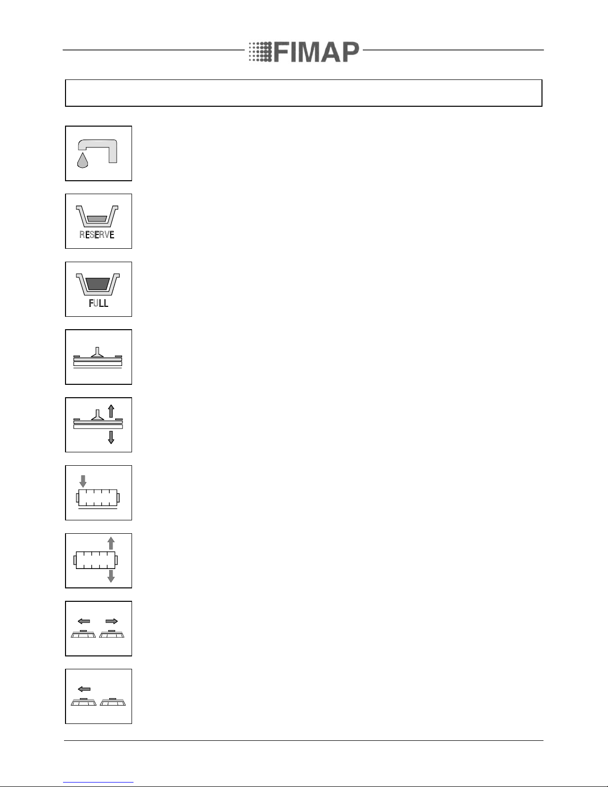
SYMBOLOGY USED ON THE MACHINE............................................................................................................................... 36
MACHINE PREPARATION...................................................................................................................................................39
1. HANDLING OF THE PACKED MACHINE......................................................................................................................................................... 39
2. HOW TO UNPACK THE MACHINE................................................................................................................................................................... 39
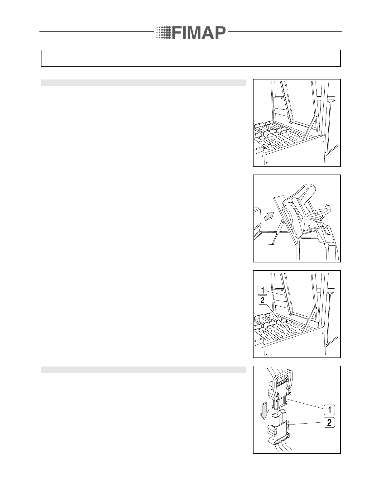
3. INSTALLATION OF THE BATTERIES INTO THE MACHINE.........................................................................................................................40
4. CONNECTION OF THE BATTERY CONNECTOR ............................................................................................................................................40
5. CONNECTION OF THE BATTERY CHARGER...................................................................................................................................................41
6. RECHARGE OF THE BATTERIES ......................................................................................................................................................................41
7. LEVEL INDICATOR FOR THE CHARGE OF THE BATTERIES........................................................................................................................41
8. SQUEEGEE ......................................................................................................................................................................................................... 42
9. ADJUSTMENT HEIGHT SQUEEGEE SUPPORT.............................................................................................................................................. 42
10. BRUSHES ASSEMBLY...................................................................................................................................................................................... 43
11. ASSEMBLY CYLINDRICAL BRUSH ................................................................................................................................................................. 44
12. ASSEMBLY SIDE BARS .................................................................................................................................................................................... 44
13. HOPPER............................................................................................................................................................................................................. 44
14. SOLUTION WATER .......................................................................................................................................................................................... 45
15. RECOVERY TANK............................................................................................................................................................................................. 45
GENERAL RULES OF SECURITY .........................................................................................................................................46
PERFORMANCE................................................................................................................................................................... 47
CHECK MOTORS..................................................................................................................................................................................................... 49
PRESSURE BRUSHES............................................................................................................................................................................................. 49
TRACTION ............................................................................................................................................................................................................... 50
SQUEEGEE AUTOMATIC - MANUAL.................................................................................................................................................................... 50
BASE CYLINDRICAL BRUSH (TUNNEL) AUTOMATIC - MANUAL.................................................................................................................... 50
BRAKES.....................................................................................................................................................................................................................51
HORN........................................................................................................................................................................................................................51
BLINKING AND WORKING LIGHTS......................................................................................................................................................................51
ON COMPLETION OF THE WORK ....................................................................................................................................... 52
DAILY MAINTENANCE........................................................................................................................................................ 54
CLEANING OF THE RECOVERY TANK................................................................................................................................................................. 54
CLEANING OF THE RECOVERY TANK FILTER................................................................................................................................................... 54
CLEANING OF THE SQUEEGEE............................................................................................................................................................................ 54
REPLACEMENT OF THE SQUEEGEE RUBBER....................................................................................................................................................55
DISASSEMBLY OF THE BRUSHES.........................................................................................................................................................................55
SOLUTION TANK AND FILTER CLEANING......................................................................................................................................................... 56
CLEANING OF THE HOPPER ................................................................................................................................................................................ 56
WEEKLY MAINTENANCE.................................................................................................................................................... 57
ADJUSTMENT SIDE BARS......................................................................................................................................................................................57
ADJUSTMENT SPLASH GUARD BRUSHES BASE ................................................................................................................................................57
ADJUSTMENT HEIGHT CYLINDRICAL BRUSH...................................................................................................................................................57
CLEANING OF THE SUCTION HOSE.................................................................................................................................................................... 58
CLEANING FILTER SUCTION MOTORS............................................................................................................................................................... 58
TROUBLE SHOOTING GUIDE.............................................................................................................................................. 59
INSUFFICIENT WATER ONTO THE BRUSHES ................................................................................................................................................... 59
THE SQUEEGEE DOES NOT DRY PERFECTLY.................................................................................................................................................... 59
THE SUCTION MOTOR DOES NOT FUNCTION ..................................................................................................................................................60
THE MACHINE DOES NOT START .......................................................................................................................................................................60
EXCESSIVE FOAM PRODUCTION ........................................................................................................................................................................60
THE MACHINE DOES NOT CLEAN SATISFACTORILY........................................................................................................................................61
CHOICE AND USE OF BRUSHES..........................................................................................................................................62
BATTERIES..........................................................................................................................................................................63
BATTERY TYPE ....................................................................................................................................................................................................... 63
MAINTENANCE OF THE BATTERY ...................................................................................................................................................................... 63
DISPOSAL OF BATTERIES..................................................................................................................................................................................... 63
34

On consignment of the machine
When the machine is consigned to the customer, an immediate check must
be performed to ensure all the material mentioned in the shipping
documents have been received and moreover to find out that the machine
has not suffered damage during transportation. If damage has occurred, get
the shipping agent to verify immediately the amount and nature of the
damage suffered and at the same time inform our claim department. It is
only by prompt action of this type that compensation for damage may be
successfully claimed.
Introductory comment
This is a sweep-scrubbing machine which, using the mechanic abrasive
action of four rotary brushes, the sweeping action of a cylindrical brush and
the chemical action of a solution water-detergent, is able to clean any type of
floor, picking up during its advance movement, the removed dirt and the
detergent solution which has not been absorbed from the floor. The
machine must be used only for such purpose. We would impress
upon you that any machine will function efficiently and operate successfully,
only if used correctly and maintained in fully efficient working order. We
therefore suggest you to read this instruction booklet carefully and re-read it
whenever difficulties arise in the course of machine use. Our Service
Department is at your disposal for all such advice and servicing as may prove
necessary.
TECHNICAL DATA
Magna 1300
Cleaning width mm
1300
Base side movement mm
100
Squeegee width mm
1460
Working capacity sqm/h
7800
Cylindrical brush ∅mm
300x1100
Cylindrical brush rpm rpm
580
Motor cylindrical brush V
36
Motor cylindrical brush W
750
Rotary brushes No. 4 ∅mm
345
Brushes rpm rpm
220
Brushes pressure kg
130÷180
Max. specific pressure grs/sqcm
66
Brushes motor V
36
Brushes motor W
1125
Traction motor V
36
Traction motor W
2000
Traction wheel ∅mm
350x130
Movement speed km/h
0÷6
Max. gradient under full load
10%
Suction motor No. 2 V
36
Suction motor No. 2 W
1200
Suction vacuum mbar
221
Rear elastic wheels ∅mm
370x110
Solution tank l
360
Recovery tank l
380
Steering diameter mm
3250
Machine length mm
2250
Machine height mm
1880
Machine width (without squeegee) mm
1340
Batteries V/Ah
36/640÷720
Batteries weight kg
780÷810
Machine weight (empty and without batteries) kg
840
Weight single brushes base kg
60
Acoustic pressure level Lpa dB (A)
70.8
Vibration level to the body m/s²
0.65
Vibration level to the hand m/s²
0.95
35

SYMBOLOGY USED ON THE MACHINE
Symbol denoting solenoid valve open
It is used to indicate the solenoid valve switch
It is used to indicate the signal lamp of the solenoid valve open
Symbol denoting solution tank empty
Symbol denoting recovery tank full
Symbol denoting squeegee all down
Symbol denoting up - down of the squeegee
It is used to indicate the signal lamp of the actuator when operating
Symbol denoting cylindrical brush all down
Symbol denoting up - down base of the cylindrical brush
It is used to indicate the signal lamp of the actuator when operating
Symbol denoting base side movement
It is used to indicate the signal lamp of the actuator when operating
Symbol denoting stop base side movement
The green signal lamp comes on when the brushes base is moved all to the left side
36

SYMBOLOGY USED ON THE MACHINE
Symbol denoting up - down of the brushes base
It is used to indicate the signal lamp of the brushes actuator when operating
Symbol denoting suction motor
It is used to indicate the suction motors switch
Symbol denoting cylindrical brush
It is used to indicate the switch of the cylindrical brush motor
Symbol denoting brushes
It is used to indicate the brushes motor switch
Symbol denoting charge level of the batteries
Symbol denoting brake
It is used to indicate the signal lamp of the hand brake on
It is used on top of the emergency brake lever
Symbol denoting oil tank brakes
It is used to indicate the signal lamp of oil shortness in the working brake system
Symbol denoting the switches of the blinking and working lights
Symbol denoting manipulator brushes
It is used on the instrument board to indicate the manipulator of the brushes base. Making
side movements with the manipulator, they correspond to side movements of the brushes
base. Longitudinal movements correspond to vertical movements of the brushes base.
37

SYMBOLOGY USED ON THE MACHINE
Symbol denoting manipulator cylindrical brush and squeegee
Making side movements with the manipulator, they correspond to vertical movements of the
squeegee. Longitudinal movements of the manipulator correspond to vertical movements of
the cylindrical brush base.
Symbol denoting pressure carried on the brushes
Symbol denoting regulation cock
3
2
1
Symbol denoting speed selector forwards and backwards
Symbol denoting control of the motors
38

MACHINE PREPARATION
1. HANDLING OF THE PACKED MACHINE
The machine is packed in a specific package provided on a pallet
for the handling with fork trucks. The packages cannot be placed
on top of each other.
The total weight is of 950 kg
The overall dimensions are:
Magna 1300
A: 1680mm
B: 1450mm
C: 2360mm
A
CB
2. HOW TO UNPACK THE MACHINE
1. Take off the outer package
2. The machine is fixed on the pallet with wooden wedges which
block the wheels
3. Take off these wedges
4. Using a chute, get the machine down from the pallet, pushing it
in reverse motion.
5. Keep the pallet for eventual transport necessities
39

MACHINE PREPARATION
3. INSTALLATION OF THE BATTERIES INTO THE MACHINE
The batteries are fitted in the appropriate compartment under the seat and
must be handled by using appropriate lifting equipment suitable both for the
weight and for the coupler system.
They must moreover satisfy the requirements quoted in the Specification CEI
21-5.
For maintenance and daily recharge of the batteries, it is necessary to follow
strictly all the indications given from the constructor or from his dealer .
All the installation and maintenance operations must be carried out by
specialized staff.
For the battery installation:
1. Lift the base support of the seat
2. Lift the battery cover (1 fig.3) and if necessary, take it off
3. Take off the left side panel (2 fig.3)
4. Put the batteries into its position according to the instructions indicated in
“BATTERIES”
5. Place the panel fixing in position again (2)
6. Lower the base support of the seat
7. Place the fixing of the battery cover in position again, if it has been taken
off (1)
4. CONNECTION OF THE BATTERY CONNECTOR
The battery connector (1) is placed in the left lower part of the operator and
must be connected to the connector (2) of the machine.
40

MACHINE PREPARATION
5. CONNECTION OF THE BATTERY CHARGER
The connector is placed in the left lower part of the operator seat.
The upper part (1), which is connected to the batteries, is the one
which has to be inserted to the connector (2) fixed to the cables of
the battery recharger. The coupling connector of the battery
charger is delivered in the bag where this instruction booklet is
found and must be assembled on the battery charger cables
following the suitable instructions (see instruction booklet of the
battery recharger).
6. RECHARGE OF THE BATTERIES
In order not to cause the risk of permanent damage to the
batteries, one should at all costs avoid their complete discharge
and effect recharging within a few minutes after that the signal
lamp of discharged batteries begins to blink.
NOTE: Never leave the batteries completely discharged, even if the
machine is not being used. When recharging the batteries,
keep the base support of the seat and the battery cover
lifted. Every 20 recharging operations, check the level of the
electrolyte and, if necessary, top up with distilled water.
7. LEVEL INDICATOR FOR THE CHARGE OF THE
BATTERIES
The batteries’ indicator is digital with 4 fixed positions and a
blinking one. The numbers which appear on the display show the
approximate charge level.
4= maximum charge, 3= charge 3/4, 2= charge 2/4, 1=
charge 1/4,
0= (blinking) discharged batteries
ATTENTION: Some seconds after that “0” blinks, the brushes
motors automatically switch off. Anyway, the machine can finish to
dry before recharging the batteries.
41

MACHINE PREPARATION
8. SQUEEGEE
The squeegee, which is packed separately from the machine, should be
assembled as shown in the figure, couple the screws (1) of the squeegee into
their seats on the squeegee support and fix them with a key CH17.
Fit the suction hose (2) into its coupling and fix it with the appropriate clamp.
During working operation, the rear rubber has to work slightly tilted
backwards and this equally in its whole length for about 5 mm.
If it is necessary to increase the rubber bending in the central part, then tilt
the squeegee body backwards, loosen the lock nut (2) and tighten the screw
(1). If the rubber bending is to be noticeable at the sides of the squeegee,
loosen the lock nut (2) and unscrew the screw (1). After regulations have been
done fix the lock nut. These operations have to be done with the help of a key
CH13.
9. ADJUSTMENT HEIGHT SQUEEGEE SUPPORT
The squeegee has to be regulated in height depending on the wearing of the
rubbers. To adjust this:
1. Loosen the ring nut (1)
2. With a key CH17 rotate the castor wheel through the nut (2) clockwise to
lift the squeegee and counterclockwise to lower it
3. Fix the ring nut (1)
NOTE: The right and left castor wheels have to be regulated equally.
42

MACHINE PREPARATION
10. BRUSHES ASSEMBLY
1. Connect the battery connector
2. Turn the key into position ON
3. With the manipulator lower the brushes base until it almost touches the
floor (do not lower completely)
4. Turn the key into position OFF and take it off from the instrument board
(to carry out the operations of brushes assembly with connected current
can cause damage to the hands).
5. Loosen the knobs (1) as shown in the figure
6. Extract the bases by sliding them
7. Lift the bases using suitable equipment both for their weight (60kg) as for
their coupling type (see the apposite labels)
8. With the brushes base in lifted position, insert the brushes into the seat of
the plate under the base until the three buttons fit into the holes of the
plate. Turn the brush so that the buttons are pushed towards their
retaining springs until the brush is clamped in place. The figure shows the
direction of rotation for the coupling of the right brush. The left brush has
to be rotated inversely.
9. Reassemble the bases on its support
10.Retighten the knobs
11. It is recommended to invert daily the position of the right brush with the
left one and vice versa. If the brushes are not new and they show deformed
bristles, it is better to reassemble them in the same position (the right to
the right side and the left to the left side), to avoid that the different
inclination of the bristles causes an overload to the brushes motor and
excessive vibrations.
43

MACHINE PREPARATION
11. ASSEMBLY CYLINDRICAL BRUSH
This operation must be carried out by a technician of the Fimap
service dept.
12. ASSEMBLY SIDE BARS
The side bars are already secured in the front part, but they must
be put into position in the rear part. Proceed as follows:
1. Insert the rear part of the side bar into the squeegee pin
2. Position the retaining clip
3. Repeat the same operations on both side bars
13. HOPPER
Check that the hopper is closed properly, otherwise push it until
the clamping of the closing hook (1) is obtained
44

MACHINE PREPARATION
14. SOLUTION WATER
Fill the solution tank with clean water at a temperature not more than 50°C
and add liquid detergent in the proper concentration following the
instructions of the manufacturer. Excess foam in the recovery tank could
damage the suction motors, so use only the minimum amount of detergent
necessary.
NOTE: Always use low foam detergent. To avoid the production of foam,
before starting to clean, put a minimum quantity of antifoam liquid into the
recovery tank. Never use pure acid.
15. RECOVERY TANK
Check that the inspection cover has been tightened,
and that the exhaust plug of the tank
and the plug of the exhaust pipe are closed
45

GENERAL RULES OF SECURITY
The rules below have to be followed carefully in order to avoid damages to the operator and to the
machine.
Read the labels carefully on the machine. Do not cover them for any reason and replace them immediately if
damaged
The machine must be used exclusively by authorized staff that has been instructed for its use
During the working of the machine, pay attention to other people and especially to the children
Do not mix different detergents, avoiding harmful odours
Do not place any liquid containers onto the machine
The storage temperature has to be between - 25°C and + 55°C
The perfect operating temperature should be between 0°C and 40°C
The machine can not be used or stored outside
The humidity should be between 30 and 95 %
Do not use the machine in explosive atmosphere
Do not use the machine as a means of transport
Do not use acid solutions which could damage the machine and/or the persons
Avoid working with the brushes when the machine stands still, in order to prevent floor damages
Do not vacuum inflammable liquids
Do not use the machine to collect dangerous powders
In case of fire, use a powder extinguisher. Do not use water
Do not strike shelvings or scaffoldings, where there is danger of falling objects
Adapt the utilization speed to the adhesion conditions
ATTENTION: Do not exceed over the limit gradient stated, to avoid conditions of instability
When the machine is in parking position, take off the key and insert the parking brake
The machine has to carry out simultaneously the operations of washing and drying. Different operations have to
be carried out in areas which are not permitted for the passage of non employed staff. Signal the areas of moist
floors with suitable signs
If the machine does not work properly, check by conducting simple maintenance procedures. Otherwise, it is
better to ask for FIMAP technical service.
Use only original FIMAP brushes indicated in the paragraph “CHOICE AND USE OF BRUSHES”
Where parts are required, ask for ORIGINAL spare parts to an agent and/or to an authorized dealer.
In case of danger act immediately upon the emergency lever (connector placed on the left side of the operator)
For any cleaning ad maintenance operation take off the power supply from the machine
Do not take off the pieces which require the use of tools to be removed
Do not wash the machine with direct water jets or with high water pressure nor with corrosive material
Every 200 working hours have a machine check through a Fimap service department
Before using the machine, check that all doors and coverings are in their position as indicated in this use and
maintenance catalogue
The machine should not be abandoned, because of the presence of toxic-harmful materials (batteries, oil etc.).
This disposal must be subject to the rules which provide for its scrapping in appropriate centres
In order to avoid scales on the solution tank filter, do not fill the detergent solution many hours before the
machines’ use
46

PERFORMANCE
1. Carry out the operations for the preparation of the machine
2. Sit on the driver’s seat
3. Check that the parking brake is released (1)
4. Connect the connector to the batteries (2)
5. Turn the key of the general switch (3) clockwise of a quarter turn.
Immediately, the red signal lamps (4) on the instrument board begin to
blink and the batteries’ display (5) comes on. The blinking indicates that
the checking of the motors is taking place
6. Press the suction motors switch (1)
7. Press the switch of the cylindrical brush motor (2)
8. Press the solenoid valve switch (3)
9. Press the brushes motor switch (4)
10.Place the switches (1 and 2) into their automatic positions
11. Open the cock rotating the knob (3) counterclockwise. The signal lamp of
the water (4) comes on only during the moving period
12.Collocate forward the drive selector (1)
13.Select the speed movement rotating the knob (2)
47

PERFORMANCE
14.Push forward the brushes manipulator (1) so to lower the base. During the
descent, the signal lamp of the actuator and the brushes motor come on.
The brushes base will be in its working position when the yellow signal
lamp (2) comes off
15. Press the accelerator pedal. The machine begins to move, the squeegee and
the tunnel begin to lower themselves and the suction motors come on.
During the first metres of operating, check that the brushes pressure is
suitable (see further on under “BRUSHES PRESSURE”), that the quantity
of the detergent solution is sufficient and that the squeegee dries perfectly.
The machine will now start working efficiently until the detergent solution
runs out.
Immediately disconnect the emergency lever (1) situated on the left
side from the operator and apply the emergency brake (2),
whenever the machine develops operating problems when it is
working. These commands disconnect all the functions on the machine. To
start the machine again, once the problem has been solved, turn off the key
(3), reconnect the connector (1), switch on the key (3) and lower the parking
brake lever (2).
The machine will not start if the operator is not properly seated.
When the solution tank is empty, the signal lamp (1) on the instrument board
comes on.
When the recovery tank is full, the signal lamp (2) comes on and the suction
motors stop. To start them up again, even if the tank has been emptied, it is
necessary to first turn off the main switch key (3) and then on again.
48

PERFORMANCE
CHECK MOTORS
This machine is equipped with a system of amperometric control of
the motors. The symbol shown in the figure wants to simulate the
machine seen from the top and the blinking of each single led
visualizes a specific problem:
Led 1 indicates the traction motor
Led 2 indicate the brushes motors
Led 3 indicates the cylindrical brush motor
Led 4 indicate the suction motors
When preset overload limits of a motor are reached, the
corresponding red signal lamp starts to blink. After a few seconds
the motor stops and the signal lamp of the relative switch goes off.
To start up the motor again, turn the main switch key off and on
again. If the motor stops again, check the reason of the overload to
prevent motor damage. Generally, for the brushes motors it is
enough to reduce their brushes pressure (see “PRESSURE
BRUSHES” and “ADJUSTMENT HEIGHT CYLINDRICAL
BRUSH”).
For problems on other motors it is necessary to seek for Fimap
technical service.
PRESSURE BRUSHES
It is possible to adjust the brushes pressure using the hand wheel
(1) placed on the left side of the operator. To increase the pressure
rotate clockwise. The pressure gauge (2) moves up as pressure
increases.
The pressure must be chosen based on the type of floor and the
type of dirt. Excessive pressure causes higher brushes wear and a
major energy consumption (for further information read on
“CHOICE AND USE OF BRUSHES”)
49

PERFORMANCE
TRACTION
These machines are equipped with electronically commanded traction, with
three speeds forwards and one backwards. To move the machine, it is
necessary to turn the key and then move forwards (forward movement) or
backwards (rear movement) the manipulator (1). Press the drive pedal and the
machine will start to move. The movement speed can be adjusted rotating the
selector (2).
NOTE : During reverse motion, if the switches (1 and 2) automatic-manual of
the squeegee and the tunnel are on manual position, remember to lift the
squeegee and the tunnel through the manipulator (3). During transfer, put the
switches (1 and 2) onto manual.
SQUEEGEE AUTOMATIC - MANUAL
Automatic : If the switch is placed on automatic, lowering of the squeegee
and starting of the suction motors are obtained with the machine
advancement. Also, lifting of the squeegee and stopping of the suction motors
are achieved with the reverse motion of the machine.
Manual : If the switch is placed on manual, the squeegee lifts and lowers
itself manually through the manipulator (2). The operation of the suction
motors is commanded anyhow through the squeegee movement.
BASE CYLINDRICAL BRUSH (TUNNEL) AUTOMATIC - MANUAL
Automatic : If the switch is placed on automatic, lowering of the tunnel and
starting of the cylindrical brush motor are obtained with the machine
advancement. Also, lifting of the tunnel and stopping of the motor are
achieved with the reverse motion of the machine.
Manual : If the switch is placed on manual, the tunnel lifts and lowers itself
manually through the manipulator (2). The operation of the motor is
commanded anyhow through the tunnel movement
50

PERFORMANCE
BRAKES
To brake, press with the left foot the pedal of the service brake (2).
In case of bad operation of this b
r
ake, or in case of necessity
(interruption, danger), act upon the parking brake (1).
HORN
The machine is equipped with a horn switch. To operate it, press
the push button as shown in the figure.
BLINKING AND WORKING LIGHTS
The machine is equipped with a blinking light, a rear working light
and two front working lights. For their lighting press the switches
as shown in the figure.
51

ON COMPLETION OF THE WORK
Having finished the job and before any type of maintenance is done:
1. Close the cock
2. Raise the base of the brushes
3. Switch off the brushes motor switch
4. Switch off the solenoid valve switch
5. Switch off the switch of the cylindrical brush motor
6. Switch off the suction motors switch
7. Place the squeegee switch onto manual
8. Lift the squeegee
9. Place the switch of the tunnel onto manual
10.Lift the tunnel
11. Bring the machine up to the place provided for the water outlet
12.Turn the key 1/4 round counterclockwise
13.Take off the exhaust pipe from its hook, unscrew the exhaust plug and
empty the recovery tank. This operation has to be carried out using gloves
to protect from contact with dangerous solutions
52
Table of contents
Other Fimap Floor Machine manuals

Fimap
Fimap BMg Sanitizer User manual

Fimap
Fimap GENIE E User manual

Fimap
Fimap GAMMA 66 User manual

Fimap
Fimap IMx Instruction manual

Fimap
Fimap FM43 ORBITALE User manual

Fimap
Fimap MMg base Installation instructions

Fimap
Fimap FM43 ORB User manual

Fimap
Fimap FS700 H User manual

Fimap
Fimap Mx Series User manual

Fimap
Fimap FM33 User manual
Popular Floor Machine manuals by other brands

MK Diamond Products
MK Diamond Products MK-VTS/50 Owner's manual operating instruction & parts list

Clarke
Clarke Clean Track 12 manual

Kärcher
Kärcher B 60/10 C Original instructions

Tennant
Tennant T7 Operator's manual

Numatic
Numatic TwinTec 455 Operation manual

CONQUEST
CONQUEST Carbon Edge 28TE Operator's manual