Fimco 200-3PT-BL User manual

Page 1
OWNER’S MANUAL
Model: 200-3PT-BL
(5303085)
(200 Gallon 3-Point Sprayer
w/Boom-Buster ’Boomless’ Boom Assembly
& Handgun, Pump, Coupler & Agitator)
www.fimcoindustries.com
1000 FIMCO Lane, P.O. Box 1700, North Sioux City, SD 57049
Toll Free Phone: 800-831-0027 : Toll Free Fax: 800-494-0440
[5195388 (09/20)]
BEFORE RETURNING THIS PRODUCT
FOR ANY REASON, PLEASE CALL
1-800-831-0027
MONDAY-FRIDAY, 8:00 AM TO 5:00 PM CST
If you should have a question or experience a problem with
your Fimco Industries Product: Visit our website @
www.fimcoindustries.com or call the Toll free number above. Our
technical support representatives will be happy to help you.
In most cases a customer service rep. can resolve
the problem over the phone.
To obtain prompt, efficient service, always remember to give the
following information....
• Correct Part Description and/or part number
• Model number and Serial Number
Part descriptions and numbers can be obtained from the
illustrated parts list section(s) of this manual.
General Information
Thank you for purchasing this product. The purpose of this
manual is to assist you in operating and maintaining your
3 Point sprayer.
Retain a copy of your receipt for your unit, as it will be required
to validate any warranty service.
Warranted against manufacturer or workmanship defects from
date of purchase with copy of receipt:
Homeowner Usage: One Year
Commercial Usage: 90 Days.
Assembly Instructions
1. Install the preassembled tee valve sub-assembly to the 3-point
carrier valve mount and position as shown.
2. Slide a hose clamp on to the
bypass hose (from the relief
valve), then with a twisting
motion, slip the bypass hose
over the fitting on the top of
the tank. Slide the hose clamp
to the end of the hose and
secure.
Category I or II

Page 2
3. fitting into the strainer. Find the 1” x 36” pump feeder hose. Slip
a hose clamp onto the ends of the hose. With a twisting motion,
slip the hose all the way onto the fitting and secure with the
hose clamp.
4. Using a good quality thread sealant, thread the 1” fitting into the
inlet (IN) side of the pump and the 3/4” fitting to the outlet (OUT)
side of the pump. With a twisting motion, attach the other end of
the 1” hose to the 1” fitting on the inlet to the pump. Slip a 3/4”
hose clamp onto the 3/4” hose coming off the valve assembly
and with a twisting motion, attach the 3/4” hose to the output
side of the pump and securing with the hose clamp.
5. The roller pump IS included with the assembly. Attach the
adapter, the torque chain and S-hook to the pump as needed. It
is intended for your pump to be mounted directly to the tractor
PTO. The torque chain needs to be secured to the tractor to
keep your pump from spinning.
6. Wrap the handgun hose around the hose hangers which are
attached to the tank straps.
7. Using sealant thread the gauge into the top of the tee valve
assembly.
Inlet to Pump
Outlet to Valve
1”
3/4”
Hose Hangers

Page 3
Boom Assembly Instructions
1. Attach the boom buster bracket to the telescoping brackets,
using the two square u-bolts and 4 whiz nuts. The telescoping
brackets are already mounted to the 3-point frame.
2. Slide the boom buster subassembly onto the boom buster
bracket. Set the desired height and lock in place with the
handle screw.
3. Slip the two 1/2” hose clamps on to the feeder hoses coming
from the valve assembly. With a twisting motion, slide the feed-
er hoses all the way on to the hose barbs and secure with hose
clamps.
4. Thread the QJ Diaphragm Check Valve 1/4 MNPT into the
reducer bushing on the elbow.
5. Insert the blue (50 mesh) nozzle check valve strainer.
6. Attach the extended range tip and lock in place.
7. Repeat for other side.
Your Sprayer is now ready to use.

Page 4
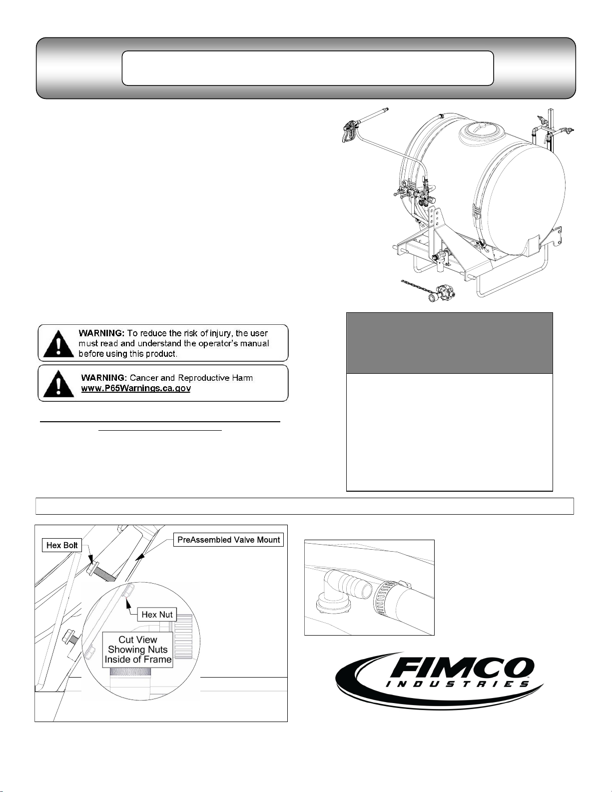
Information About the Sprayer
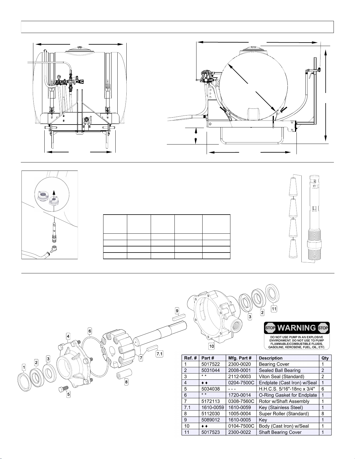
Roller pumps are positive displacement pumps, which means that
the entire solution being pumped must go somewhere or the pump
will break. In this roller pumping system, solution is drawn from the
tank and forced to a planned source, such as boom nozzles or hand-
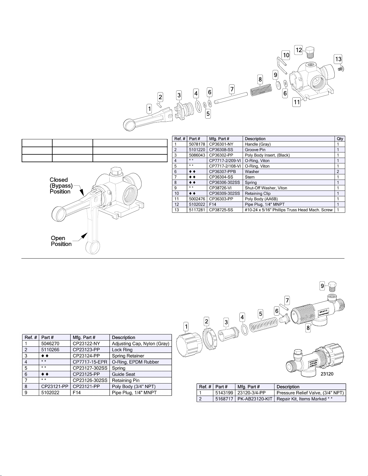
gun. The pressure is controlled by a pressure relief valve, which is a
spring-loaded device that controls the amount of fluid bypassed
(recirculated) to the tank. The gray handle is to be tightened to in-
crease pressure and loosened to decrease pressure.
The ‘directo-valve’ is the on/off control which allows the operator to
manually control the solution going to the boom.
IMPORTANT: Remove tank lid and be sure the tank is
clean and free of any foreign material. Rinse tank out of any
tank residue before filling with water to test.
Testing the Sprayer
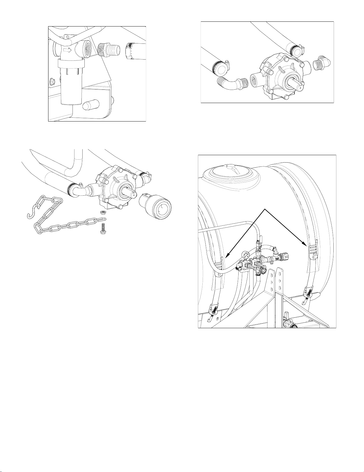
Attach the sprayer to the tractor 3 point hitch. Mount the pump to the
PTO and affix the torque chain.
NOTE: It is important for to test your sprayer with plain water before
actual spraying is attempted. This will enable you to familiarize
yourself and check for leaks without the possibility of losing any
expensive chemicals.
Fill the tank about 1/2 full with plain water.
Before starting, open the suction line valve (located underneath the
carrier frame), turn the relief valve handle out to lower the line
pressure. This will help prime the pump.
CAUTION: Always be sure that the water (or solution) has reached
the pump before starting your sprayer. If the pump is allowed to run
dry, serious damage to the pump will result.
Always have the pressure line open to the tips so that the air which
may be trapped in the line will be forced (or purged) out.
Start the tractor PTO. Check the entire system for leaks. Once the
pump is primed, the pressure may be increased by turning the han-
dle of the pressure relief valve in. Keep the pressure line open to the
tips when setting the pressure. Set the pressure and then lock the
relief valve handle in place. Shut off the directo-valve and check for
leaks again. Pressure will increase when the pressure line valve is
closed and then return to the preset pressure when the valve is
opened again.
During the testing period, be sure to observe the spray pattern given
by the spray nozzles. If there is any pattern distortion, it will be
necessary to remove and clean the affected tips.
Caution: Never use a metal object or other sharp item for cleaning a
nozzle tip. It is better to use a nozzle brush (NOT wire brush) or
compressed air for tip cleaning.
Conditions of weather and terrain must be considered when setting
the sprayer. Do not spray on windy days. Protective clothing must be
worn in some cases
Be sure to read the chemical label(s) before application!
Operation
The performance of any agricultural chemical depends upon the
proper application.
Always fill the tank with a desired amount of water first and then add
the chemical slowly, mixing as you pour the chemical into the tank.
You may use the handgun to spraying into the solution in order to
mix the chemical and water.
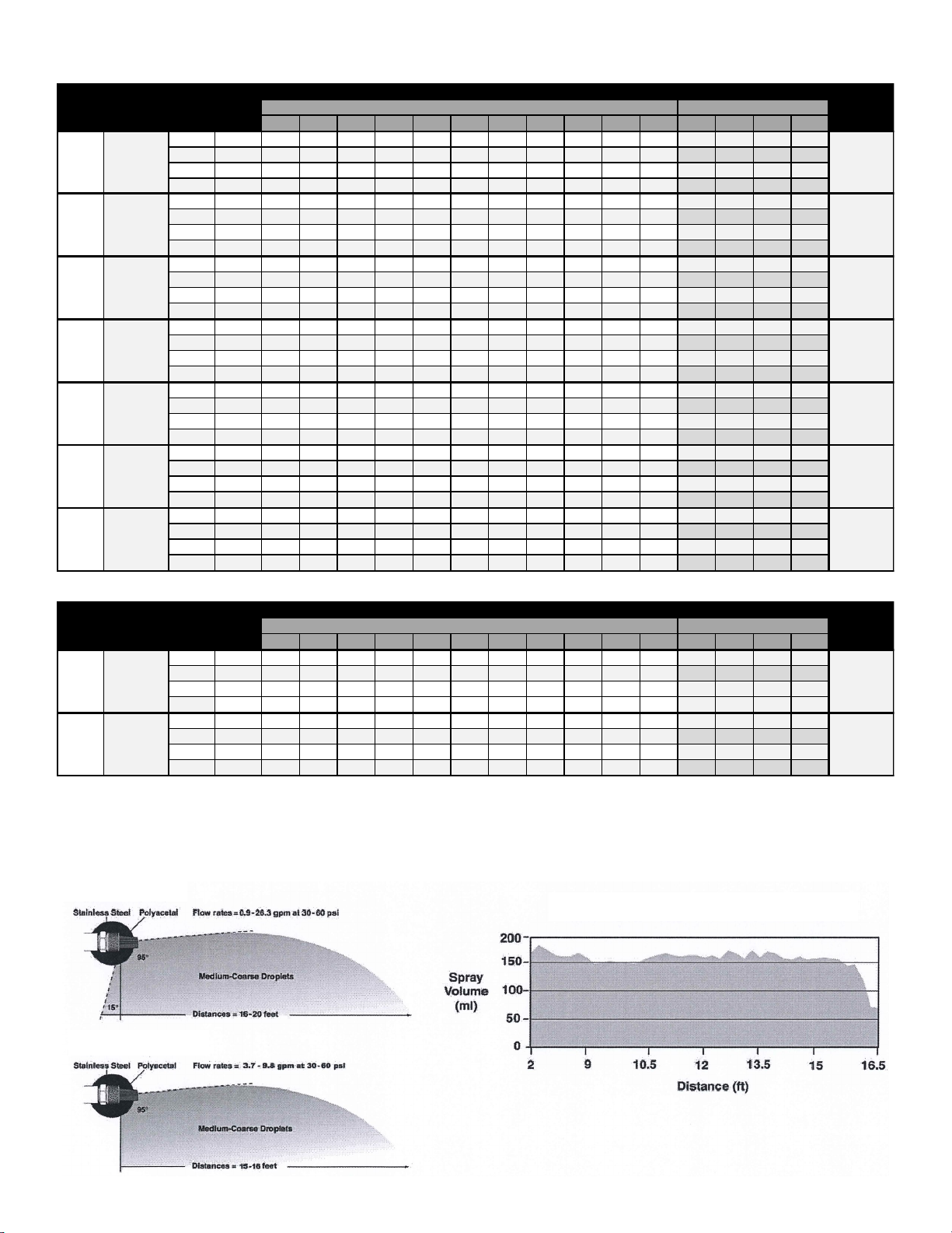
The speed and pressure charts shown indicate the rates can be
changed considerably by changing speed and pressure. The pump-
ing system draws solution from the tank through the strainer/filter and
to the pump. The pump forces the solution under pressure to the
boom nozzles.
Rotating the adjustable nozzle tip on the handgun will change
the tip pattern from a straight stream to a cone pattern (fine
mist)
Calibration
Chemical labels may show application rates in gallons per acre, gal-
lons per 1000 square feet or gallons per 100 square feet. You will
note that the tip chart shows 2 of these rating systems. Once you
know how much you are going to spray, then determine (from the tip
chart) the spraying pressure (PSI), and the spraying speed (MPH).
Determining the proper speed of the pulling vehicle can be done by
marking off 100, 200 & 300 feet. The speed chart indicates the num-
ber of seconds it takes to travel the distances. Set the throttle and
with a running start, travel the distances. Adjust the throttle until you
travel the distances in the number of seconds indicated by the speed
chart. Once you have reached the throttle setting needed, mark the
throttle location so you can stop and go again, returning to the same
speed.
Add water and proper amount of chemical to the tank and drive to the
starting place for spraying.
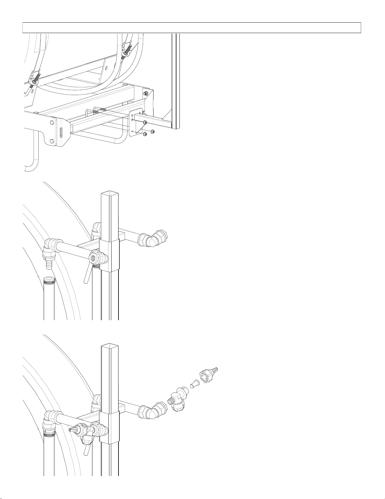
Using the Boom Nozzles
Four things must be considered before spraying with the boom.
How much chemical must be mixed in the tank.
Rate of spray (gallons per acre to be sprayed).
What pressure (p.s.i.) will be used.
Speed traveled (mph) while spraying.
Refer to the chemical label to determine your chemical mixture
See the tip chart to determine the pressure to be used. The
chart will also show the speed used when spraying.
Start the pump and open the valve to the boom nozzles.
Check the spray pattern. Usually you can see the coverage
better on a solid concrete surface, such as a driveway.
Spraying Solutions Other Than Water
Since all the tabulations are based on spraying water, which weighs
8.34 lbs. per USA gallon, conversion factors must be used when
spraying solutions which are heavier or lighter than water. To deter-
mine the proper size nozzle for the solution to be sprayed, first multi-
ply the desired GPM or GPA of solution by the rate conversion factor.
Then use the new converted GPM or GPA rate to select the proper
size nozzle.
Example: Desired application rate is 20 GPA of 28% Nitrogen.
Determine the correct nozzle size as follows:
GPA (Solution) x Conversion Factor = GPA
20 GPA (28%) x 1.13 + 22.6 GPA (Water)
The applicator should choose a nozzle size that will supply 22.6 GPA
of water at the desired pressure.
Speed in M.P.H.
(Miles Per Hour)
100 Ft. 200 Ft. 300 Ft.
1.0 68 sec. 136 205
2.0 34 68 102
3.0 23 45 68
4.0 17 34 51
5.0 14 27 41
6.0 11 23 34
7.0 9.7 19 29
8.0 8.5 17 26
9.0 7.6 15 23
10.0 6.8 14 20
Speed Chart
Time Required in seconds to travel a distance of
Weight of Solution
Specific
Gravity
Conversion
Factors
7.0 lbs. per gallon .84 .92
8.0 lbs. per gallon .96 .98
8.345 lbs. per gallon
(Water) 1.00 1.00
9.0 lbs. per gallon 1.08 1.04
10.0 lbs. per gallon 1.20 1.10
10.66 lbs. per gallon
(28% Nitrogen)
1.28 1.13
11.0 lbs. per gallon 1.32 1.15
12.0 lbs. per gallon 1.44 1.20
14.0 lbs. per gallon 1.68 1.30

Page 5
Thread XT Model PSI GPM 4567810 12 14 16 18 20 2345
30 0.9 7.0 5.6 4.6 4.0 3.5 2.8 2.3 2.0 1.7 1.5 1.4 0.32 0.21 0.16 0.13
40 1.0 7.7 6.2 5.2 4.4 3.9 3.1 2.6 2.2 1.9 1.7 1.5 0.36 0.24 0.18 0.14
50 1.1 8.8 6.8 5.7 4.9 4.3 3.4 2.8 2.4 2.1 1.9 1.7 0.39 0.26 0.20 0.16
60 1.2 9.3 7.4 6.2 5.3 4.6 3.7 3.1 2.7 2.3 2.1 1.9 0.43 0.28 0.21 0.17
30 1.7 12.4 9.9 8.3 7.1 6.2 5.0 4.1 3.5 3.1 2.8 2.5 0.57 0.38 0.28 0.23
40 2.0 14.6 11.6 9.7 8.3 7.3 5.8 4.9 4.2 3.6 3.2 2.9 0.67 0.45 0.33 0.27
50 2.2 16.0 12.8 10.7 9.2 8.0 6.4 5.3 4.6 4.0 3.6 3.2 0.74 0.49 0.37 0.29
60 2.4 17.5 14.0 11.6 10.0 8.7 7.0 5.8 5.0 4.4 3.9 3.5 0.80 0.53 0.40 0.32
30 2.1 14.3 11.4 9.5 8.2 7.1 5.7 4.8 4.1 3.6 3.2 2.9 0.65 0.44 0.33 0.26
40 2.4 16.5 13.2 11.0 9.4 8.3 6.6 5.5 4.7 4.1 3.7 3.3 0.76 0.50 0.38 0.30
50 2.7 18.0 14.8 12.3 10.5 9.2 7.4 6.1 5.3 4.6 4.1 3.7 0.84 0.56 0.42 0.34
60 2.9 20.0 16.2 13.5 11.5 10.1 8.1 6.7 5.8 5.1 4.5 4.0 1.0 0.65 0.49 0.39
30 3.7 25.0 20.0 17.0 14.5 12.7 10.2 8.5 7.3 6.4 5.7 5.1 1.2 0.78 0.58 0.47
40 4.3 30.0 24.0 19.7 16.9 14.8 11.8 9.9 8.4 7.4 6.6 5.9 1.4 0.90 0.68 0.54
50 4.8 33.0 26.0 22.0 18.9 16.5 13.2 11.0 9.4 8.3 7.3 6.6 1.5 1.0 0.76 0.61
60 5.3 36.0 29.0 24.0 21.0 18.2 14.6 12.1 10.4 9.1 8.1 7.3 1.7 1.1 0.84 0.67
30 6.9 50.0 40.0 33.0 29.0 25.0 20.0 16.7 14.4 12.6 11.2 10.0 2.3 1.5 1.2 0.92
40 8.0 58.0 47.0 39.0 33.0 29.0 23.0 19.4 16.6 14.6 12.9 11.6 2.7 1.8 1.3 1.1
50 8.9 65.0 52.0 43.0 37.0 32.0 26.0 22.0 18.5 16.2 14.4 13.0 3.0 2.0 1.5 1.2
60 9.8 71.0 57.0 48.0 41.0 36.0 29.0 24.0 20.0 17.8 15.9 14.3 3.3 2.2 1.6 1.3
30 14.5 112.0 90.0 75.0 64.0 56.0 45.0 37.0 32.0 28.0 25.0 22.0 5.1 3.4 2.6 2.1
40 16.7 129.0 103.0 86.0 74.0 65.0 52.0 43.0 37.0 32.0 29.0 26.0 5.9 4.0 3.0 2.4
50 18.7 145.0 116.0 96.0 83.0 72.0 58.0 48.0 41.0 36.0 32.0 29.0 6.6 4.4 3.3 2.7
60 20.5 159.0 127.0 106.0 91.0 79.0 63.0 53.0 45.0 40.0 35.0 32.0 7.3 4.9 3.6 2.9
30 18.6 115.0 92.0 77.0 66.0 58.0 46.0 38.0 33.0 29.0 26.0 23.0 5.3 3.5 2.6 2.1
40 21.5 133.0 106.0 89.0 76.0 67.0 53.0 44.0 38.0 33.0 30.0 27.0 6.1 4.1 3.1 2.4
50 24.0 149.0 119.0 99.0 85.0 74.0 59.0 50.0 42.0 37.0 33.0 30.0 6.8 4.5 3.4 2.7
60 26.3 163.0 130.0 108.0 93.0 81.0 65.0 54.0 46.0 41.0 36.0 33.0 7.5 5.0 3.7 3.0
Thread XT Model PSI GPM 4567810 12 14 16 18 20 2345
30 3.7 29.0 23.0 19.1 16.4 14.3 11.4 9.5 8.2 7.2 6.4 5.7 1.3 0.88 0.66 0.53
40 4.3 33.0 27.0 22.0 19.0 16.6 13.3 11.1 9.5 8.3 7.4 6.7 1.5 1.0 0.76 0.61
50 4.8 37.0 30.0 25.0 21.0 18.6 14.9 12.4 10.6 9.3 8.3 7.4 1.7 1.1 0.85 0.68
60 5.3 41.0 33.0 27.0 23.0 20.0 16.4 13.7 11.7 10.2 9.1 8.2 1.9 1.3 0.94 0.75
30 6.9 50.0 40.0 33.0 29.0 25.0 20.0 16.7 14.4 12.6 11.2 10.0 2.3 1.5 1.2 0.92
40 8.0 58.0 47.0 39.0 33.0 29.0 23.0 19.0 16.6 14.6 12.9 11.6 2.7 1.8 1.3 1.1
50 8.9 65.0 52.0 43.0 37.0 32.0 26.0 22.0 19.0 16.2 14.4 13.0 3.0 2.0 1.5 1.2
60 9.8 71.0 57.0 48.0 41.0 36.0 29.0 24.0 20.0 18.0 15.9 14.3 3.3 2.2 1.6 1.3
3/8"
MNPT
XT043R
BLUE
1/2"
MNPT
XT080R
YELLOW
Swath
Width (Ft)
@ 40 PSI
16
17
18
18
17
16
20
Swath
Width (Ft)
@ 40 PSI
16
15
RIGHT-OF-WAY APPLICATIONS
Gallons per Acre
GAL/1000 Sq. Ft.
MPH
MPH
1/2"
MNPT
XT080
RED
3/4"
MNPT
XT167
WHITE
3/4"
MNPT
XT215
GRAY
1/4"
MNPT
XT020
FC-XT020
BLUE
1/4"
MNPT
XT024
FC-XT024
YELLOW
3/8"
MNPT
XT043
FC-XT043
ORANGE
BROADCAST & TURF APPLICATIONS
1/4"
MNPT
XT010
GREEN
Gallons per Acre
GAL/1000 Sq. Ft.
MPH
MPH
Boomless spray nozzles are great for rough terrains, road side spraying, fence rows and other areas that are difficult to apply with a traditional boom.
Note: Application rates are based on overall swath widths listed at 48” height. Refer to operating instructins if using a different swath.
Standard Pattern
Right-of-Way Pattern
Typical Spray Pattern Produced by XT Series

Page 6
A torque chain, ‘S’ hook, nut and bolt are included in this assembly to
secure your pump during operation.
1. Attach one end of the torque chain over the threaded stem of the
bolt
2. Thread the whiz nut onto the bolt. Hand-tighten
3. Thread the bolt, chain and nut ‘pre-assembly’ into the threaded
hole on the underside of the pump. Tighten sufficiently
4. Affix the ‘S’ Hook to your frame (or hitch). Wrap the chain around
the frame or hitch and ‘S-Hook’ it in place. Make sure this con-
nection is very secure! Not having a good, tight connection may
result in the pump spinning on your PTO shaft and damaging
some components of your sprayer
*** Insure that this connection point will not allow the roller pump to
spin on the PTO shaft ***
Torque Chain Attachment to a Roller Pump
Strap/Buckle Detail
Strap Attachment
to a “Bent” Buckle
The nylon straps are to be inserted in and out of the slots in the
buckle, as shown. Be sure the straps are snug before tightening the
hook bolts. In most cases, it will be necessary to re-tighten the straps
after filling the tank with liquid.
Miscellaneous Conversion Factors
One Acre = 43,560 square feet = 0.405 Hectare
One Hectare = 2.471 Acres
One Gallon Per Acre = 9.35 Liters Per Hectare
One Mile = 5,280 Feet = 1,610 Meters = 1.61 Kilometers
One Gallon = 128 Fluid Ounces = 8 Pints = 4 Quarts = 3.79 Liters =
0.83 Imperial Gallons
One Pound Per Square Inch = 0.069 bar. = 6.895 Kilopascals
One Mile Per Hour = 1.609 Kilometers Per Hour
Higher pressure not only increases the flow rate of the nozzle, but it
also influences the droplet size and the rate of orifice wear. As pres-
sure is increased, the droplet size decreases and the rate of orifice
wear is increased.
The values given in the tabulation section of this your owners manual
indicates the most commonly used pressure ranges for the
associated spray tips.
Tank Care & Maintenance
Warning: Do not use the tank as a container for fuel oils, kerosene,
gasoline or any other petroleum distillate product. All polyolefins are
softened and permeated by such products. In an enclosed area the
vaporization of these materials from the outside surface of the tank
could create a dangerous condition.
The tank should not be used as a pressure vessel nor used with
chemicals or solutions having a weight of more than 12 pounds per
gallon.
Store the tank in a dry dark place when not in use. Storage out of
sunlight will prolong the life of the tank.
Do not drop, strike or kick the tank, especially at low temperatures.
Tanks become brittle and are subject to cracking at temperatures
below 20° Fahrenheit.
Always flush the tank with water and a neutralizing agent (such as
‘Nutra-Sol’) at the end of each use, to prevent contamination of solu-
tions.
Maintenance During/After Spraying
Periodically close the suction line valve and check the strainer and
clean the screen.
Proper care and maintenance will prolong the life of your sprayer.
After use, fill the sprayer tank part way with water. Start the sprayer
and allow the clear water to be pumped through the plumbing system
and out through the spray nozzles. Refill the tank about half full with
plain water and use FIMCO Tank Neutralizer and Cleaner and repeat
cleaning instructions above (If no tank cleaner is available, you may
substitute dish soap for this step, about 1-2 oz. per gallon). Flush the
entire sprayer with the neutralizing/cleaning agent, then flush out one
more time with plain water. Follow the chemical manufacturer’s dis-
posal instructions of all wash or rinsing water. For the boom (if appli-
cable) remove the tips and screens from the nozzle assemblies.
Wash these items out thoroughly. Blow the orifice clean and dry. If
the orifice remains clogged, clean it with a fine bristle (NOT WIRE)
brush or with a toothpick. Do not damage the orifice. Water rinse and
dry the tips before storing.
WARNING: Some chemicals will damage the pump valves if
allowed to soak untreated for a length of time! ALWAYS flush the
pump as instructed after each use. DO NOT allow chemicals to sit in
the pump for extended times of idleness. Follow the chemical manu-
facturer’s instructions on disposal of all waste water from the sprayer.
Winter Storage
Drain all water out of your sprayer, paying special attention to the
pump, handgun and valve(s). These items are especially prone to
damage from chemicals and freezing weather.
The sprayer should be winterized before storage by pumping a solu-
tion of automotive antifreeze (containing a rust inhibitor) through the
entire plumbing system. This antifreeze solution should remain in the
plumbing system during the winter months. When spring time comes
and you are preparing your sprayer for the spray season, rinse the
entire plumbing system out, clearing the lines of the antifreeze solu-
tion. Proper care and maintenance will prolong the life of your
sprayer.
Available ONLY in
complete assembly

Page 7
‘Directo Valve’ - Manually Operated Control Valve
Corrosion Resistant Materials: Wetted Parts Polypropylene, 316SS and Polyethylene
Maximum Pressure = 150 p.s.i.
Large Capacity - 12.5 G.P.M. @ 5 p.s.i. Pressure Drop
3/4” NPT (F) Inlet Connection
1/2” NPT (F) Spray Line Connection
3/4” NPT (F) Continuous By-Pass Connection
Valves may be connected w/close nipples for multiple section spray control
Fimco # Mfg. Part #
5143316 AA6B
5168718 PK-AB6B-KIT
Description
Directo-Valve (AA6B)
Repair Kit, Items Marked * *
Piston Type Pressure Relief/Regulating Valves
Bypasses excess fluid. Adjustable to maintain control of line pressure at any pressure within the valve operating range.
Selected pressure setting firmly held in place by locknut. Extra large passages to handle large flows.
Polypropylene with stainless steel spring
Excellent chemical resistance
EPDM O-Rings
Fore pressure to 150 p.s.i.
1/4” port for pressure gauge
3/4” NPT (M) inlet & (F) outlet connections
* * Available ONLY in Repair Kit
♦ ♦ ONLY Available in Complete Assembly
* * Available ONLY in Repair Kit
♦ ♦ ONLY Available in Complete Assembly

Page 8
Detail A Detail B
Detail C
See Detail C
See Detail B
IN to Pump
See Detail A
Exploded View:
200-3PT-BL
(5303085)
Refer to the parts list
next page for part numbers.
OUT to Valves

Page 9
Parts List: 200-3PT-BL (5303085)
Hose to RH BoomBuster Hose to LH BoomBuster
Hose to Valve
from Pump
Handgun Hose
Hose to
Agitator
Hose to
Bypass Plumbing Detail
* *: Available ONLY in complete assembly

Page 10
Cast Iron 8-Roller Pump Assembly
#5271077 (Hypro Mfg. Part # 7560C)
* * = Available ONLY in Repair
Parts Kit #7771794 (3430-0381)
Consists of Rollers, O-Ring &
Viton Seals
♦ ♦ Available ONLY in Complete
Assembly
Dimensions
50.000”
37.500”
68.813”
47.500”
9.500”
54.438”
38.000”
Black
1/8” Orifice
Red
5/32” Orifice
Blue
3/16” Orifice
White
1/4” Orifice
Color Coded Nozzle Inserts
Operation
As solution is forced through the agitator, the venturi action
triples the flow through the agitator.
The valve in the line may shut off the agitation completely
when not needed or it can throttle the amount of solution
going to the agitator if too much agitation occurs.
Orifice
Color
Orifice P.S.I.
Inlet Flow
(G.P.M.)
Outlet Flow
(G.P.M.)
Black 1/8" 30 2.9 9.5
Red 5/32" 30 4.1 13.2
Blue 3/16" 30 5.3 15.4
White 1/4" 30 6.5 19.5

Page 11
1. Use a pressure relief device on the discharge side of the
pump to prevent damage from pressure buildup when the
pump discharge is blocked or otherwise closed and the pow-
er source is still running.
2. WARNING: Never pump flammable or explosive fluids such
as gasoline, fuel oil, kerosene, etc. Never use in explosive
atmospheres. The pump should be used only with liquids
compatible with the pump component materials. Failure to
follow this warning can result in personal injury and/or prop-
erty damage and will void the product warranty.
3. Never pump acids (i.e. acid fertilizer) with Super Rollers!
4. Never run the pump faster than maximum recommended
speed.
5. Never pump at pressures higher than the maximum recom-
mended pressure.
6. Never pump liquids at temperatures higher than the recom-
mended maximum temperatures (140°F/60°C).
7. Make certain that the power source conforms to the require-
ments of your equipment.
8. Provide adequate protection in guarding around the moving
parts such as the shaft and pulleys.
Roller Pump General Safety Information
9. Disconnect power before servicing.
10. Release all pressure within the system before servicing any
component.
11. Drain all liquids from the system before servicing any com-
ponent.
12. Check all hoses for weak or worn condition before each use.
Make certain that all connections are tight and secure.
13. Periodically inspect the pump and the system components.
Perform routine maintenance as required.
14. Never operate a gasoline engine in an enclosed area. Be
sure the area is well ventilated.
15. Use only pipe, hose and fittings rated for the maximum psi
rating of the pump.
16. Never use pump for pumping water or other liquids for hu-
man or animal consumption.
WARNING: Never pump corrosive or abrasive liquids as these
will cause rapid wear or deterioration of the body, rotor, shaft and
seals in the pump. The pump should be used on with liquids
compatible with pump component materials. Never exceed maxi-
mum specified rpm and pressure. Never run pump dry. Failure to
follow this warning will void the product warranty.
Priming the Pump:
To help prime the pump, keep the inlet or suction line as short as
possible with a minimum of bends, elbows and kinks. Make sure
all connections are tight and do not leak air. Make sure line
strainer is free of debris. If pump does not self-prime, disconnect
suction hose, fill with water and reconnect to liquid source. Often
a squirt of oil into the ports of the pump will seal clearance and
help priming.
Care of the Pump:
Proper care and maintenance will keep your pump wear at a
minimum and will keep it running smoothly and trouble-free for a
long time.
Roller Pump Operation & Maintenance
Flush the Pump After Each Use
One of the common causes of faulty pump performance is
“gumming” or corrosion inside the pump. This prevents
rollers from moving freely in their rotor slots. Flush the
pump with a solution that will neutralize liquid pumped, mix
according to manufacturer’s directions.
To Prevent Corrosion:
After cleaning pump as above, flush it with a 50-50 solution of
permanent-type automotive antifreeze (containing a rust inhibitor)
and water. A rust inhibitor can also be squirted into the ports of
the pump. Turn shaft several times to draw protective liquid
through pump and coat entire inner surface. Drain pump and
plug ports to keep out air during storage. For short periods of
idleness, noncorrosive liquids may be left in the pump, but air
must be kept out. Plug ports or seal port connections.
Symptom Probable Cause(s) Corrective Action
Leak in suction line Check hose and fittings for leaks and correct
Obstruction in suction line Inspect hose for debris or loose inner liner in hose
Suction hose sucked to
bottom or side of tank
Cut a notch or "V" in end of suction hose
Rollers stuck in pump Disassemble pump and inspect rollers
Pump seals leaking air Replace seals
Clogged suction strainer Check strainer and clean it regularly
Kinked or blocked suction hose Inspect suction hose and repair as necessary
Air leak in inlet side plumbing
Check hose and connections for leaks
Use pipe joint sealant and retighten connections
Relief valve setting too low
or weakened spring
Check relief valve and correct setting
Faulty Gauge Replace gauge
Pump seals leak air Replace seals
Nozzle orifices worn Replace nozzles
Pump worn Repair pump
Corrosion (rust), scale or residue
Loosen endplate bolts. Squirt oil into ports to help free rotor.
Retighten bolts.
Solid object lodged in pump. Disassemble pump and remove objects
Troubleshooting
Pump Does Not Prime
Loss of Pressure
Pump will not turn

Page 12
Warranty
LIMITED WARRANTY FOR NEW FIMCO, INC.
WHO MAY USE THIS LIMITED WARRANTY. This limited warranty (the “Limited Warranty”) is provided by Fimco, Inc. to the original purchaser
(“you”) of the Equipment (as dened below) from Fimco, Inc. or one of Fimco, Inc.’s authorized dealers. This Limited Warranty does not apply to
any subsequent owner or other transferee of the Equipment. THIS LIMITED WARRANTY GIVES YOU SPECIFIC LEGAL RIGHTS, AND YOU MAY ALSO
HAVE OTHER RIGHTS WHICH VARY FROM STATE TO STATE.
WHAT THIS LIMITED WARRANTY COVERS AND FOR HOW LONG. Fimco, Ind. warrants that any new Equipment will be free from defects in
material and workmanship for a period of one (1) year (homeowner), 90 days (commercial user), aer delivery of the Equipment to you (the
“Warranty Period”). The Warranty Period is not extended if Fimco, Ind. repairs or replaces the Equipment.
WHAT IS NOT COVERED BY THIS LIMITED WARRANTY. This Limited Warranty does not apply to: (1) used Equipment; (2) any Equipment that has
been altered, changed, repaired or treated since its delivery to you, other than by Fimco, Inc. or its authorized dealers; (3) damage or deprecia-
on due to normal wear and tear; (4) defects or damage due to failure to follow Fimco, Inc.’s operator’s manual, specicaons or other wrien
instrucons, or improper storage, operaon, maintenance, applicaon or installaon of parts; (5) defects or damage due to misuse, accident or
neglect, “acts of God” or other events beyond Fimco, Inc.’s reasonable control; (6) accessories, aachments, tools or parts that were not manu-
factured by Fimco, Inc., whether or not sold or operated with the Equipment; or (7) rubber parts, such as res, hoses and grommets.
HOW TO OBTAIN WARRANTY SERVICE. To obtain warranty service under this Limited Warranty, you must (1) provide wrien noce to Fimco,
Inc. of the defect during the Warranty Period and within thirty (30) days aer the defect becomes apparent or the repair becomes necessary, at
the following address: Fimco, Inc., 1000 Fimco Lane, North Sioux City, SD 57049; and (2) make the Equipment available to Fimco, Inc. or an
authorized dealer within a reasonable period of me. For more informaon about this Limited Warranty, please call: 800-831-0027
WHAT REMEDIES ARE AVAILABLE UNDER THIS LIMITED WARRANTY. If the condions set forth above are fullled and the Equipment or any part
thereof is found to be defecve, Fimco, Inc. shall, at its own cost, and at its opon, either repair or replace the defecve Equipment or part.
Fimco, Inc. will pay for shipping and handling fees to return the repaired or replacement Equipment or part to you.
LIMITATION OF IMPLIED WARRANTIES AND OTHER REMEDIES. THE REMEDIES DESCRIBED ABOVE ARE YOUR SOLE AND EXCLUSIVE REMEDIES,
AND FIMCO, INC.’S SOLE LIABILITY, FOR ANY BREACH OF THIS LIMITED WARRANTY. TO THE EXTENT APPLICABLE, ANY IMPLIED WARRANTIES,
INCLUDING, WITHOUT LIMITATION, THE IMPLIED WARRANTIES OF MERCHANTABILITY AND FITNESS FOR A PARTICULAR PURPOSE, SHALL BE LIM-
ITED IN DURATION TO THE WARRANTY PERIOD, AND THE REMEDIES AVAILABLE FOR BREACH THEREOF SHALL BE LIMITED TO THE REMEDIES
AVAILABLE UNDER THIS EXPRESS LIMITED WARRANTY. SOME STATES DO NOT ALLOW LIMITATIONS ON HOW LONG AN IMPLIED WARRANTY
LASTS, SO THE ABOVE LIMITATION MAY NOT APPLY TO YOU. IN NO EVENT SHALL FIMCO, INC.’S LIABILITY UNDER THIS LIMITED WARRANTY EX-
CEED THE ACTUAL AMOUNT PAID BY YOU FOR THE DEFECTIVE EQUIPMENT, NOR SHALL FIMCO, INC. BE LIABLE, UNDER ANY CIRCUMSTANCES,
FOR ANY CONSEQUENTIAL, INCIDENTAL, SPECIAL OR PUNITIVE DAMAGES OR LOSSES, WHETHER DIRECT OR INDIRECT. SOME STATES DO NOT
ALLOW THE EXCLUSION OR LIMITATION OF INCIDENTAL OR CONSEQUENTIAL DAMAGES, SO THE ABOVE LIMITATION OR EXCLUSION MAY NOT
APPLY TO YOU.
This manual suits for next models
1
Table of contents
Other Fimco Paint Sprayer manuals

Fimco
Fimco LG-3025-TSC User manual

Fimco
Fimco 5302318 User manual

Fimco
Fimco PRO Series User manual

Fimco
Fimco LG-25-EC User manual

Fimco
Fimco 3PT-65-12V-7 User manual

Fimco
Fimco LG-30-S 5301478 User manual

Fimco
Fimco LG-60-3PT User manual

Fimco
Fimco 3PT-200-NR-1225FX4 User manual

Fimco
Fimco LG-28-S User manual

Fimco
Fimco 5302886 User manual

Fimco
Fimco PRO Series User manual

Fimco
Fimco LSS-280-E User manual

Fimco
Fimco 9-200 User manual

Fimco
Fimco 300-3PT-5880 User manual

Fimco
Fimco UTL-60-7 User manual

Fimco
Fimco LG-60-3PT-BL User manual

Fimco
Fimco ATV-15-2-QR User manual

Fimco
Fimco 3PT-45-12V-BL User manual

Fimco
Fimco BB-303 User manual

Fimco
Fimco 3PT-65-NR-7 User manual