© 2019 FINELITE, INC. ALL RIGHTS RESERVED. Form - 98571. EFFECTIVE DATE: 12/03/19
HP-4 Direct Curved Installation Instructions
4 of 12
ABC Corporation - A12345
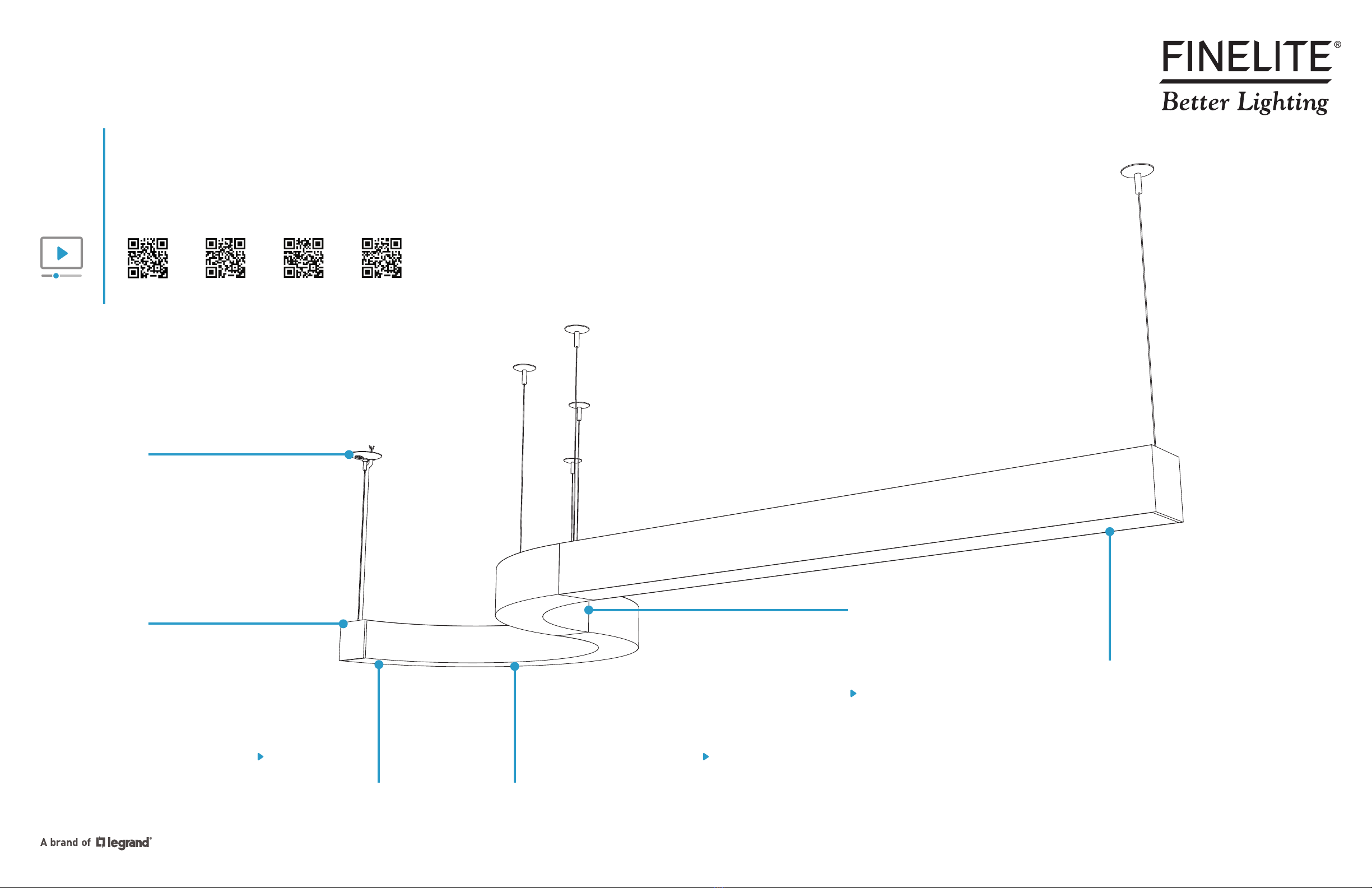
HP-4 D - 32' - S - 835 - 120V - SC
HP-4 D - X'
ID: 1
STARTER
A. Identify Luminaires
Factory Order
Number
Job Name
Unique Luminaire
ID Number
Full Catalog
Order ID
Luminaire
Section Type
Luminaire Type
and/or Run Length
Kitted Hardware
• Finelite has provided
items listed here, with
their Finelite part numbers.
These items can be found
in separate boxes shipped
with the luminaire.
• Account for all parts
and set aside until they
are needed.
• All other hardware needed
for this installation will be
by others.
Caddy Clip
C1 Ceiling - Part# 94001
C2 Ceiling - Part# 94020
C3 Ceiling - Part# 94029
Mounting & Suspension
p. 2, Step 1
2" Drywall Support Canopy
Part# 94017
Mounting Luminaires to Structure
p. 7, Step 3
5" Canopy
5" Dual Feed Canopy
Part# 94085
Part# 94145
Mounting Luminaires to Structure
p. 7-8, Step 3
GridBox™
Dual GridBox™
Part# 89159
Part# 89199
Mounting & Suspension
p. 2, Step 1
Mounting Luminaires to Structure
p. 8, Step 3
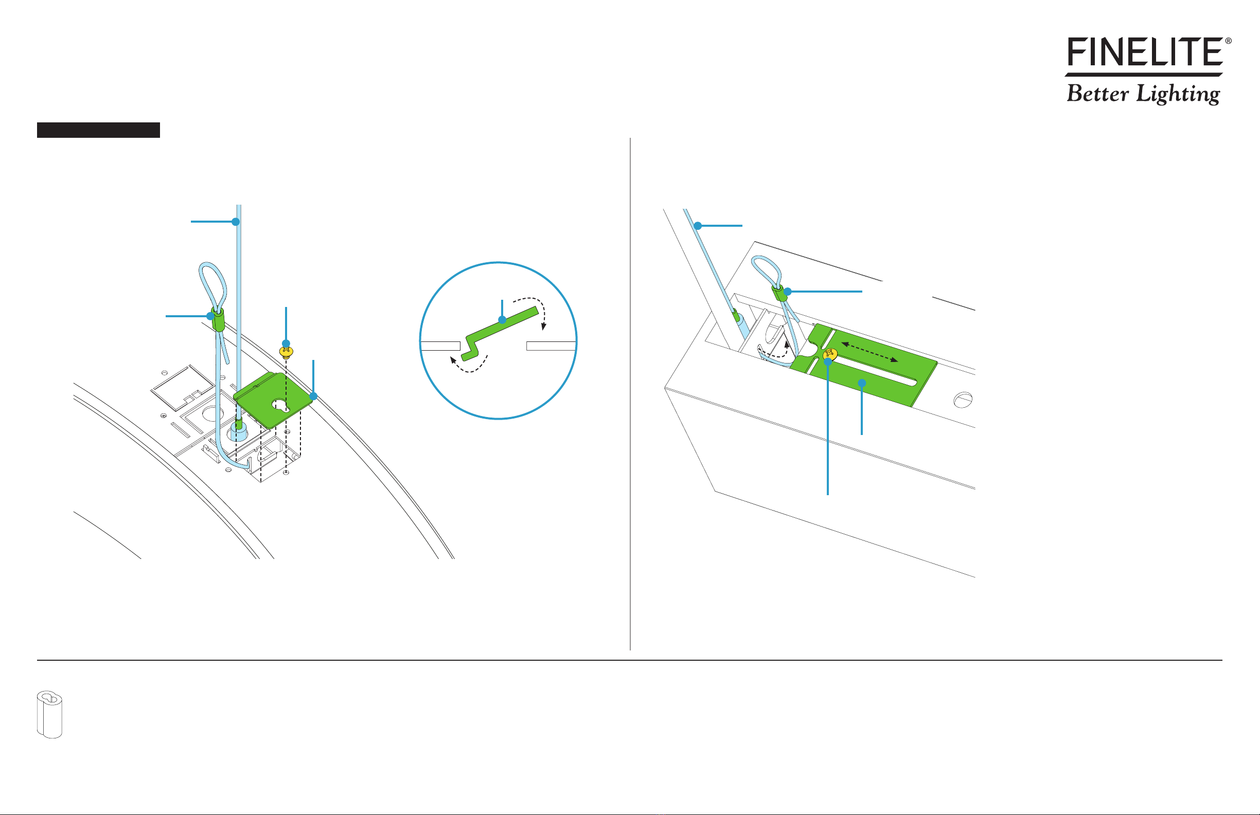
Safety Crimp
Part# 94514
Closing Luminaires
p. 11, Step 7
3-1/2" Canopy
3-1/2" Dual Feed Canopy
Part# 89191
Part# 89192
Mounting Luminaires to Structure
p. 7-8, Step 3
2" T-Bar Support Canopy
Part# 89193
Mounting Luminaires to Structure
p. 7, Step 3
Mounting Option 2Mounting Option 1
Cable Bushing
Aircraft Cable
Part# 94014
50" - Part# 94515-12 (Std.)
100" - Part# 94515-14
150" - Part# 94515-18
Mounting Luminaires to Structure
p. 7, Step 3
Closing Luminaires
p. 11, Step 7
Slip Ring w/ Set Screw
Part# 94015
Mounting Luminaires to Structure
p. 7, Step 3
Yoke Bracket
Washer
#10-32 x 5/8" Screw
Part# 47130
Part# 94111
Part# 94144
Securing Luminaire Joints
p. 10, Step 6
• Identify all luminaires by their ID label that can be found on the box and inside the luminaire.
• NOTE: Exact location of labels in these areas may vary.
• Remove all luminaires from their box.
• Refer to Record Drawings that can be found in the hardware kit.
Step 2 - Identification & Preparation
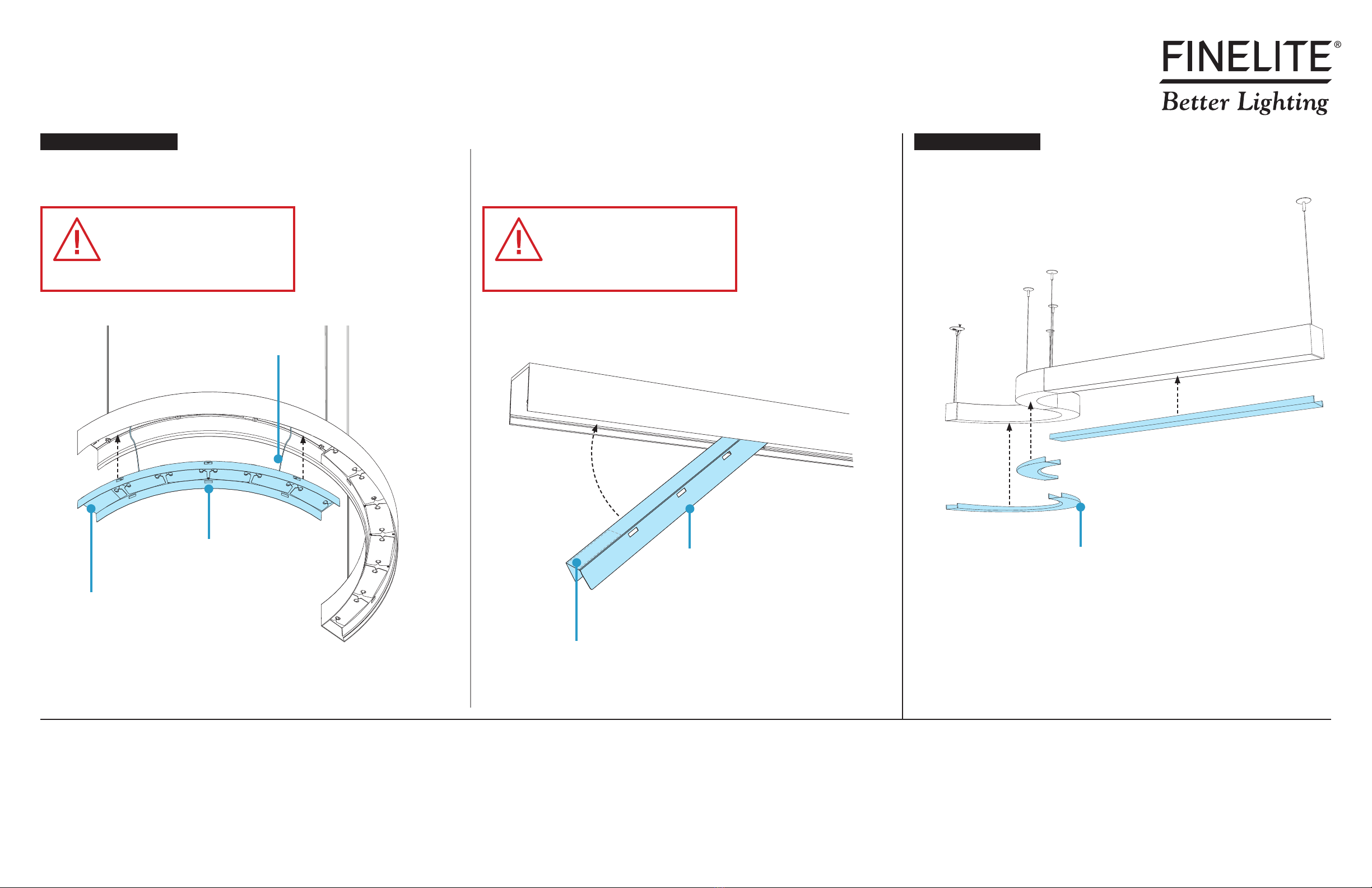
B. Remove Diffuser
Putty Knife
(Outer Edge)
Diffuser Diffuser
Protective Bag
Backplate
ID Label
ID Label
Top-Down View
• NOTE: Maximum width of putty knife is 2 inches.
• 1. To release diffuser, carefully slide putty knife between outer edge of diffuser and luminaire.
• 2. Then, directly across from you carefully slide putty knife between inner edge of diffuser and luminaire.
• 3. Work your way around outer edge of diffuser to fully release it from luminaire.
• Keep diffuser inside protective bag.
• Set aside diffuser to prevent it from getting dirty or damaged.
• Ensure diffuser can be clearly identified back to corresponding luminaire.