GE Current Tetra Slim EdgeStrip Series User manual

BEFORE YOU BEGIN
Read these instructions completely and carefully.
Tetra®Slim EdgeStrip
LED Lighting System
(GE12BI71-S1, GE12BI50-S1, GE12BI41-S1, GE12BI32-S2)
Installation Guide
12
Volt
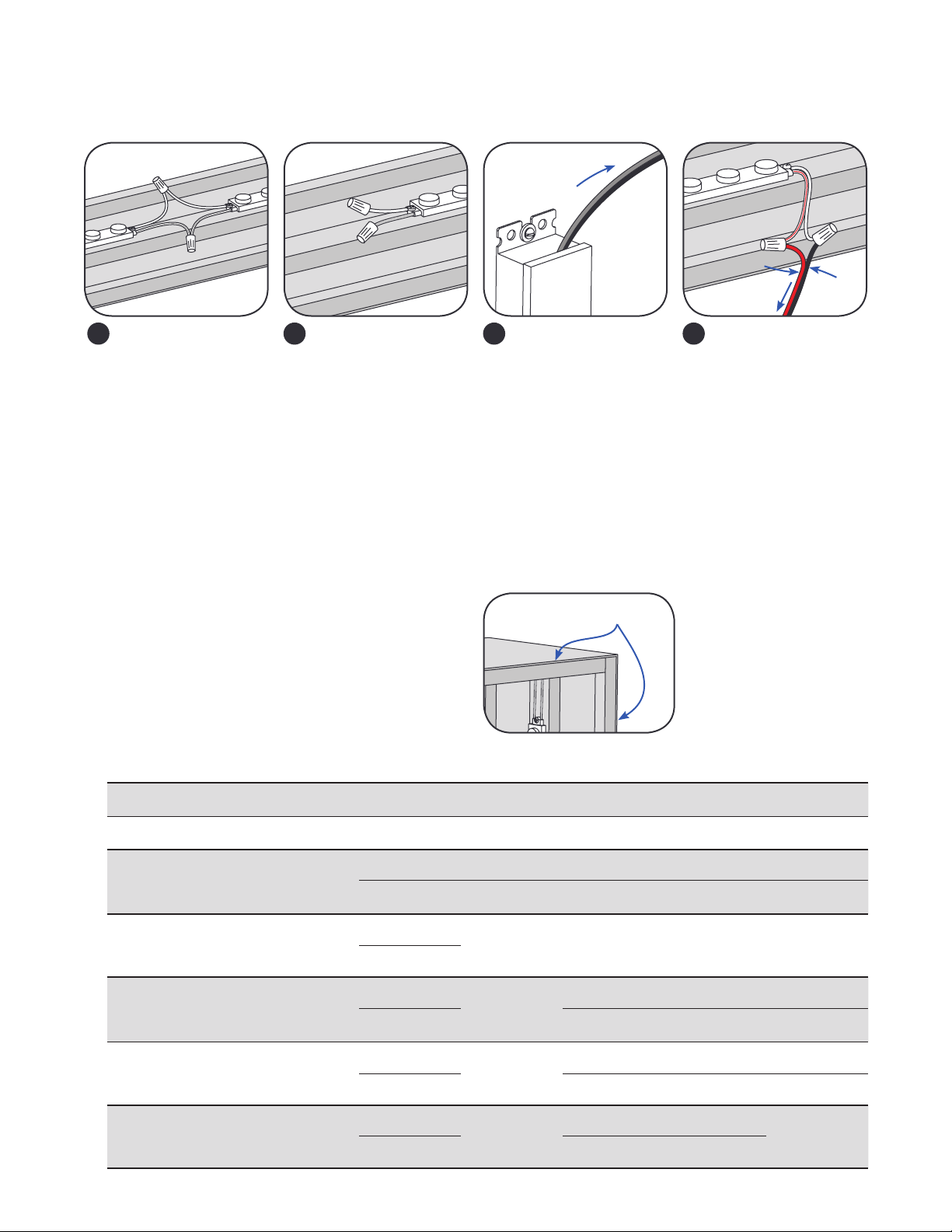
Prepare Electrical Wiring
Electrical Requirements
• Limited to use in dry and damp locations. The suitability of
rain enclosures shall be determined if intended for wet location.
• The grounding and bonding of the LED Driver shall
be done in accordance with National Electric Code (NEC)
Article 600.
• Follow all National Electric Codes (NEC) and local codes.
• These products are only suitable for connection to a circuit
from a Class 2 power source. These products have not been
evaluated for use when connected to a power source that does
not comply with Class 2 voltage and energy limited supplies.
Save These Instructions
Use only in the manner intended by the manufacturer.
If you have any questions, contact the manufacturer.
This device complies with part 15 of the FCC Rules. Operation is subject to the following two conditions: (1) This device may not cause harmful interference, and
(2) this device must accept any interference received, including interference that may cause undesired operation.
Note: This equipment has been tested and found to comply with the limits for a Class A digital device, pursuant to part 15 of the FCC Rules. These limits are
designed to provide reasonable protection against harmful interference when the equipment is operated in a commercial environment. This equipment generates,
uses, and can radiate radio frequency energy and, if not installed and used in accordance with the instruction manual, may cause harmful interference to radio
communications. Operation of this equipment in a residential area is likely to cause harmful interference in which case the user will be required to correct the
interference at his own expense.
This Class [A] RFLD complies with the Canadian standard ICES-005. Ce DEFR de la classe [A] est conforme à la NMB-005 du Canada.
EN Instruction Guide
AR
BG Инструкции за монтаж
CS Montážní příručka
DA Monteringsvejledning
DE Einbauanleitung
EL ΟδηγόςΕγκατάστασης
ES Guía de instalación
ET Paigaldusjuhend
FI Asennusohje
FR Guide d’installation
HR Priručnik za instalaciju
HU Felszerelési útmutató
IT Guida all’installazione
LT Sumontavimo vadovas
LV Uzstādīšanas instrukcija
NL Installatiehandleiding
NO Monteringsanvisning
PL Instrukcja instalacji
PT Guia de Instalação
RO Ghid de instalare
RU Инструкции по установке
SV Installationsanvisning
SL Navodila za namestitev
SK Návod na inštaláciu
TR Montaj Kılavuzu
UK Посібник з установлення
ZH 安装指南
ﺐﻴﻛﺮﺘﻟا ﻞﻴﻟد
RETROFIT SIGN CONVERSION LED KIT FOR USE ONLY IN
ACCORDANCE WITH KIT INSTRUCTIONS.
KIT IS COMPLETE ONLY WHEN ALL PARTS REQUIRED BY
THE INSTRUCTIONS ARE PRESENT.
TROUSSE DE CONVERSION À DEL POUR LA
MODERNISATION DES ENSEIGNES
À UTILISER CONFORMÉMENT AU GUIDE D’INSTALLATION.
WARNING/AVERTISSEMENT
RISK OF ELECTRIC SHOCK
∙Turn power off before inspection, installation or
removal.
∙Properly ground GE power supply enclosure.
RISK OF FIRE
∙Use only UL approved wire for input/output
connections. Minimum size 18 AWG (0.82mm2)
∙Follow all NEC and local codes.
∙Not to be submerged or used in a marine environment.
RISK OF FIRE OR ELECTRIC SHOCK
∙LED Retrot Kit installation requires knowledge of sign
electrical systems. If not qualied, do not attempt
installation. Contact a qualied electrician.
∙Install this kit only in host signs that have been identied
in the installation instructions and where the input rating
of the retrot kit does not exceed the input rating of the
sign.
∙Installation of this LED retrot kit may involve drilling or
punching of holes into the structure of the sign. Check
for enclosed wiring and components to avoid damage
to wiring and electrical parts.
∙Do not make or alter any open holes in an enclosure of
wiring or electrical components during kit installation.
RISQUES DE DÉCHARGES ÉLECTRIQUES
∙Coupez l’alimentation avant l’inspection, l’installation ou le déplacement.
∙Assurez-vous de correctement mettre à terre l’alimentation électrique GE.
RISQUES D’INCENDIE
∙N’utilisez que des ls approuvés par UL pour les entrées/sorties de connexion.
Taille minimum 18 AWG (0.82mm2)
∙Respectez tous les codes NEC et codes locaux.
∙Ne pas submerger ou installer dans un environnement marin.
RISQUE D’INCENDIE OU DE CHOC ÉLECTRIQUE
∙L’installation de l’équipement de remplacement DEL exige Ia connaissance des
systèmes électriques pour enseignes. Si non qualié, ne tentez pas d’installation.
Veuillez contacter un électricien qualié.
∙Risque d’incendie ou de choc Électrique. Installez cet ensemble seulement dans
des enseignes hôtes qui ont été identiés dans les instructions d’installation et
dont la capacité d’entrée de l’ensemble ne dépasse pas la capacité d’entrée de
l’enseigne.
∙L’installation de cet équipement de remplacement DEL peut impliquer le perçage
ou le poinçonnage de trous dans la structure du panneau Vériez le câblage et
les composants inclus pour éviter d’endommager le câblage et les composants
électriques.
∙Ne pas faire ou modier les trous ouverts dans une enceinte de câblage
ou de composants électriques pendant l’installation de cet équipement de
remplacement DEL.
1

Peel off backing to expose adhesive tape and stick
LED modules into place.
Determine how many modules are required for
your application and cut where necessary.
NOTE: Cuts can be made between any of the LED
modules.
Determine location of where LED modules will be
mounted based on sign dimensions (see chart).
If mounting on bottom of sign, the use of a riser
will be needed (minimum 1/8 in. distance between
bottom surface and module).
3
21
4
Layout LED Modules
Sign
Modules mounted to sides
Use rivets, screws, or silicone to secure each
module within the sign. Use #6 (M3) or #8 (M4)
screws, 1/8-inch (3.2 mm) rivets, or silicone.
Components and Tools Required
5
1
2
3
4
UL approved 18 AWG (0.82 mm2) supply wire
UL approved 22-14 AWG (0.33-2.08 mm2) wire
connectors or 22-18 AWG (0.33-0.82 mm2) in-line/
IDC connectors
#6 or #8 (M3 or M4) screws, 1/8 inch
(3.2 mm) rivets or electrical grade silicone
3
2
1 4
Tetra®12 Volt Power Supply
Tetra®Slim EdgeStrip LED modules
Electrical grade RTV silicone.
Example electrical grade RTV silicones include:
• Momentive RTV 6700 Series Silicone Rubber Adhesive Sealant
• Momentive White Blanc RTV 162 Silicone Rubber Adhesive Sealant-
Electrical Grade
• Dow Corning 3140 - Non-Corrosive Flowable (clear)
• Dow Corning 3145 - Non-Corrosive Nonowable (clear or gray)
• Dow Corning RTV 748 Non-Corrosive Sealant-White
5
TCMeasure Point
6
6
2

Design Guidelines
All guidelines are based on a 3 in. (76mm) deep
sign for Tetra®Slim EdgeStrip. When installing the
modules, it is typically recommended to install the
modules across the longest distance to allow for the
shortest light throw.
A 2 in. (51 mm) border is
recommended along the
perimeter of the sign.
2 inches
3Connect the red stripe
wire (+) of the LED system
to the red wire (+) of the
power supply. Connect
the white wire (-) of the
LED system to the black
or blue wire (-) of the
power supply.
4
Power
Supply
To LED System
Red (+)
Black or
blue (–)
Run a wire from the
Power Supply and
connect to the rst LED
module on the strip.
Must be used with
Tetra®12 Volt Power
Supplies.
To Power
Supply
Connect modules
using twist-on wire
connectors or in-line
(IDC) connectors. Join
white wires together
and red striped wires
together.
NOTE: Additional supply
wire may be necessary
to bridge electrical
connections.
Cap all exposed wires
with appropriate wire
connectors or apply
electric grade (non-
corrosive) silicone for
additional weather
protection.
1 2
Electrical Connections
NOTE: Do not use connectors pre-lled with silicone grease/mineral base protective grease or use silicone grease to seal connections.
NOTE: All electrical connections should be suitably protected from mechanical damage
and the environment. Seal all connections in locations that may be exposed to water with
electrical grade RTV silicone.
3
Height
1 ft. (0.30 m) 2 ft. (0.62 m) 3 ft. (0.91 m) 4 ft. (1.22 m) 5 ft. (1.52 m) 6 ft. (1.83 m) 7 ft. (2.13 m)
Width
1 ft.
(0.30 m)
3-8” - 2 mods
on one side
3-8” - 3 mods
on one side
3-8” - 5 mods
on one side
3-8” - 6 mods
on one side
3-8” - 8 mods
on one side
3-8” - 9 mods
on one side
3-8” - 11 mods
on one side
2 ft.
(0.62 m)
3-8” - 3 mods
on one side
3-8” - 3 mods
on one side
3-8” -5 mods
on one side
3-8” - 6 mods
on one side
3-8” - 8 mods
on one side
3-8” - 9 mods
on one side
3-8” - 11 mods
on one side
3 ft.
(0.91 m)
3-8” - 5 mods on
one side
3-8” - 5 mods on
one side
3-5” - 5 mods
on two sides
3-5” - 5 mods
on two sides
3-5” - 8 mods
on two sides
3-5” - 9 mods
on two sides
3-5” - 11 mods
on two sides
5-8” - 5 mods
on one side
5-8” - 6 mods
on one side
5-8” - 8 mods
on one side
5-8” - 9 mods
on one side
5-8” - 11 mods
on one side
4 ft.
(1.22 m)
3-8” - 6 mods
on one side
3-8” - 6 mods
on one side
3-5” - 5 mods
on two sides 3-8” - 6 mods
on two sides
3-8” - 8 mods
on two sides
3-8” - 9 mods
on two sides
3-8” - 11 mods
on two sides
5-8” - 6 mods
on one side
5 ft.
(1.52 m)
3-8” - 8 mods
on one side
3-8” - 8 mods
on one side
3-5” - 8 mods
on two sides 3-8” - 8 mods
on two sides
3-5” -
Not Recommended
3-5” -
Not Recommended
3-5” -
Not Recommended
5-8” - 8 mods
on one side
5-8” - 8 mods
on two sides
5-8” - 9 mods
on two sides
5-8” - 11 mods
on two sides
6 ft.
(1.83 m)
3-8” - 9 mods
on one side
3-8” - 9 mods
on one side
3-5” - 9 mods
on two sides 3-8” - 9 mods
on two sides
3-5” -
Not Recommended
3-5” -
Not Recommended
3-5” -
Not Recommended
5-8” - 9 mods
on one side
5-8” - 9 mods
on two sides
5-8” - 9 mods
on two sides
5-8” - 11 mods
on two sides
7 ft.
(2.13 m)
3-8” - 11 mods
on one side
3-8” - 11 mods
on one side
3-5” - 11 mods
on two sides 3-8” - 11 mods
on two sides
3-5” -
Not Recommended
3-5” -
Not Recommended 3-8” -
Not Recommended
5-8” - 11 mods
on one side
5-8” - 11 mods
on two sides
5-8” - 11 mods
on two sides

Troubleshooting
Symptom Solution
Row of modules does not light • Check wire connections to power supply to ensure red stripe-to-red and white-to-black or blue connections.
• Check row-to-row polarity connections.
Sign does not light • Check input and output voltage and check power supply input/output connections.
• Check polarity connections.
• Ensure the overall length of the Tetra® LED System does not exceed the maximum load.
Individual modules do not light • Remove module and replace with another working module.
Modules are dim • Ensure the overall length of the Tetra®LED system does not exceed the maximum load.
• Ensure the length and gauge of the supply wire is equal to or below the recommended remote mounting distance.
Specications
Maximum Remote Mounting Distance
18 AWG/0.82 mm2
Supply Wire 16 AWG/1.31 mm2
Supply Wire 14 AWG/2.08 mm2
Supply Wire 12 AWG/3.31 mm2
Supply Wire
25W Power Supply 120 ft./36.6 m – – –
60W Power Supply 20 ft./6.1 m 30 ft./9.1 m 50 ft./15.2 m 86 ft./26.2 m
180W Power Supply 20 ft./6.1 m 30 ft./9.1 m 50 ft./15.2 m 86 ft./26.2 m
Maximum Loading per Tetra®12 VDC Power Supply
SKU Rating
25W Power Supply
Note: Load shall not
exceed 2A
60W Power Supply
Note: Load shall not
exceed 5A
180W Power Supply
Note: Load shall not exceed 5A
per each (of 2) output channels
GE12BI71-S1
GE12BI50-S1
GE12BI41-S1
GE12BI32-S1
12VDC, 1.56W
per module
12 modules/8 ft.
(2.44 m)
30 modules/20 ft.
(6.09 m)
30 modules/20 ft. (6.09 m)
per output channel
90 modules/60 ft. (18.29 m)
per power supply
This product is intended solely for the use of non-residential signage lighting and is not intended for use in any other applications.
Conforms to the following standards:
IP66 rated: separate enclosure required for outdoor use, UL damp location rated
Retrot Instructions
1. (Existing Signs Only) Prior to installation, survey the site for information regarding power and accessibility inside and outside the building. Ensure
that the branch circuit supplying the existing transformer or ballast will be within the voltage ratings of the new LED power supply, and have
a current rating not exceeding 20A, or that permitted by applicable local, state, or country electrical codes (whichever is less).
2. (Existing Signs Only) Remove the existing lighting equipment to be replaced, such as neon tubing or uorescent tubes; and associated
transformers and ballasts. Care should be taken not to break the existing neon or uorescent tubes.
NOTE: Follow all federal and local regulations when disposing of neon tubing, uorescent tubes, transformers and ballasts.
3. (Existing Signs Only) If removal of the existing lighting equipment eliminates the disconnect switch, as required by applicable local, state, or
country electrical codes; a new disconnect switch must be installed.
4. (Existing Signs Only) Repair and seal any unused openings in the electrical enclosure. Openings greater than 12.7-mm (1/2-in) diameter require a
metal patch secured by screws or rivets and caulked with non-hardening caulk. Smaller openings may be sealed with non-hardening caulk.
5. Using the layout guidelines above, determine required number of LED modules required to illuminate the sign.
6. A Tetra® 12VDC Class 2 Power Supply, as listed below, must be used with this retrot kit. Using the Maximum Loading chart below, determine the
number of Tetra®Class 2 Power Supplies required to power the number of LED modules required to illuminate the sign, so as not to overload
the Tetra®Class 2 Power Supply chosen.
7. Follow the instructions above to properly mount the LED modules.
8. Connect the DC output of the power supply to the LED modules using the Electrical Connections instructions above.
9. Connect the power unit to the supply in accordance with the applicable local, state, and country electrical codes, and the instructions found in the
power supply installation guide.
10. If required, the disconnect switch shall be installed by qualied personnel, in accordance with applicable local, state, and country electrical codes.
If you have any questions about these instructions or your specic application, please contact support at [email protected].
For the latest install guides for your product go to: www. LED.com
All trademarks are the property of their respective owners. Information provided is subject to
change without notice. All values are design or typical values when measured under laboratory
conditions. Current, powered by GE is a business of the General Electric Company.
© 2019 GE.
www.LED.com SIGN097 (Rev 08/27/19) GE2030-1370
III
This manual suits for next models
4
Table of contents
Other GE Lighting Equipment manuals

GE
GE LED G90 8L Lawn Stakes User manual

GE
GE LED7-C7-50 User manual

GE
GE 19005LO User manual

GE
GE Tetra EdgeStrip HO User manual

GE
GE HO HO HO User manual

GE
GE ProSys DEH40206 User manual

GE
GE GEMX50-W1 User manual

GE
GE Lumination L-TC-ID-A-1 J1 Series User manual

GE
GE 23071LO User manual

GE
GE LEDa-G90-8 User manual

GE
GE LED 500 LIGHTS User manual

GE
GE Arize Element Series User manual

GE
GE Tetra GETP35-2 User manual

GE
GE Arize Factor HORT171 User manual

GE
GE 77007LOSS User manual

GE
GE 24LEDI-C4-11000.4 User manual

GE
GE LED-C6-150 User manual

GE
GE FPH-50 User manual

GE
GE Tetra PowerGrid-Gen 3 User manual

GE
GE 78937 User manual