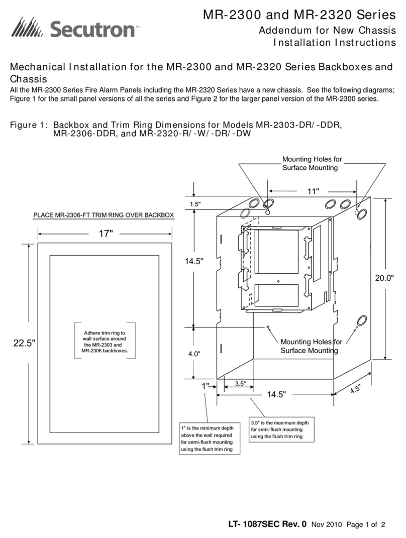
FireClass FC420CP User manual

ITALIANO
Codice d'ordine: 514.800.803
0832
BENTEL SECURITY s.r.l.
Via Gabbiano, 22 - Zona Ind. S. Scolastica
64013 Corropoli (TE) - ITALY
09
0832-CPD-1281
EN 54-11
Pulsante manuale per sistemi di rivelazione e di
segnalazione incendio negli edifici
Tipo A da interno
FC420CP
SPECIFICHE TECNICHE
Valore Identificativo: 129
Compatibilità: usare solo con Centrali serie FC
Caratteristiche ambientali: Solo per applicazioni interne
Temperatura di funzionamento: da -10 a +55 oC
Temperatura di stoccaggio: da -30 a +70 oC
Umidità relativa:fino a 95% (senza condensa)
Dimensioni (HxLxP): 93 x 89 x 59,5 mm
(27,5 mm se incassato)
Corrente assorbita
a Riposo:
in Allarme:
0,46 mA
4,5 mA
Tensione Loop: Min. Tip. Max.
20 37,5 38,4
ENGLISH
Ordering Code: 514.800.803
0832
BENTEL SECURITY s.r.l.
Via Gabbiano, 22 - Zona Ind. S. Scolastica
64013 Corropoli (TE) - ITALY
09
0832-CPD-1281
EN 54-11
Manual call point for fire detection & fire alarm systems for
buildings
Type A indoor
FC420CP
TECHNICAL SPECIFICATION
Type Identification Value: 129
System Compatibility: Use only with FC Fire Alarm Controllers
Environment: Indoor Application only
Operating Temperature: -10 to +55 oC
Storage Temperature: -30 to +70 oC
Operating Humidity: Up to 95% non-condensing
Dimensions (HxWxD): 93 x 87 x 59.5 mm
(27.5 mm if flush mounted)
Battery Requirements
Standby:
Alarm:
0.46 mA
4.5 mA
Loop Voltage: Min. Typ. Max.
20 37.5 38.4
TERMINALI VOLANTI
FLYING LEADS
ALLOGGIAMENTO DEL PCB
PCB CRADLE
INDICATORE D’ALLARME
LED (ROSSO)
ALARM INDICATOR
LED (RED)
RILASCIO TEST
ACCESSO CHIAVE
TEST/RELEASE
KEY ACCESS
Pulsante a Rottura Vetro - FC420CP FIG. 1 FC420CP - Break Glass Callpoint
FC420CP
PULSANTE A ROTTURA VETRO INDIRIZZABILE DA INTERNO
ADDRESSABLE BREAK GLASS CALLPOINT (INDOOR)
ISTISBL3FC420CP 6.0 160212
LEAFLET 120.415.975-i6

Electromagnetic Compatibility
The FC420CP complies with the following:
Øproduct family standard EN50130-4 in respect of Conducted
Disturbances, Radiated Immunity, Electrostatic Discharge,
Fast Transients and Slow High Energy;
ØEN61000-6-3 for emissions.
INTRODUCTION
FC420CP Addressable Break Glass Callpoint is designed to mon-
itor and signal the condition of a switch contact that is operated by
activating the break glass element. The glass element may be re-
placed with a deformable plastic element which allows the
FC420CP device to be reset, using the key supplied, after alarm
activation. The type of alarm generated by the callpoint is config-
ured in FireClass Console.The FC420CP call point meets the re-
quirements of EN54 Pt.11. The FC420CP is fitted to a standard
surface mount plastic backbox, standard single gang metal plaster
box (35 mm for flush mounting) or standard single gang metal
plaster box (25 mm) with backbox.
+Note: plaster boxes should have 20 mm knockouts.
ADDRESS PROGRAMMING
The FC420CP has a default factory set address of 255, this must be
set to the loop address of the device using FC490ST Loop Service
Tool. The FC420CP is programmed with its address using the pro-
gramming port at the rear of the callpoint before mounting to the
backbox as shown in Fig. 3.
+Note: once the address has been programmed take note of the
device location and address number to include on site drawings.
MOUNTING
Mount to a standard break glass callpoint housing, or standard
single gang metal plaster box (35 mm for flush mounting or 25
mm) with standard break glass callpoint housing.
CABLING
Cables are to be selected in accordance with the FireClass design
document .Cabling should be connected as shown in Fig. 5 ensur-
ing correct polarity. Couplers are to be used with MICC cable.
WIRING NOTES
1) There are no user-required settings (such as switches or head-
ers) on the FC420CP.
Compatibilità Elettromagnetica
Il modulo FC420CP è conforme a quanto segue:
Øfamiglia di prodotto standard EN50130-4 rispetto alle Perturba-
zioni Dirette, Immunità Irradiata, Scarica Elettrostatica, Transi-
torie Rapide e Alta Energia Lenta;
ØEN 61000-6-3 per le emissioni.
INTRODUZIONE
Il pulsante a rottura vetro indirizzabile FC420CP è progettato per monito-
rare e segnalare lo stato di un interruttore che è attivato dalla rottura del
vetrino. È possibile sostituire il vetrino con un elemento plastico deforma-
bile che permette, dopo l'attivazione dell'allarme, il ripristino del pulsante
FC420CP tramite la chiave in dotazione. Il tipo di allarme generato dal
pulsante è configurabile con FireClass Console. Il pulsante FC420CP
soddisfa i requisiti EN54 Pt.11. Il pulsante FC420CP può essere fissato
ad una scatola standard per il montaggio a parete di materiale plastico,
ad una scatola americana single-gang da incasso, di metallo (da 35 mm
per il montaggio ad incasso) o ad una scatola americana single-gang da
incasso, di metallo, da 25 mm, tramite una scatola standard.
+Le scatole da incasso devono avere fori a sfondamento da 20 mm.
PROGRAMMAZIONE
L'indirizzo di fabbrica del FC420CP è 255, questo deve essere impo-
stato all'indirizzo di loop del dispositivo tramite lo strumento per la pro-
grammazione dei dispositivi indirizzabili FC490ST. L'indirizzo del
FC420CP può essere programmato usando la porta di programma-
zione posteriore prima del montaggio della scatola (vedere Fig. 3).
+Nota: una volta programmato l'indirizzo, annotare la posizione del
dispositivo e l'indirizzo, per segnarlo sul progetto dell'impianto.
MONTAGGIO
Montare su un contenitore standard per pulsanti a rottura vetro, o
su una scatola americana single-gang da incasso, di metallo da
35 mm, per il montaggio ad incasso, o da 25 mm con un contenito-
re standard per pulsanti a rottura vetro.
COLLEGAMENTI
I cavi devono essere selezionati in conformità con il documento di pro-
gettazione del sistema FireClass. I collegamenti devono essere effet-
tuati come mostrato in Fig. 5 rispettando la corretta polarità. Usare degli
accoppiatori con cavi MICC (cavi in rame con isolamento minerale).
NOTE PER IL COLLEGAMENTO
1) Sul FC420CP non ci sono regolazioni da effettuare (interruttori
o altro).
FC420CP–Dimensioni fissaggio per il montaggio a pareteFIG. 2
FC420CP – Fixing Dimensions Surface Mounting
PORTA PER LA PROGRAMMAZIONE
DELL’INDIRIZZO
ADDRESS PROGRAMMING PORT
Porta per la programmazione dell'indirizzo del FC420CPFIG. 3
FC420CP – Address Programming Port

2) Nessun conduttore deve essere collegato a terra. Per lo sche-
ma di collegamento tipico, vedere Fig.5.
3) Verificare la corretta polarità dei collegamenti prima di collega-
re il FC420CP al circuito loop indirizzabile. Fissare il contenito-
re del pulsante a rottura vetro al fondo.
INFORMAZIONI PER L'ORDINE
FC420CP: Pulsante a rottura vetro.
515.001.119:Vetrini di ricambio (confezione da 5).
515.001.127:Elemento di attivazione deformabile.
FC420CPB: Contenitore standard per pulsanti a rottura vetro.
INFORMAZIONI SUL RICICLAGGIO
Si consiglia ai clienti di smaltire i dispositivi usati (centrali, rilevato-
ri, sirene, accessori elettronici, ecc.) nel rispetto dell'ambiente.
Metodi potenziali comprendono il riutilizzo di parti o di prodotti inte-
ri e il riciclaggio di prodotti, componenti e/o materiali.
DIRETTIVA RIFIUTI DI APPARECCHIATURE ELETTRICHE
ED ELETTRONICHE (RAEE - WEEE)
Nell'Unione Europea, questa etichetta indica che que-
sto prodotto NON deve essere smaltito insieme ai ri-
fiuti domestici. Deve essere depositato in un impianto
adeguato che sia in grado di eseguire operazioni di re-
cupero e riciclaggio.
Il costruttore si riserva il diritto di modificare le specifiche tecniche
di questo prodotto senza preavviso.
2) All conductors to be free of earths. For typical wiring configura-
tion, see Fig. 5.
3) Verify the correct polarity of wiring before connecting the
FC420CP to the addressable loop circuit. Fit the callpoint
housing to the backbox.
ORDERING INFORMATION
FC420CP: Break Glass Callpoint.
515.001.119:Spare Glass (pack of 5).
515.001.127:Deformable Activation Element.
FC420CPB: Standard break glass callpoint housing.
RECYCLING INFORMATION
Customers are recommended to dispose of their used equipments
(panels, detectors, sirens, and other devices) in an environmentally
sound manner. Potential methods include reuse of parts or whole
products and recycling of products, components, and/or materials.
WASTE ELECTRICAL AND ELECTRONIC EQUIPMENT
(WEEE) DIRECTIVE
In the European Union, this label indicates that this
product should NOT be disposed of with household
waste. It should be deposited at an appropriate facility
to enable recovery and recycling.
The manufacturer reserves the right to change the technical speci-
fications of this product without prior notice.
Ingombro e dimensioni di fissaggio FIG. 4 Overall and Fixing Dimensions
CENTRALE FC
FC CONTROLLER
AL DISPOSITIVO SUCCESSIVO
TO NEXT DEVICE
TERMINALI VOLANTI
FLYING LEADS
NERO / BLACK
+L1
-L1
LEFT
ROSSO / RED
+L1
-L1
Schema di collegamento semplificato del FC420CP FIG. 5 FC420CP – Simplified wiring diagram

123
Test FC420CP FIG. 6 FC420CP Test
123
456
Sostituzione vetrino FC420CP FIG. 7 FC420CP Replacing Glass
3
2
1
Reset FC420CP FIG. 8 FC420CP Reset
© FireClass
Via Gabbiano 22, Z. Ind. S. Scolastica
64013 Corropoli (TE), Italy
Hillcrest Business Park Cinderbank
Dudley West Midlands
DY2 9AP United Kingdom
www.fireclass.co.uk
Other FireClass Fire Alarm manuals
FireClass
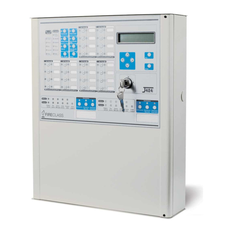
FireClass J400 User manual
FireClass
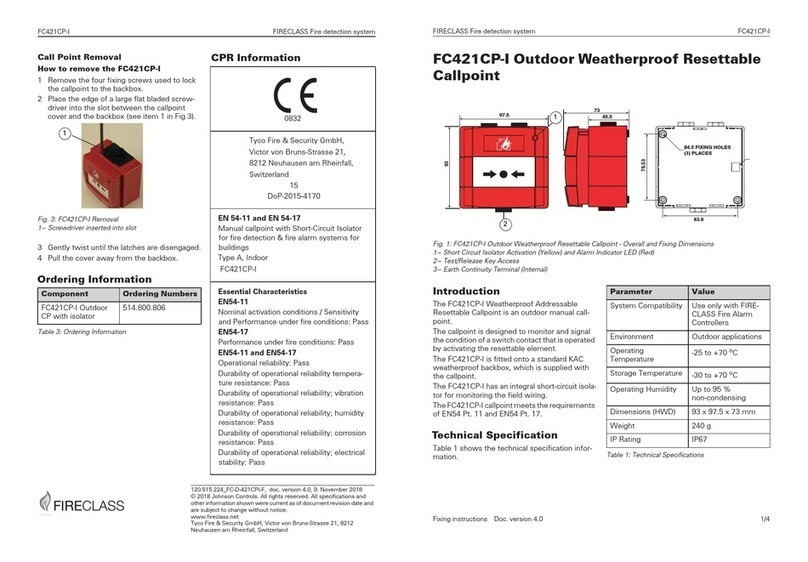
FireClass FC421CP-I Manual

FireClass
FireClass Prescient III Guide
FireClass
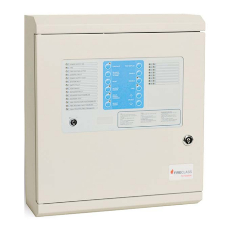
FireClass Precept EN13 Guide

FireClass
FireClass MCP200CS User manual
FireClass
FireClass FC430SB User manual
FireClass
FireClass DUO-CEL User guide
FireClass
FireClass Lite 1.0 User manual
FireClass
FireClass Precept EN Panel Guide
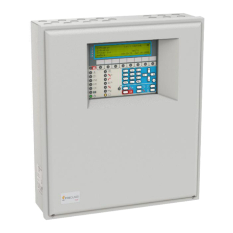
FireClass
FireClass FC503 User manual
Popular Fire Alarm manuals by other brands
System Sensor
System Sensor SP2R Installation and maintenance instructions

Notifier
Notifier AM2020 manual
Cooper Notification
Cooper Notification Wheelock MPS Series installation instructions

Simplex
Simplex 4903 installation instructions

Tyco
Tyco TIS-BG12LX manual
Tyco Fire Product
Tyco Fire Product Alpha 4 Installation and operating instructions
