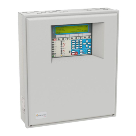
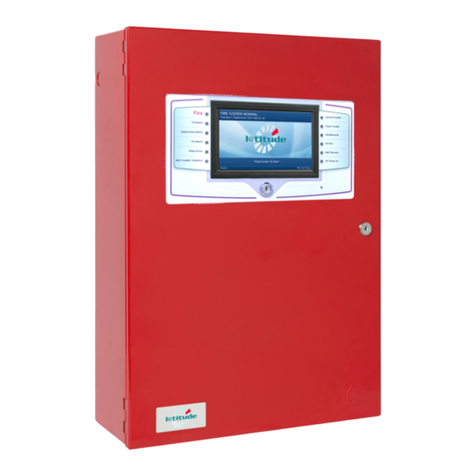
FireClass Lite 1.0 User manual

Product Information and
Design Application
120.515.093
Doc. version 1.0
25. April 2012
FireClass Lite®
FireClass Addressable Fire
Alarm Control Panels
version 1.0

© FIRECLASS. Hillcrest Business Park, Dudley, West Midlands, DY2 9AP, UK, 2012
Contents subject to change without notice.
All rights to this documentation, including the contents of the online help, are reserved, in particular but not limited to the
rights of copying, distribution and translation.
No portion of this documentation, including the online help, may be reproduced, edited, copied or distributed in any form
without prior written authorization from FIRECLASS. Use of the data medium provided with this product is restricted to cop-
ying the software for the purpose of data backup only.

FireClass Fire detection system FireClass Panels Contents
Product Information and Design Application Doc. version 1.0 3
Contents
1 Guide through this manual ............................................................................................ 5
1.1 Keywords and symbols ................................................................................................................5
1.2 Helpful information .......................................................................................................................5
1.3 Purpose...........................................................................................................................................5
1.4 Who this guide is for .....................................................................................................................5
1.5 Reference Documents ..................................................................................................................5
2 Control Panel and Associated Housing........................................................................ 6
2.1 Key Functions and Features.........................................................................................................6
2.1.1 General Description-Panel and Repeater .........................................................................................................................................6
2.2 FireClass Lite Express ...................................................................................................................6
2.2.1 FIM Connection Details........................................................................................................................................................................ 10
2.3 Summary ..................................................................................................................................... 11
2.4 Collected Specifications............................................................................................................ 11
2.4.1 Shock/Vibration...................................................................................................................................................................................... 11
2.4.2 Dimensions ............................................................................................................................................................................................... 11
2.4.3 Colour..........................................................................................................................................................................................................11
2.4.4 Battery Details.......................................................................................................................................................................................... 11
2.4.5 PSU ..............................................................................................................................................................................................................11
2.4.6 PMM800 Power Monitoring Module ............................................................................................................................................12
2.4.7 Siting Considerations............................................................................................................................................................................ 12
2.4.8 Environmental Stipulations.................................................................................................................................................................12
2.4.9 EMC .............................................................................................................................................................................................................12
2.5 Component Module Descriptions............................................................................................. 12
2.5.1 Central Processing Unit........................................................................................................................................................................ 12
2.5.2 Field Interface Module (FIM) .............................................................................................................................................................. 12
2.5.3 Display and Control Module...............................................................................................................................................................13
2.6 Unavailable Features for FireClass Lite.................................................................................... 13
2.7 Ordering Information ................................................................................................................. 13

Contents FireClass Fire detection system FireClass Panels
4 Product Information and Design Application Doc. version 1.0

FireClass Fire detection system FireClass Panels 1 Guide through this manual
Product Information and Design Application Doc. version 1.0 5
1 Guide through this manual
1.1 Keywords and symbols
This documentation uses special notations that you can use
for better orientation. Symbols in the margins indicate
warnings, infos or instructions. You find an explanation of
these symbols in table 1.
1.2 Helpful information
1.3 Purpose
This document describes features of the FireClass Lite 1
Loop 125 device panel. This document provides an over-
view of the features and the functionality provided by the
FireClass Lite addressable fire alarm panel.
1.4 Who this guide is for
This guide is aimed at suitably qualified engineers who are
experienced in the principles of fire detection and alarm
system (FDAS) design, installation, testing and commis-
sioning. Training on FireClass based systems is recom-
mended.
1.5 Reference Documents
For further information, see the following documents that
comprise the FireClass main user documentation set:
Installation and Commissioning Guide
Service and Maintenance Guide
Product Information & Design Application Guide
User Guide
Designer Help file
Keyword Symbol Explanation
DANGER Warning.
Imminent danger.
Death or severe injury when
disregarded.
WARNING Warning.
Potentially dangerous situa-
tion.
Death or severe injury possi-
ble when disregarded.
CAUTION Warning.
Potentially dangerous situa-
tion.
Minor injury possible when
disregarded.
NOTICE Warning.
Potentially dangerous situa-
tion.
Material damage possible
when disregarded.
Helpful information.
Table 1: Keywords and symbols in this documentation
Choose a command via the menu
This documentation explains how you can
choose commands in instructions via the
menus of the menu bar.
FireClass Lite Features
FireClass Lite does not provide all the features
and functions described in the main user docu-
mentation set.

2 Control Panel and Associated Housing FireClass Fire detection system FireClass Panels
6 Product Information and Design Application Doc. version 1.0
2 Control Panel and Associated Housing
2.1 Key Functions and Features
2.1.1 General Description-Panel and
Repeater
The FireClass Lite supports only repeaters on RBUS and
does not support other RBUS ancillaries.
The FireClass Lite is limited in firmware to support 125
addressable devices on 1 loop (Loop expansion is not
supported).
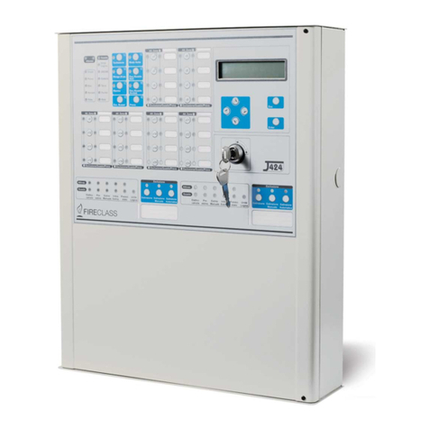
The FireClass Lite control panel dimensions and screw-
hole positions are as shown in Fig. 1.
The Field Interface Board use in the panel is the FIM801
Lite which is a partially populated version of the
FIM801 used in other FireClass addressable fire alarm
panels. (See Fig. 3).
Investigate Delay and Day/Night mode LED functions
are available.
For additional details, refer to ‘Operator Functions’ in
the FireClass Addressable Panels Product Information
and Design Application guide.
A 2.5 A power supply unit is fitted as standard.
It supports 7 Repeaters.
It has a 32 zone, LED display.
The Autoconfiguration feature restricts the number of
addressable devices on the loop to 125.
It is a stand-alone (non-networkable) version only.
2.2 FireClass Lite Express
It is a new template to support FireClass Lite. It is included
in the FireClass Express installer. The FireClass Lite Express
displays the below features:
The FireClass Lite Express supports 32 zones.
The FireClass Lite Express provides access to all 250
loop addresses, but only 125 may be used. This may
not include 125 devices if multiple addresses are used
per device.
It has a maximum power supply unit of 2.5 A.
It does not have any network support.
It has the same cause and effect mappings between the
input and output states as applicable to other panels.
FireClass Lite Express
FireClass Lite panels support only the Lite tem-
plate. Attempting to download any other tem-
plate will result in download failure and the mes-
sage is displayed as Incompatible Con-
figuration.

FireClass Fire detection system FireClass Panels 2.2 FireClass Lite Express
Product Information and Design Application Doc. version 1.0 7
Fig. 1: Overall and Fixing Dimensions – FireClass Lite
1–Knockouts Ø 20 mm (26x)
2–Knockout Ø 25 mm
3–Knockout Ø 20 mm
4–Knockouts
5–Mounting hole Ø 5.5 mm (3x)
130
370
40
40
290
40 40
245
325
162.5 162.5 126
3
1
2
5
5
54
4

2.2 FireClass Lite Express FireClass Fire detection system FireClass Panels
8 Product Information and Design Application Doc. version 1.0
The block schematic for the FireClass Lite panel is as shown in
Fig. 2.
Fig. 2: Typical Fire Detection and Alarm System using FireClass Lite Fire Alarm Control Panel
FIELD SUPPLY 24V
ALARM RELAY
FAULT RELAY
SOUNDER CIRCUIT 1
SOUNDER CIRCUIT 2
MAINS IN
+
-
24 V
BATTERY
FCNET
REMOTE
BUS +
-
REPEATER
SERIAL
PORT 1
PRINTER
SERIAL
AR+
AR- DET DET
DET*
IB CP DIM RIM
PLANT
DET*
SERIAL
PORT 2 CONFIGURATION
LIM800
CIM
EOL
CONTACT
EOL
AL+
AL-
KEY
DET - ADDRESSABLE DETECTOR
DET* - CONVENTIONAL DETECTOR
IB - ISOLATOR BASE
CP - CALLPOINT
DIM - DETECTOR INPUT MODULE
RIM - R E LAY INTE R FACE MODULE
CIM - CONTACT INPUT MODULE
LIM800 - LINE ISOLATOR

FireClass Fire detection system FireClass Panels 2.2 FireClass Lite Express
Product Information and Design Application Doc. version 1.0 9
Fig. 3: Differences between FIM801 and FIM801 Lite board indicated by cross marks
Components indicated by cross marks are not present on the FIM801 Lite board.
8
H
9H
01
LP
8
L
P
6LP
11H
01H
RL1 RL2
RL4
RL3
TNO
RF
REVOC
N
OR
F
FACE
FB2
RV1 RV 2
FB3
RL13
IC14
X3
IC22
X2
IC21
RL11
BPOO
L
MARGORP
A
P
O
OL
M
A
R
GO
R
P
IC6
4BF
8
H
9
H
0
1
L
P
8
L
P
6
L
P
1
1
H
0
1
H
RL
1
RL
2
RL
4
RL
3
T
N
O
R
F
R
E
V
O
V
V
C
N
O
R
F
F
A
F
A
A
CE
FB2
R
V1
R
R
R
V2
RR
FB
3
RL13
IC
C
C
C
C1
C1
C
C
C1
1
4
4
X
3
I
C
2
2
X
2
I
C
2
1
RL
11
B
P
O
O
L
M
A
R
G
O
R
P
A
P
O
O
L
M
A
R
G
O
R
P
I
C6
4
B
F
S1
PL9
C:\FC_Serv
_
LOOP
JP9
JP1
- INPUT +
/VISED
UNSUPER/
3MOC
KROWTEN
O/I
NO
IS
N
AP
X
E
2LP
RE
W
O
P
REMOTE BUS
N/O C N/C
ALARM
N/O C N/C
FAU LT ALARM I/P
SUPER/
INPUT
EMERGENCY
ALARM
- INPUT +
INPUTS
S/VISED
FAU LT
EARTH
ALARM FAU LT
2M
O
C
W/DOG I/O
1
M
OC
W/DOG
LOOP B
PL12
W/DOG
LOOP A
PL11
JP12
JP11
LOOP B
BL+ BL- BR+ BR-
Housing wi
t
Housing wi
t
JP10
JP2
JP3
JP4
JP6
JP7
JP8
JP5
SDR1 SDR2
PL13
AL+ AL- AR+ AR-
AR- AR+ AL- AL+
LOOP A
LOOP A
/VISED
POWER
H2
H1
H3
WDOG RESET
POWER
LOOP B
BR- BR+ BL- BL+
PL15
CPU board
fixed over
FIM800

2.2 FireClass Lite Express FireClass Fire detection system FireClass Panels
10 Product Information and Design Application Doc. version 1.0
2.2.1 FIM Connection Details
Fig. 4 shows the FIM801 Lite board connections.
All terminals accept solid/stranded conductors from 0.5 to
2.5 mm2.
Fig. 4: FIM801 Lite board connection (the labels match those on the FIM board)
1–Shown in the no alarm position
2–Shown in the no faults position
3–Spur sounder mode
4–Loop sounder mode
5–Note that sounders must be polarised and suppressed
SDR1
SDR2
+
+
-
-
2.7 kOhms
2.7 kOhms
N/O
C
N/C
N/O
C
N/C
FIM
ALARM
FAULT
34
5
5
1
2

FireClass Fire detection system FireClass Panels 2.3 Summary
Product Information and Design Application Doc. version 1.0 11
2.3 Summary
The FireClass Lite panel details are summarized as below:
2.4 Collected Specifications
2.4.1 Shock/Vibration
The shock vibration resistance meets EN54-2.
2.4.2 Dimensions
Table 3 shows the following dimensions for the FireClass
Lite panel.
2.4.3 Colour
For FireClass Lite panel, the colours are as follows:
Housing colour is RAL7035.
Control facia colour is Pantone Grey 431C.
2.4.4 Battery Details
The backup batteries are pairs of12 V SLA (sealed lead
acid) from Power Sonic.
The maximum internal resistance of the battery and its
associated circuitry is 0.35 Ohms.
Table 5 shows the maximum PSE loads.
2.4.5 PSU
Table 6 shows the mains requirements.
Values are shown as default/maximum
Panel Number of
addressable
circuits
(loops)
Points *
per loop
Points
per CIE
Zones per
loop
Zones per
panel
Zone
LEDs
Batteries
FireClass Lite 1 125 125 32/240 32/240 32 2 x 12 Ah
Table 2: Numbers of loops, zones and points
* Points can be any combination of detectors, call-points, addressable ancillaries and addressable sounders.
Panel Height (mm) Width (mm) Depth (mm)* Weight (Kg)** Input Current***
FireClass Lite 370 325 126 7 0.9 A
Table 3: Dimensions
* To the wall add 4_mm – see the dimension drawings
** Excluding batteries
*** With no power supplied to optional ancillaries
Panel Battery
Code
Capacity
(Ah)
Weight
(Kg)
FireClass Lite PS-12120 12 3.6
Table 4: Battery Details
Panel Imaxa: Ipse Imaxb: Ipse
FireClass Lite 1.9 A 2.5 A
Table 5: Maximum PSE Loads
Item Unit Type Value
Current FireClass Lite 2.5 A and
1xPMM800
0.9 A
Voltage FireClass Lite 2.5 A and
1xPMM800
230 V
50/60 Hz
Table 6: Mains Power Requirements
Reference Document
For additional details on Addressable loop
Cabling considerations, Wiring configurations
Termination and Loop loading calculations, refer
to FireClass Designer Help file.

2.5 Component Module Descriptions FireClass Fire detection system FireClass Panels
12 Product Information and Design Application Doc. version 1.0
2.4.6 PMM800 Power Monitoring
Module
Input
– The 230 V AC mains supply is connected to the
input of the power supply unit (BAQ60T24). The
28.6 VDC output from the power supply unit is fed to
the input of the PMM800.
Output
Table 7 shows the 3 DC output rails voltage ranges:
The PMM800 provides four 24 V outputs. Each output is
fitted with fuse. These are F1AL 250VAC 20x5mm fast
blow glass fuses.
There is a battery fuse fitted. This is a T8AH 250VAC
20x5 mm ceramic anti-surge fuse.
2.4.7 Siting Considerations
The fastenings are not included in the kit, so they will need
to be externally sourced. When specifying the fastenings
(such as the screw size), take into account the type of wall
and the weight of the assembled housing. The size of the
batteries will have a large bearing on the weight of the units
(see 2.4 “Collected Specifications” on page 11).
The control panel is designed for wall mounting. Typically
screws and rawlplugs in drilled holes will be used. The
screw hole positions are shown in Fig. 1: “Overall and Fixing
Dimensions – FireClass Lite” on page 7 .
2.4.8 Environmental Stipulations
The control panel is not weatherproof. Check that the loca-
tion is indoors, dry and free from excessive dust. Also check
that location fulfils the temperature and humidity stipula-
tions shown in Table 8: “Temperature and Humidity Stipu-
lations”.
2.4.9 EMC
Product family standard EN50130-4 in respect of Con-
ducted Disturbances, Radiated Immunity, Electrostatic Dis-
charge, Fast Transients and Slow High Energy
EN 61000-6-3 for Emissions.
2.5 Component Module
Descriptions
The following sections detail the standard modules fitted to
an FireClass Lite control panel or repeater.
2.5.1 Central Processing Unit
The Central Processing Unit (CPU800 board) contains the
main processor and memory. It is mounted to the FIM801
Lite board.
2.5.2 Field Interface Module (FIM)
The FIM801 Lite provides all the inputs and outputs of the
control panel. Refer to Fig 4 for FIM Board connections.
Rail Voltage Range
28 VVout(max)=28.6 V (Tamb=—10C, Iout=0).
Vout(min)=20 V(Tamb=50 C), Iout=2.5 A
(BAQ60T24).
Output ripple: 150 mV p-p maximum at maxi-
mum load
BAQ60T24: 0-2.5 A, Imaxb=2.5 A,
Imaxa=1.9 A (12A-h Battery charging at C/20
rate)
Maximum current available on the 28 V rail
(I(28)) in either condition, may be calculated from
the following formula:-
I(28)=I(max)-0.211*I(5)-1.568*I(40)
Where:
I(max)=Imaxa or Imaxb i.e. whichever is being
considered
I(5)=Current drawn from 5 V rail
I(40)=Current drawn from 40 V rail
5 V Output voltage: 4.85 V-5.25 V @ 50m A to
1.5 A. Minimum load=50 mA.
Output ripple: 150 mV p-p maximum.
40 V Output voltage: 39.75 V-40.2 V @ 0 to 1.25 A.
Output ripple: <40 mV p-p 1-10 KHz acceptable
level increasing 6 dB/octave either side.
Table 7: PMM800 Output Rail Voltage Ranges
Parameter Value
Operating Temperature -5°C to +40°C
Storage Temperature -20°C to +70°C
Operating and storage
maximum Relative
Humidity
95% RH non-condensing
Table 8: Temperature and Humidity Stipulations

FireClass Fire detection system FireClass Panels 2.6 Unavailable Features for FireClass Lite
Product Information and Design Application Doc. version 1.0 13
2.5.3 Display and Control Module
The Display and Control Module (DCM) contains the dis-
play, indicators and keys, that the operator uses to interact
with the panel. The DCM for FireClass Lite is shown in
Fig. 5.
2.6 Unavailable Features for
FireClass Lite
The following features are not available for FireClass Lite
panels:
IC field upgrade of the I/O Processor cannot be done.
IC field repair of the RS232 is not possible.
Some of the front cover connectors are not present in
the FIM801 Lite board.
Loop expansion is not possible.
Network connection is not possible.
The Input/Output Bus expansion is not possible.
The Supervised and Unsupervised inputs are not sup-
ported.
The Emergency Alarm I/P is not provided.
2.7 Ordering Information
The stock code number for FireClass Lite is as follows:
Fig. 5: DCM-FireClass Lite
Reference Document
For additional details, refer to ‘Component Mod-
ule Description’ in the FireClass Addressable
Panels Product Information and Design Applica-
tion guide.
Panel Ordering Number
FireClass Lite1 loop -
125device, 32 zone panel
557.200.709
Table 9: Ordering Number

Company stamp
Further information about FIRECLASS
can be found on the Internet at
www.fireclass.co.uk
United Kingdom
FIRECLASS
Hillcrest Business Park
Cinder Bank
Dudley
West Midlands
DY2 9AP
United Kingdom
www.fireclass.co.uk
120.515.093_FC-Lite-A, doc. version 1 , 25. Apr 2012. Subject to change without notice.
Table of contents
Other FireClass Fire Alarm manuals

FireClass
FireClass Precept EN13 Guide

FireClass
FireClass DUO-CEL User guide

FireClass
FireClass 5B User manual

FireClass
FireClass J400 User manual

FireClass
FireClass Precept EN Panel Guide

FireClass
FireClass FC503 User manual

FireClass
FireClass FC430SB User manual

FireClass
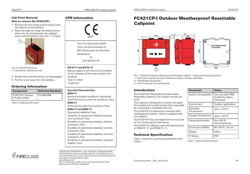
FireClass FC421CP-I Manual

FireClass
FireClass Prescient III Guide

FireClass
FireClass FC420CP User manual