manuals.online logo
Brands
  1. Home
  2. •
  3. Brands
  4. •
  5. Firstech
  6. •
  7. Automobile Accessories
  8. •
  9. Firstech FTI-NSP2 Operating instructions

Firstech FTI-NSP2 Operating instructions

FTI-NSP2 Type 3 - Vehicle Coverage & Preparation Notes
Make Model Year Install I/O Changes
DL-NI9
Nissan
Nissan
Nissan
Nissan
Nissan
Nissan
Nissan
Quashqai STD Key
Quashqai STD Key
Rogue Sport STD Key
Rogue Sport STD Key
Rogue STD Key
Rogue STD Key
Rogue STD Key
2017-18
2019
2017-18
2019
2014-16
2017
2018-19
Type 3
Type 3
Type 3
Type 3
Type 3
Type 3
Type 3
CAN Lights BCM POC1
Green White/BluePark / Auto
Hey! Read this stuff before you start the installation...
Firmware:
Covered vehicles use BLADE-AL(DL)-NI9, flash module and update the controller firmware before installing.
CAN:
CAN data is acquired from the BCM using the BCM CAN connector cable, connect, secure against main harness body, and
route securely.
POC1:
Visual status confirmations and diagnostic information are provided by hazard light connections in the harness assembly, POC1
must be configured for either Hazard1 (POC option #30 (momentary switch) or Hazard2 (POC option #23 (latching switch).
Vehicle Damage Warning:
Caution should be taken to avoid mixing up the BCM connectors, vehicle damage will result if the connectors are positioned
improperly. It is advised that you make the BCM connections one at a time, confirming that each T-harness connection is at
the correct BCM position before proceeding to the next connection, attempting to program, or attempting to remote start.
CM Unlock Configuration: Covered vehicles require configuring the controller unlock output to double-pulse unlock.
Set feature option 1-04 to setting 2 (unlock).
Okay, now get to work...
BCM
BCM
BCM
BCM
BCM
BCM
BCM
CM I/O
CM I/O
CM I/O
CM I/O
CM I/O
CM I/O
CM I/O
DSD
DSD
DSD
DSD
DSD
DSD
DSD
Hazard1/2
Hazard1/2
Hazard1/2
Hazard1/2
Hazard1/2
Hazard1/2
Hazard1/2
CM-900
CM-900S/900AS
CM7X00
CM7000/7200 Cut loop for A/T
CM900AS/900S Jumper
SUPPORT - 1(888) 820-3690, EXT. 203
DEREK ZOOLANDER
Est. 2001
CENTER KIDS
WHO CAN’T READ GOOD
A
N
D
W
H
O
W
A
N
N
A
L
E
A
R
N
T
O
D
O
O
T
H
E
R
S
T
U
F
F
G
O
O
D
T
O
O
I
I
I
I
I
I
I
I
I
I
I
I
I
I
I
I
I
I
I
I
I
I
I
I
I
I
I
I
I
I
I
I
I
I
I
I
I
I
I
I
I
I
I
I
I
I
I
I
I
I
I
I
I
I
I
I
I
I
I
I
I
I
I
I
I
I
I
I
I
I
I
I
I
I
I
I
I
I
I
I
I
I
I
I
I
I
I
I
I
I
I
I
I
I
I
I
I
I
I
I
I
I
I
I
I
I
I
I
I
I
I
I
I
I
I
I
I
I
I
I
I
I
I
I
I
I
for
But wait! First check your harness...
The initial production release of the FTI-NSP2 harness has an issue
where the green/white POC1 circuit is incorrectlypositioned in the
CM7 I/O connector. This issue affects only the gray 20-pin CM7 I/O
connector illustrated on page 3 of this guide. Please confirm whether
you are installing one of the affected harnesses by comparing the
CM7 I/O connector to the illustration on page 3. If the green/white
wire is as highlighted in Fig.1, proceed with the modification and follow
the POC assignments listed on page 3.
CM7
READ
THIS
*Not required
A B C D E
A
B
C
D
Confirm that NI8 cable connection (BLACK 14-pin male to WHITE 14-PIN female) is selected
prior to making connections to vehicle. Secure unused NI3 connector to ensure against short circuits.
Intermediate NI8/9 BCM CAN connector, secure to main harness body and route toward BCM along
with main harness.
Programmable ACC/IGN output from CN1 BLUE wire, not used in NI8 applications, either cut
short or fold back and insulate using tape. Secure to harness body to ensure against short circuits.
HOOD, SIREN, and HORN connections from CM I/O connector, use as needed
LED Error Codes
Module LED flashing RED during programming
1
2
SUPPORT - 1(888) 820-3690, EXT. 203
FTI-NSP2 Type 3
Module Programming
FTI-NSP2 Type 3 - Installation Notes & Wiring Diagram
1
16
D
HORN
HOOD
SIREN
A
B
NI8/9
NI3
C
CM900S CM900AS CM7 I/O PWR
BLADE Lock
14
68
16
4
OBD-II Connector
BCM
1
2
1x - No CAN data, confirm connectors, check voltage
2x - Waiting for IGN ON
3x - No key detected, confirm NI8/9 harness configuration
4x - Detecting NI3 configuration, confirm connections
5x - Immobilizer sequence not initiating, wake vehicle
6x - Immobilizer sequence not initiating, reset module, wake
vehicle and retry programming, if issue persists, restart
7x - Klon data does not match, reset and restart procedure
8x - Harness error
Step 1 - Activate IGN
Step 2 - LED should go red, blue, red
Step 3 - Deactivate IGN
Step 4 - Activate IGN, if LED flashes rapidly
disconnect and return to computer for
extended programming*, if LED goes solid
blue, programming complete
Step 5 - *After extended programming, activate
IGN, solid blue LED, programming complete
BlackBlueGreen
See Vehicle Damage Warning on previous page.
BLADE
CM7
CM900S
CM900AS
NI8/9 BCM
PROGRAMMABLE
ACC/IGN
White
POC1 - must be
set for HAZARD1/2
POC4 - must be
set for HORN
FTI-NSP2 Harness Bulletin - Mis-wired POC1 (parking lights) SUPPORT - 1(888) 820-3690, EXT. 203
DEREK ZOOLANDER
Est. 2001
CENTER KIDS
WHO CAN’T READ GOOD
A
N
D
W
H
O
W
A
N
N
A
L
E
A
R
N
T
O
D
O
O
T
H
E
R
S
T
U
F
F
G
O
O
D
T
O
O
I
I
I
I
I
I
I
I
I
I
I
I
I
I
I
I
I
I
I
I
I
I
I
I
I
I
I
I
I
I
I
I
I
I
I
I
I
I
I
I
I
I
I
I
I
I
I
I
I
I
I
I
I
I
I
I
I
I
I
I
I
I
I
I
I
I
I
I
I
I
I
I
I
I
I
I
I
I
I
I
I
I
I
I
I
I
I
I
I
I
I
I
I
I
I
I
I
I
I
I
I
I
I
I
I
I
I
I
I
I
I
I
I
I
I
I
I
I
I
I
I
I
I
I
I
I
for
Overview: The initial production release of the FTI-NSP2 harness has an issue where the POC1 circuit is incorrectly
positioned in the CM7 I/O connector. This issue affects only the gray 20-pin CM7 I/O connector illustrated below in figure 1.
Issue: The green/white parking light circuit is positioned in pin position #17, the fixed light output where the green/white
wire is typically placed for parking lights, but the harness solution uses the vehicle hazard lights instead, the result when
used as supplied is an erratic light display.
Correction:
1.) Use a pick tool to depress the locking tab on the terminal connector of the green/white wire
2.) Remove wire and prepare to reposition
3.) Once removed, reposition the locking tab by using a razor knife to lift the tab into a usable position
4.) With locking tab repositioned, relocate to pin position #1 (top right position as illustrated)
5.) Push the terminal connector into the I/O connector housing until the locking tab clicks into place and the wire is secure
6.) Correction complete, you may now complete the installation, but remember to configure POC1 for Hazards (setting #30)
Figure 1: Incorrect placement Figure 2: Corrected placement
POC1 - must be
set for HAZARD1/2
POC4 - must be
set for HORN

Other Firstech Automobile Accessories manuals

Firstech BLADE Series User manual

Firstech

Firstech BLADE Series User manual
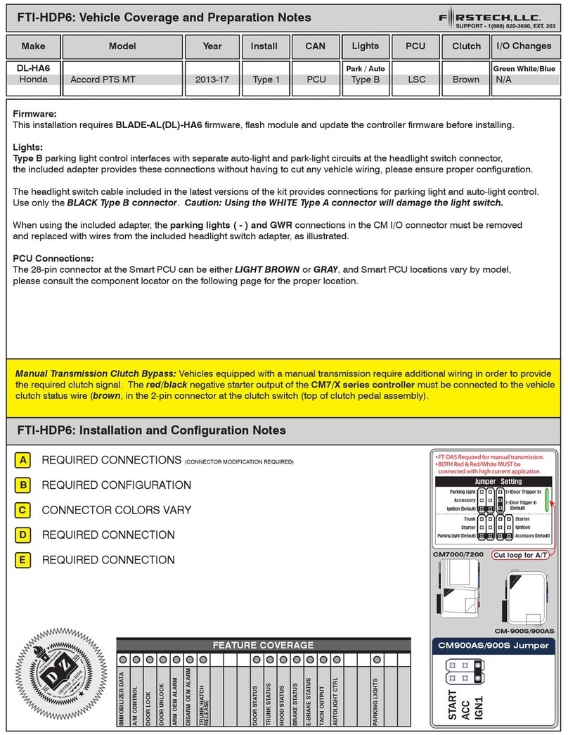
Firstech FTI-FDK1 1A3 User manual

Firstech

Firstech FTI-FDK1 1A3 User manual

Firstech BLADE Series User manual

Firstech

Firstech BLADE Series User manual

Firstech FTI-FDK1- Type 2A1 Operating instructions

Firstech

Firstech FTI-FDK1- Type 2A1 Operating instructions

Firstech 1WS2R-AF Technical manual

Firstech

Firstech 1WS2R-AF Technical manual

Firstech FTI-HDP6 Operating instructions
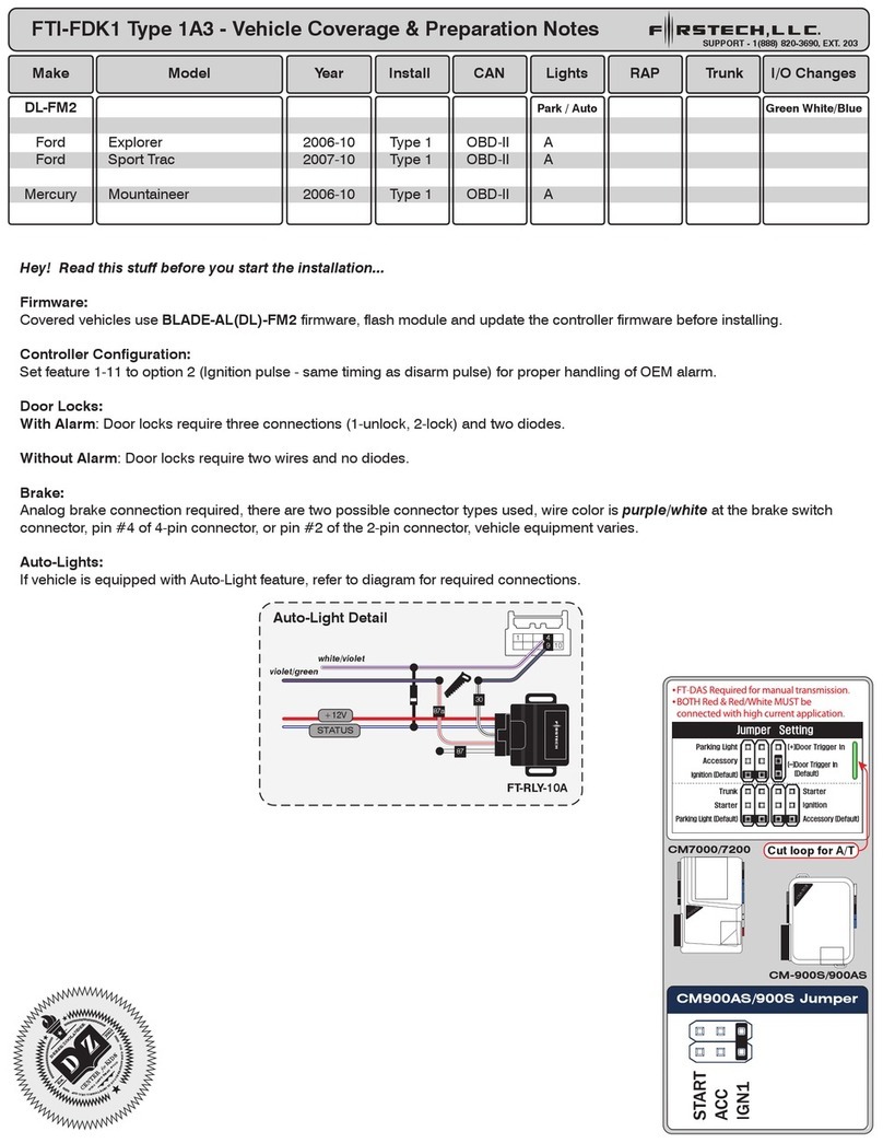
Firstech

Firstech FTI-HDP6 Operating instructions

Firstech RF-AR1WG14R-FM Technical manual

Firstech

Firstech RF-AR1WG14R-FM Technical manual

Firstech FTI-FDK1 User manual

Firstech

Firstech FTI-FDK1 User manual

Firstech DASII-2021 Operating instructions

Firstech

Firstech DASII-2021 Operating instructions

Firstech ADS FT-DC3-LC User manual

Firstech

Firstech ADS FT-DC3-LC User manual

Firstech 2WT13R-SF User manual

Firstech

Firstech 2WT13R-SF User manual

Firstech FLEX 2 User manual

Firstech

Firstech FLEX 2 User manual

Firstech Compustar FMX RF-2WG15R-FM User manual

Firstech

Firstech Compustar FMX RF-2WG15R-FM User manual

Firstech FTI-HDP7 User manual

Firstech

Firstech FTI-HDP7 User manual

Firstech 2WQ9R-FM User manual

Firstech

Firstech 2WQ9R-FM User manual

Firstech FTI-GMT3 User manual

Firstech

Firstech FTI-GMT3 User manual

Popular Automobile Accessories manuals by other brands
CoverCraft Grommet Installation

CoverCraft

CoverCraft Grommet Installation

Over Armour Offroad CA-MAVERICKX3-4-TC01 Instructions for Installation and Care

Over Armour Offroad

Over Armour Offroad CA-MAVERICKX3-4-TC01 Instructions for Installation and Care

Smittybilt 2783 owner's manual

Smittybilt

Smittybilt 2783 owner's manual

ACEFAST D1 user manual

ACEFAST

ACEFAST D1 user manual

Team Tech Offroad TACOMA HOOD STRUT Kit Installation

Team Tech Offroad

Team Tech Offroad TACOMA HOOD STRUT Kit Installation

Detroit Speed Selecta-Speed 121633 manual

Detroit Speed

Detroit Speed Selecta-Speed 121633 manual

Hama 00200015 operating instructions

Hama

Hama 00200015 operating instructions

SCHROTH Interior Net Installation and use guideline

SCHROTH

SCHROTH Interior Net Installation and use guideline

Uni-bond E-336A installation manual

Uni-bond

Uni-bond E-336A installation manual

Pyle PLCM4235 user manual

Pyle

Pyle PLCM4235 user manual

Minimizer LONG HAUL Series Service manual

Minimizer

Minimizer LONG HAUL Series Service manual

Tactik 12011.010 Series installation manual

Tactik

Tactik 12011.010 Series installation manual

Car Solutions QVI-LVTX-1CH-V7 user manual

Car Solutions

Car Solutions QVI-LVTX-1CH-V7 user manual

Tyger T1 manual

Tyger

Tyger T1 manual

Sentaz Tactile Car Seat quick guide

Sentaz

Sentaz Tactile Car Seat quick guide

ICI Alumilite Steps 840121412920 Direction for Installation and Use

ICI

ICI Alumilite Steps 840121412920 Direction for Installation and Use

Keith Running Floor II Metric installation manual

Keith

Keith Running Floor II Metric installation manual

Canyon C-02 quick guide

Canyon

Canyon C-02 quick guide

manuals.online logo
manuals.online logoBrands
  • About & Mission
  • Contact us
  • Privacy Policy
  • Terms and Conditions

Copyright 2025 Manuals.Online. All Rights Reserved.