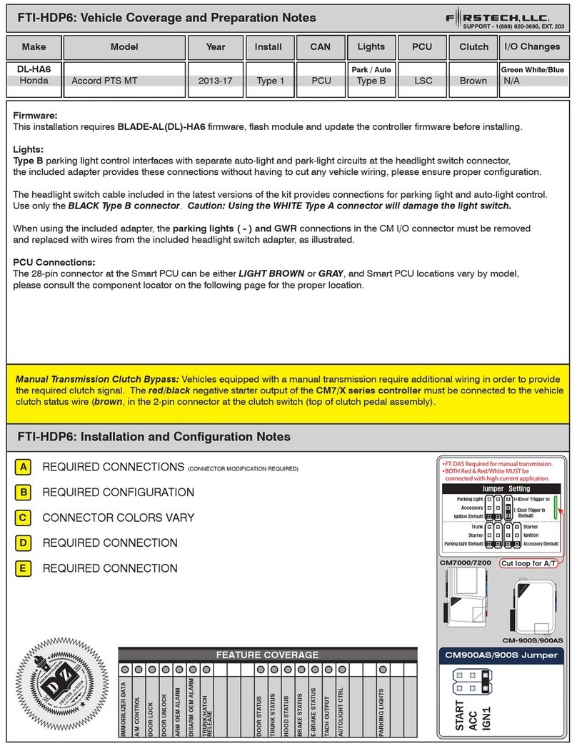
A B C D E
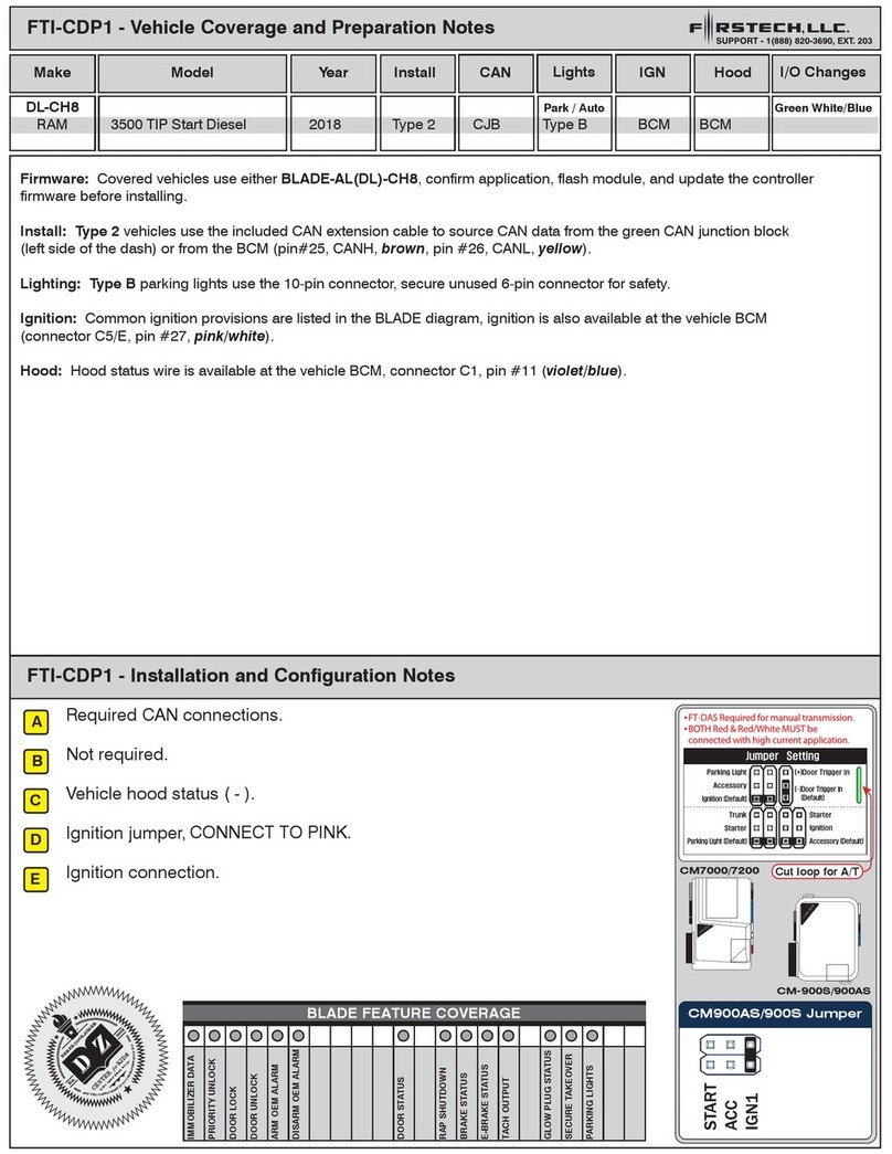
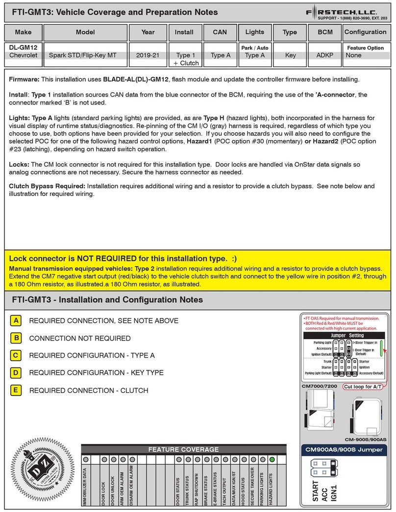
A
B
C
D
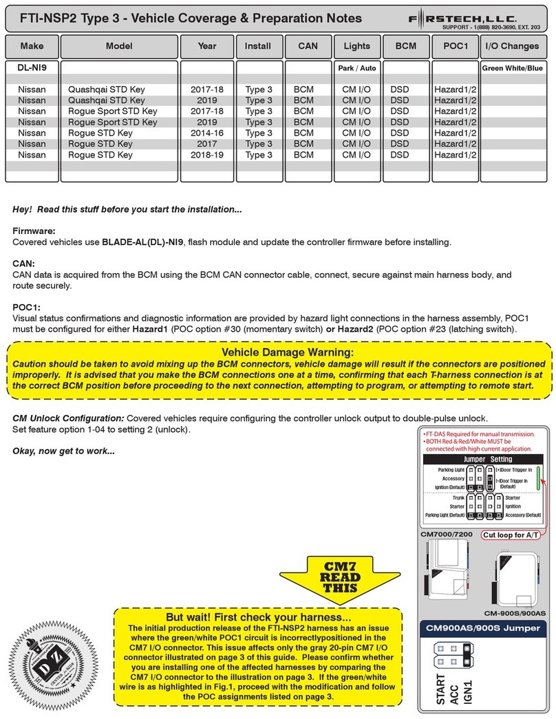
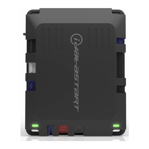
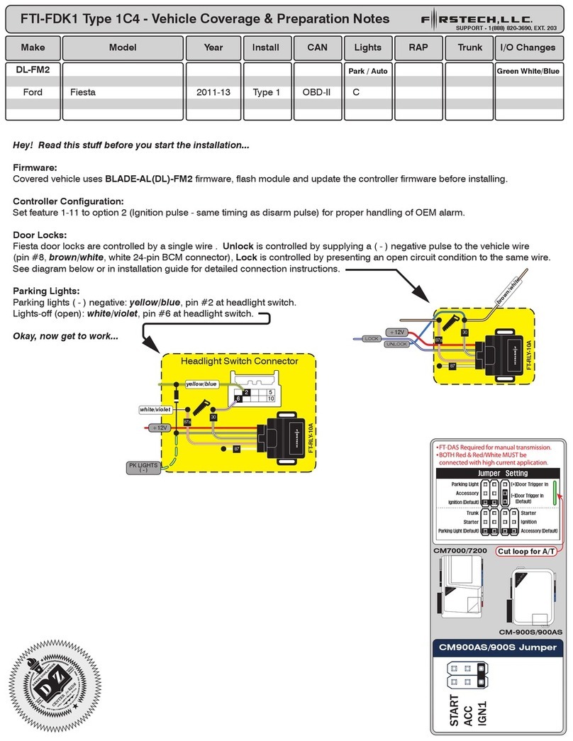
DL-FM3 TX loop: DO NOT cut loop until module has been programmed to vehicle, CUT loop after
programming has been completed, before first remote start attempt
Immobilizer disable jumper: DO NOT connect jumper unless vehicle is confirmed not equipped with
an immobilizer system, if not equipped, connect jumper before programming attempt
Rear hatch release: ( - ) at black 26-pin BCM connector (pin #23, brown), also available at hatch
release switch 6-pin connector (pin #6, gray or brown), or 8-pin connector (pin #7, gray/yellow)
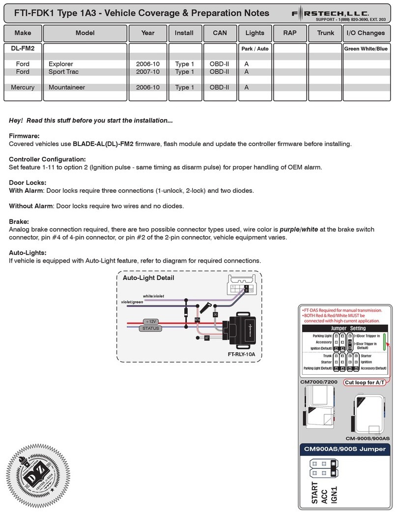
+ Parking lights: If vehicle is not equipped with auto-lights, + parking lights are available at the gray
10-pin BCM connector (pin #6, yellow/blue). If equipped with auto-lights, see Auto-light detail 1
2
3
4 5
SUPPORT - 1(888) 820-3690, EXT. 203
FTI-FDK1 Type 2A1
13
14
16 8 9
26
10
1
6
5
1
46
3
23
BCM
Hatch Release
Black
Gray
3
4
FTI-FDK1 Type 2A1 - Installation Notes & Wiring Diagram
Module Programming Procedure
Step 1 - Key #1 in activate IGN, if LED goes blue, you’re done
if LED goes red, wait until flashes blue then remove key,
wait until LED is off, then activate IGN with key #1, when
LED is red, remove key and go to step 2.
Step 2 - Insert key #2, activate IGN, when LED is red, remove key
then remote start vehicle, blue/done.
**See BLADE guide for more detailed instructions
LED Programming Error Codes
Module LED flashing RED during programming
1x - CAN error, check wiring
2x - VIN error, check CAN wiring
3x - Wrong firmware, confirm firmware flashed
4x - VIN error, vehicle not identified, contact support
5x - Immobilizer learn error, check RX/TX wiring
**Rapid red flash - RX/TX issue, reverse wires, confirm
2 different keys, confirm vehicle immobilizer is operational
9x - Key in cylinder, remove and proceed
1
2
PWR
BLADE
Lock
1
16
RAP
LOCK/UNLOCK
TRUNK RELEASE
OBD-II Connector
Ignition switch
blue/black
blue
violet
white/black
white/red
DRIVER DOOR PIN
(+) PARKING LIGHTS green/white
violet/white
blue/green
yellow/violet
yellow/blue
brown
gray
A
B
C
D
Alternate connections
at hatch release
DO NOT FEED
until module
programming is
complete
C
10
14
87a
87
30
STATUS
+12V
white/violet
violet/green
FT-RLY-10A
Auto-Light Detail
6
5
4
178
gray/yellow
*brown
or
