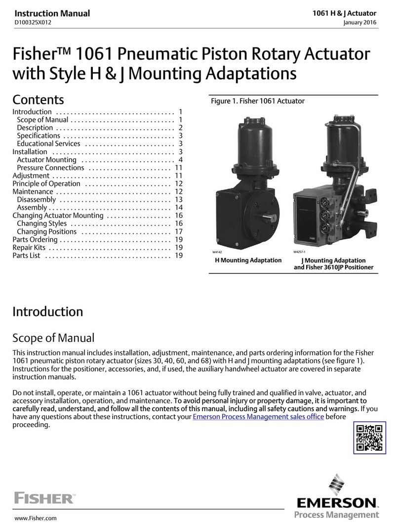
Type 1066 With H Mounting
Figure 4. Center of
Gravity Dimensions
operated equipment shaft, refer to the
changing positions procedure in the
Changlng Actuator Mounting section. This
procedure describes how the output shafi
can be repositioned to accommodate the
operated equipment shaft.
2. Attach an appropriate mounting bracket (not
provided) against the travel indicator scale(key21) inthe
desired orientation with the cap screws (key 20). See
figure 3 for mounting dimensions on the travel indicator
scale. Tighten the cap screws to 18 foot-pounds (25
N-m) for size 20 actuators and to 75 foot-pounds (102
Nom) for size 75 actuators.
3. Slide the actuator (with the user-provided mounting
bracket attached) into the user-provided coupling on the
operated shaft. Then, secure theactuatorto the operated
equipment in the desired mounting position with appre
priate fasteners, such as mounting cap screws. See
figure 3 for output shaft dimensions.
4. If necessary perform the adjustment procedure
before proceeding totheloadingconnectionsprocedure.
Loading Connections
1. Type 1066 actuators should have either a loading
solenoid, a four-way switching valve, or two threeway
switching valves connected tothe i/4-inch NPTpressure
connections located at the top and bottom of the actuator
cylinder.
2. Connecteither1/4-inch(6.4mm) or3/6-inch(9.5 mm)
tubing between the actuator pressure connections and a
controlling instrument Keep the length of tubing asshort
aspossibleto avoid transmission laginthe control signal.
3. When the actuator is completely installed and
connected to the instrument, check the actuator for
correct action (air-teopen or air-toclose) to match the
controlling instrument. For successful operation, the
piston rod (key 5) and equipment operating shaft must
move freely in response to loading pressure changes on
the piston (key 3).
Adjustment
Key numbers referenced in this section are shown in
figure 6.
Avoid personal injury or property damage
from a sudden release ot process pressure
or uncontrolled process fluid. Before
starting adjustment:
l
Isolate the valve or other operated
equipment from the process,
l
Release process pressure, and
l
Vent the actuator loading pressure.
TheTypel066 actuatorisfactorysetforafull90degrees
of operated shaft rotation unless otherwise specified by
thecustomer. Adjustmentsmay bemadeafterinstallation
by looseningthe self-sealing nuts(key37) and turning the
set screws(key 12).Top andbottom piston position limits
are set with the upper andlower setscrews, respectively.
If rotation of either set screw (key 12) seems difficult,
apply Lubriplate MAG-II11lubricant or equivalent (key35)
to the threads of each set screw as shown in figure 6.
4
