flamco Vacumat Eco Series User manual

TemplateA4_v20130506
Vacumat Eco®
NOR
ESP
POL HUN
ENG DEU NLD FRA ITA DAN
SWE FIN CES SLK
RUS TUR
www.amcogroup.com/manuals
TemplateA4_v20130506
2
BE Flamco Belux
Monnikenwerve 187 /1
B -8000 Brugge
+32 50 31 67 16 info@amco.be
CH Flamco AG
Fännring 1
6403 Küssnacht
+41 41 854 30 50 info@amco.ch
CZ Flamco CZ
Evropská 423/178
160 00 Praha 6
+420 602 200 569 info@amco.cz
DE FlamcoGmbH
Steinbrink3
42555Velbert
+49 2052 887 04 info@amco.de
DK Flamco
Tonsbakken16-18
DK-2740Skovlunde
+45 44 94 02 07 info@amco.dk
EE Flamco Baltic
Löötsa 4
114 15 Tallin
+372 56 88 38 38 info@amco.ee
FI FlamcoFinland
Ritakuja1
01740 Vantaa
+358 10 320 99 90 info@amco.
FR Flamcos.a.r.l.
BP 77173
95056CERGY-PONTOISEcedex
+33 1 34 21 91 91 info@amco.fr
HU FlamcoKft.
H-2040Budaörs,Gyáru.2
H-2058Budaörs,Pf.73
+36 23 88 09 81 info@amco.hu
NL FlamcoB.V.
Postbus502
3750 GM Bunschoten
+31 33 299 75 00 support@amco.nl
PL FlamcoSp.zo.o.
ul.Akacjowa4
62-002SuchyLas
+48 616 5659 55 info@amco.pl
SE Flamco Sverige
Kungsgatan 14
54131Skövde
+46 500 42 89 95 vvs@amco.se
UAE FlamcoMiddleEast
P.O.Box262636
JebelAli,Dubai
+971 4 881 95 40 info@amco-gulf.com
UK FlamcoLimited
WashwayLane-StHelens
MerseysideWA106PB
+44 1744 74 47 44 info@amco.co.uk

TemplateA4_v20130506
3
Vacumat Eco
ENG Installationandoperatinginstructions
Translation of the original operating instructions ____________________________________________________________________________________________ 5
DEU Montage-undBetriebsanleitung
Orginalbetriebsanleitung___________________________________________________________________________________________________________________________ 29
NLD Montageengebruikshandleiding
Vertalingvandeoorspronkelijkegebruiksaanwijzing_______________________________________________________________________________________ 53
FRA Installationetmoded’emploi
Traductiondelanoticed’utilisationoriginale_________________________________________________________________________________________________ 77
ESP Instruccionesdeinstalaciónyfuncionamiento
Traduccióndelasinstruccionesdefuncionamientooriginales__________________________________________________________________________ 101
ITA Istruzionid’installazioneed’impiego
Traduzionedelleistruzionioperativeoriginali ________________________________________________________________________________________________ 125
DAN Monterings-ogdriftsvejledning
Oversættelseafdenoriginalebetjeningsvejledning ________________________________________________________________________________________ 149
NOR Installasjons-ogbruksanvisning
Trykksikring,aktivavgassing,påfylling_________________________________________________________________________________________________________ 173
SWE Instruktionerförinstallationochdrift
Översättning av originalinstruktionerna ________________________________________________________________________________________________________ 197
FIN Asennus-jakäyttöohjeet
Alkuperäistenkäyttöohjeidenkäännös_________________________________________________________________________________________________________ 221
POL Instrukcjamontażuiobsługi
Tłumaczenieoryginalnejinstrukcjiobsługi ____________________________________________________________________________________________________ 245
HUN Telepítésiésüzemeltetésiútmutató
Azeredetiüzemeltetésiútmutatófordítása ___________________________________________________________________________________________________ 269
CES Návodkinstalaciaobsluze
Překladoriginálníchprovozníchpokynů_______________________________________________________________________________________________________ 293
SLK Návodnamontážaobsluhu
Prekladpôvodnéhonávodunaobsluhu _______________________________________________________________________________________________________ 317
RUS Инструкции по установке и эксплуатации
Перевод оригинального руководства по эксплуатации _______________________________________________________________________________ 341
TUR Montajvekullanmakılavuzu
Orijinalçalışmatalimatlarınınçevirisi ___________________________________________________________________________________________________________ 365

TemplateA4_v20130506
4

TemplateA4_v20130506
ENG
5
English (ENG) Instruction and installation manual
Content
1. Liability ................................................................................................................................................................................................................. 6
2. Warranty ............................................................................................................................................................................................................... 6
3. Copyright ............................................................................................................................................................................................................. 6
4. General safety instructions ................................................................................................................................................................................ 6
Purposeanduseofthismanual........................................................................................................................................................................... 6
Qualicationsrequired,assumptions.................................................................................................................................................................... 6
Staffqualication.................................................................................................................................................................................................. 7
Intendeduse......................................................................................................................................................................................................... 7
Incominggoods.................................................................................................................................................................................................... 7
Transportation,storageandunpacking................................................................................................................................................................ 7
Operations room ................................................................................................................................................................................................... 7
Noisereduction..................................................................................................................................................................................................... 8
Emergencystop/Emergency-off......................................................................................................................................................................... 8
Personalprotectiveequipment(PPE)................................................................................................................................................................... 8
Exceedingpermittedpressure/temperaturelevels............................................................................................................................................. 8
Systemwater........................................................................................................................................................................................................ 8
Safeguards............................................................................................................................................................................................................ 8
External forces ...................................................................................................................................................................................................... 9
Inspectionbeforecommissioningandre-inspection............................................................................................................................................ 9
Operating insurance inspections .......................................................................................................................................................................... 9
Electricalequipmentinspections,routineinspection........................................................................................................................................... 9
Maintenanceandrepairs....................................................................................................................................................................................... 9
Obviousmisuse..................................................................................................................................................................................................... 9
Residualhazards................................................................................................................................................................................................... 10
Warningsymbolsinthismanual........................................................................................................................................................................... 10
5. Product description ............................................................................................................................................................................................ 10
Additionaldocumentation..................................................................................................................................................................................... 10
Plantlayout........................................................................................................................................................................................................... 10
Components/equipment..................................................................................................................................................................................... 11
Modeofoperation................................................................................................................................................................................................. 12
Marking ................................................................................................................................................................................................................. 14
6. Assembly .............................................................................................................................................................................................................. 16
Installing,leveling,bolting..................................................................................................................................................................................... 16
Connecting the pipework ...................................................................................................................................................................................... 16
Connectingtheelectricalsupply........................................................................................................................................................................... 16
7. Commissioning .................................................................................................................................................................................................... 16
Commissioning ..................................................................................................................................................................................................... 16
Settings / control actions ...................................................................................................................................................................................... 17
Recommissioning .................................................................................................................................................................................................. 17
Explanations relating to the SPC m1 control menu .............................................................................................................................................. 17
8. Maintenance ........................................................................................................................................................................................................ 19
Malfunction list / error messages .......................................................................................................................................................................... 19
Appendix 1. Technical data, general specications ................................................................................................................................................. 21
Ambientconditions....................................................................................................................................................................................................... 21
Installation examples ..................................................................................................................................................................................................... 21
Example of a unit / pipeline integration ......................................................................................................................................................................... 22
Minimumdistances:clearanceforserviceandrepair................................................................................................................................................... 22
Appendix 2. Technical Data, specications .............................................................................................................................................................. 23
Appendix 3. Menu structure of the SPC m1 - diagram ............................................................................................................................................ 24
Appendix 4. Terminal diagram .................................................................................................................................................................................... 25
Appendix 5. Optional accessories and their integration .......................................................................................................................................... 26
Appendix 6. Declaration of Conformity ..................................................................................................................................................................... 27

TemplateA4_v20130506
6
1. Liability
Alltechnicalinformation,dataandinstructionscontainedintheseoperatinginstructionsforpracticaloperationsandthosetobe
performedarecorrectatthetimeofgoingtopress.Thisinformationistheresultofourcurrentndingsandexperiencetothebestof
ourknowledge.WereservetherighttomaketechnicalchangessubjecttothefuturedevelopmentoftheFlamcoproductreferredto
inthispublication.Hencenorightsmaybederivedfromtechnicaldata,descriptionsandillustrations.Technicalpictures,drawings
andgraphsdonotnecessarilycorrespondtotheactualassembliesorpartsasdelivered.Drawingsandpicturesarenottoscaleand
containsymbolsforsimplication.
2. Warranty
WarrantyspecicationscanbefoundinourGeneralTermsandConditionsanddonotformpartofthismanual.
3. Copyright
Thismanualmustbeusedcondentially.Itmaybecirculatedamongauthorisedpersonnelonly.Itmustnotbegiventothirdparties.
Alldocumentationisprotectedbycopyright.Distributionorotherformsofreproductionofdocuments,evenextracts,exploitation
ornoticationofthecontentshereofisnotpermitted,wherenototherwisespecied.Infringementsareliabletoprosecutionand
paymentofcompensation.Wereservetherighttoexerciseallintellectualpropertyrights.
4. General safety instructions
Disregardorlackofattentiontotheinformationandmeasuresinthismanualmayposeahazardtopeople,animals,theenvironment
andtangibleassets.Failuretoobservethesafetyregulationsandtheneglectofothersafetymeasuresmayleadtothelossofliability
fordamagesintheeventofdamageorloss.
Denitions
• Operator:Anaturalpersonorlegalentitywhoistheowneroftheproductandusestheaforementionedproduct,orisnominatedto
useit,underthetermsofacontractualagreement.
• Principle:Thelegallyandcommerciallyresponsiblepurchaserintheimplementationofconstructionprojects.Canbebothanatural
andalegalentity.
• Responsibleperson:Therepresentativeappointedtoactbytheprincipleoroperator.
• Qualiedperson:Anypersonwhoseprofessionaltraining,experienceandrecentprofessionalactivitygivesthemtherequisite
professionalknowledge.Thisimpliesthatsuchpeoplehaveknowledgederivedfromrelevantnationalandinternalsafety
regulations.
4.1 Purpose and use of this manual
Thefollowingpageslisttheinformation,specications,measuresandtechnicaldatathatallowtherelevantpersonneltousethis
productsafelyandfortheintendedpurpose.Responsiblepersonsorthoseengagedbythemcarryingouttherequiredservicesmust
readthismanualattentivelyandunderstandit.
Suchservicesinclude:
storage,transportation,installation,electricalinstallation,commissioningandre-starting,operation,maintenance,inspection,repair
anddismantling.
Wheretheproductistobeusedinplants/facilitieswhichdonotcomplywithharmonisedEuropeanregulationsandrelevant
technicalrulesandguidelinesofprofessionalassociationsforthiseldofapplication,thepresentdocumentispurelyforinformative
andreferencepurposes.
Asthisunitmaybesubjecttounlimitedinspectionatalltimes,thismanualmustbekeptintheimmediatevicinityoftheinstalledunit,
atleastwithintheconnesoftheoperationsroom.
4.2 Qualications required, assumptions
Allpersonnelmusthavetherelevantqualicationstocarryouttherequiredservices,andbephysicallyandpsychologicallycapable.
Theareaofresponsibility,competenceandsupervisionofpersonnelisthedutyoftheOperator.

TemplateA4_v20130506
ENG
7
Required service Professional group Relevant qualications
Storage,transportation Logistics,transport,warehousing Transportandwarehousingspecialist
Installation,dismantling,repair,maintenance.
Re-commissioning after installation of extra
componentsormodication.Inspection.
Installationandbuildingservices HVACspecialist.
People with operations room
clearancewithknowledgegleaned
fromthisguide.
Firstcommissioningofconguredcontrolunit
(generic),re-commissioningafterpowercut,operation
(workontheterminalandSPCcontrolunit)
Electrical Installation Electrical engineering Specialist in electrical engineering /
installation
Initialandre-inspectionofelectricalsystems Qualiedperson(QP)with
certicationinElectricalEngineering
Inspectionbeforecommissioningandre-inspectionof
pressureequipment
Installationandbuildingservices
engineeringperformedinthe
contextoftechnicalinspection.
QualiedPerson(QP)
4.3 Staff qualication
OperatinginstructionsaretransferredbyFlamcorepresentativesorothersassignedbythemduringdeliverynegotiationsoron
demand.
Trainingfortherequiredservices,installation,dismantling,commissioning,operation,inspection,maintenanceandrepairarepartof
thetraining/furthereducationforserviceengineersoftheFlamcobranchofcesornamedservicecontractors.
Suchtrainingcoversinformationabouton-siterequirementsratherthanperformance.
On-siteservicesincludetransportation,thepreparationofanoperationsroomwiththerequisitefoundationengineeringto
accommodatethesystem,andtherequisitehydraulicandelectricalconnections,theelectricalinstallationforthepowersourceofthe
degassingequipmentandinstallationofthesignalleadsfortheITequipment.
4.4 Intended use
Degassingandtopping-upclosedwaterheatingandcoolingwatersystemsinwhichtemperature-affectedchangestothevolumeof
theprocesswater(heatcarrier)occur.
ThewaterheatingsystemsaresubjecttoEN12828withamaximumoperatingtemperatureof105°C.
Theuseofthedegassingsysteminsimilarplants(e.g.heattransfersystemsforprocessindustryortechnologicallyconditionedheat)
mayrequirespecialmeasures.
4.5 Incoming goods
Theitemsdeliveredmustbecomparedagainsttheitemslistedontheshippingnoteandinspectedforconformity.Unpacking,
installationandcommissioningmaybestartedonlyoncetheproducthasbeencheckedtoconformwiththeintendeduseas
statedintheorderprocessandcontract.Inparticular,exceedingthepermissibleoperatingordesignparametersmayleadto
malfunctioning,componentdamageandpersonalinjury.
Ifnotinlinewithconformityorifthedeliveryisincorrectinanotherway,theproductmustnotbeused.
4.6 Transportation, storage, unpacking
Theequipmentisdeliveredinpackingunitsincompliancewiththecontractualspecications,orrequirementsforspecic
transportmethodsandclimatezones.TheymeettherequirementsoftheFlamcoSTAGGmbHpackagingguidelinesasaminimum.
Inaccordancewiththeseguidelines,thedegassingsystemsaresuppliedstoredonspecialpallets.Thesepalletsaresuitablefor
transportationwithsuitablefork-lifttrucks.Theforksmustbesettothewidestpossibleouterdimensionsinordertopreventthe
loadfromtipping.Thegoodsdeliveredmustbemovedinthelowestpossiblesettingoftheliftingequipmentandperpendicularto
theforks.
Ifthepackagesaresuitableforliftinggear,theyaremarkedattheappropriateliftingpoints.
Importantnote:Transportthepackedgoodsascloseaspossibletotheenvisagedset-uplocationandmakesurethereisa
horizontal,solidsurfaceonwhichthegoodscanstand.
Caution:Useanapproachthatpreventsuncontrolledfalling,slidingortippingover.Thegoodsmayalsobewarehousedintheir
packaging.Stackingoftheequipmentistobeavoided.Useonlypermittedliftinggearandsafetools,andweartherequiredpersonal
protectiveequipment.
4.7 Operations room
RoomwhichmeetsthetermsoftheapplicableEuropeanregulations,Europeanandharmonisedstandardsandapplicabletechnical
regulationsandtheguidelinesofprofessionalassociationsfortheeldconcerned.WheretheuseofVacumatEcoisconcerned,
theseroomsgenerallyhaveequipmentforheatgenerationanddistribution,watertreatmentandtop-up,powersupplyand
distribution,andmeasurement,controlandinformationtechnology.
Accessforunqualiedanduntrainedpersonsmustberestrictedorforbidden.

TemplateA4_v20130506
8
Theset-uplocationofthedegassingequipmentmustguaranteethattheoperation,servicing,testing,maintenance,assemblyand
disassemblycanbeperformedregularly,withoutobstructionandsafely.Thesurfaceformingtheinstallationareafortheequipment
mustensurestabilityandsupport.Bearinmindthatthemaximumpossibleforcescomprisethedeadweightincludingthewaterll.
Ifstabilitycannotbeguaranteed,thereisadangerthattheunitwilltipover,ormoveunderloadand,asaconsequence,causeinjury
topersonsandmalfunctions.
Theambientatmospheremustbefreeofelectrically-conductivegases,highconcentrationsofdustandaggressivevapours.
Thereistheriskofexplosionifanycombustiblegasesarepresent.
Dependingontheprocess,thewatertemperaturecanriseto90°Contheunit;incaseofimproperoperation,itcanexceed90°C.
Thereisthusadangerofinjurytopersonsthroughburnsand/orscalding.
Floodedequipmentmustnotbeoperated.Ifelectricalequipmentshortcircuits,personsorotherbeingsinthewaterwillbe
electrocuted.Furthermore,thereisadangerofmalfunctionandpartialorirreparabledamagetoindividualcomponentsdueto
watersaturationandcorrosion.
4.8 Noise reduction
Ensurethatthenoiseemissionsintheinstallationareminimisedbyusingstate-of-the-arttechnology(e.g.bymeansofsound-
absorbentpipettings).
4.9 EMERGENCY-STOP / EMERGENCY-OFF
TheEmergencyStopfunctionrequiredunderthetermsofEuropeanDirective2006/42/ECisprovidedbytherespectivemainswitch
onthecontrolunit.
IffurthersafetychainswithEmergencyShut-Downdevicesarerequiredbythecongurationornatureofoperationsoftheheat
generator,thesearetobeinstalledonsite.
4.10 Personal protective equipment (PPE)
PPEmustbeusedwhencarryingoutpotentiallydangerousworkandotheractivities(e.g.welding),inordertopreventorminimise
theriskofpersonalinjuryifothermeasurescannotbetaken.Thesemustcomplywiththerequirementsspeciedbythemain
contractororoperatoroftheoperationsroomorthesiteinquestion.
Ifnorequirementsarespecied,tooperatetheautomatnoPPEisrequired.Minimumrequirementsarewell-ttingclothingand
sturdy,closedandslip-prooffootwear.
Otherservicesrequiretheprotectiveclothingandequipmentnecessaryfortheactivityinquestion(e.g.transportandassembly:
rugged,close-ttingworkclothing,footprotectors[safetyshoeswithtoecaps],headprotection[safetyhelmet],handprotectors
[protectivegloves];maintenance,repairandoverhaul:rugged,close-ttingworkclothing,footprotectors,handprotectors,eye/face
protector[safetygoggles]).
4.11 Exceeding permitted pressure / temperature levels
Theobjectofthedegassingsystemistoensurethattheequipmentcannotexceedthepermissibleoperatingoverpressureor
permissiblemediumtemperature(heatingmedium).Excesspressureandtemperaturemayleadtocomponentoverload,irreparable
damagetocomponents,lossoffunctionand,asaresult,toseverepersonalinjuryanddamagetoproperty.Regularchecks/
inspectionsofthesesafeguardsmustbecarriedout.
4.12 System water
Non-ammabletypesofwaterwithoutsolidsorbrouscomponentsthatdonotpresentadangertooperationalreadinesswiththeir
constituents,andwillnotdamagewater-conductingcomponentsofthedegassingequipment(e.g.pressurisedcomponents,pumps
andmotorpositionvalves)orhaveundueinuenceonitsworking.Componentsconductingprocesswaterarepipelines,hosestothe
vessel,deviceandsystemconnections,andtheircasings,sensors,pumpsandvessels.Operationwithimpropermediacanleadto
impairedfunction,damagetocomponentsand,asaconsequence,toseriouspersonalinjuryanddamage.
TheoperatingmediummustmeettherequirementsofVDI2035!Desalinatedwatermusthaveaconductivitybetween10and100µs/
cmwithapHvaluethatdoesnotexceedtheallowablelimitsaccordingtoVDI2035dependingonthematerialused.
4.13 Safeguards
Theequipmentsuppliedisequippedwiththerequiredsafetydevices.Totesttheireffectivenessorrestoretheset-upconditions,
theequipmentmustrstbetakenoutofservice.Takingthesystemoutofserviceimpliesthatpowershouldbecutandhydraulic
connectionsblocked,topreventaccidentalorunintentionalre-connection.
4.13.1 Mechanical hazards
Thefan-wheelcasingonthepumpprotectsoperatorsfrompersonalinjuryfrommovingparts.Beforecommissioning,checkthatitis
tforpurposeandxedinplace.
4.13.2 Electrical hazards
Theprotectionclassoftheelectricallyoperatedcomponentspreventsinjurytopersonsthroughpotentiallyfatalelectrocution.
TheprotectionclassisatleastIP42(4:Protectedagainstaccesswithawire;2:Protectionagainstdrippingwaterifthecasingis
angledupto15°.)Thecontrolunitcover,thecoverofthepumpfeed,themotorballvalveconnection,thethreadedcableglandsand
thevalveconnectorplugsmustbeinspectedforeffectivenesspriortocommissioning.Checkthatthegroundconnectionsaretight.
Theinstalledpressuresensors,thepressureswitchandthetemperaturesensorareoperatedwithprotectivelowvoltage.
AvoidweldingworkonadditionalequipmentthatiselectricallyconnectedtotheVacumatEco.Strayweldingcurrentsoranimproper
earthconnectioncouldleadtothedangerofreandthedestructionofpartsoftheunit(e.g.thecontrolunit).

TemplateA4_v20130506
ENG
9
4.14 External forces
Avoidanyadditionalforces(e.g.:forcescausedbyheatexpansion,owoscillationsordeadweightsontheowandreturnlines).
Theycanleadtocracksandbreaksinthewater-bearingpipework,toalossofstability,andalsotofailure–associatedwithserious
personalinjuryanddamagetoproperty.
4.15 Inspection before commissioning and re-inspection
ThesechecksguaranteeoperationalsafetyanditscontinuedpresenceinlinewithapplicableEuropeanregulations,Europeanand
harmonizedstandardsandpertinenttechnicalrulesandguidelinesoftheprofessionalassociationsforthiseldofapplication.
Therequiredinspectionsmustbearrangedbytheowneroroperator;aninspectionandmaintenancelogbookforschedulingand
traceabilityofmeasurestakenmustbekept.
4.16 Operating insurance inspections (under the German implementation of Council Directive 89/665/EEC)
Pressure equipment, vessels (§14; 15)
Category [see
appendix II
of Directive
97/23/EC,
diagram 2)
Vessel nomi-
nal capacity
/ nominal
pressure
Inspection
prior to
commis-
sioning
[§14]
inspector
Re-inspection [§15 (5)]
Timeframe, maximum period [a] / inspector
External inspection Internal inspection Strength inspection
Art.3,
para.3
5 litres /
PN10
Qualied
Person
(QP)
Maximumperiodnotdened.Themaximumintervalmustbeestablishedbythe
Operatoronthebasisofinformationprovidedbythemanufacturercoupledwithpractical
experienceandchamberload.TheinspectionmaybecarriedoutbyaQualiedperson.
4.17 Electrical equipment inspections, routine inspection
Withoutprejudicetotheconsiderationsoftheinsurer/Operator,itisrecommendedthattheelectricalequipmentrelatingtothe
externalpressurecontrolunitbeinspecteddemonstrablytogetherwiththeheating/coolingunitnotlessthanevery18months(see
alsoDINEN60204-1(2007)).
4.18 Maintenance and repairs
Thedegassingequipmentmustbedisabledandpreventedfrombeingunintentionallyenableduntiltheinspectioniscompleted.To
stopelectricalequipment(controlunit,pump,motorballvalve,peripheralequipment),isolatethepowersupplytothecontrolunit.
Notethatthesafetycircuitsanddatatransmissionsmadewhileshuttingdowncouldtriggersafetychainsorgenerateincorrectdata.
Note: Even if the control unit is switched off, a 230V signal / voltage may be present across terminals 12,13,14, 16 and 17!
Existinginstructionsfortheheatingorcoolingunitasawholemustbeobserved.Inordertoshutdownhydrauliccomponents,the
relevantsectionsmustbeblockedusingthecapvalvesandballvalvescontainedinthescopeofdeliveryoftheVacumatEco.
Thepressurecanberelievedusingtheunit'sllanddrainvalve.
Caution:Themaximumsystemwatertemperatureinconductingcomponents(vessel,pumps,casings,hoses,pipelines,peripheral
equipment)mayreach90°Cand,inthecaseofimproperoperation,mayexceedthat.Thispresentsadangerofburnsand/or
scalding.
Themaximumpressureofsystemwaterinconductingcomponentsmaybeequaltothemaximumsetpressureforthesystem's
applicablesafetyvalve.TheVacumatEco300uptosize900hasamaximumpositiveworkingpressureof10bar.Useofeye/face
protectorsisrequirediftheeyesorfacecouldbeinjuredbyyingpartsorsprayinguids.
Unauthorisedmodicationsto,andtheuseofnon-approvedcomponentsorreplacementpartsisprohibited.Thiscanresultin
seriousinjurytopersonsandendangeroperationalsafety.Theywillalsorenderanyclaimfordamagesagainstproductliabilityvoid.
TherecommendedapproachistocallinFlamcocustomerservicetoperformmaintenanceandrepairs.
4.19 Obvious misuse
• Operationatincorrectvoltageandfrequency.
• FeedingindrinkingwatersystemsandoperationwithmediumthatdoesnotcorrespondtoVDI2035.
• Operatingthesystemwithdeionizedwater.
• Operatingthesystemwithammable,toxicorexplosivemeans.
• Operationwiththewrongsystempressureandtoohighortoolowasystemtemperature.
• Mobileapplication.
TemplateA4_v20130506
10
4.20 Residual hazards
Fire:professionalreprotectionmustbeensuredonsite.
4.21 Warning symbols in this manual
Warningagainsthazardouselectriccurrent.
Disregardingthiscouldputlivesatrisk,causeresortriggeraccidents,leadtocomponentoverloadanddamage,orprevent
functionality.
Warningagainsttheimplicationsoferrorsandincorrectset-upconditions.
Failuretoobservecanleadtoseriouspersonalinjury,componentoverloadanddamage,orfunctionalimpairments.
5. Product description
Thecontentsofthismanualconsistofthespecicationsforastandardequipmentlevel.Whereappropriate,thisincludesinformation
onoptionsorothercongurations.Ifoptionalextrasaresupplied,furtherdocumentationisprovidedinadditiontothismanual.
5.1 Additional Documentation
VacumatEco-circuitdiagramSPCm1
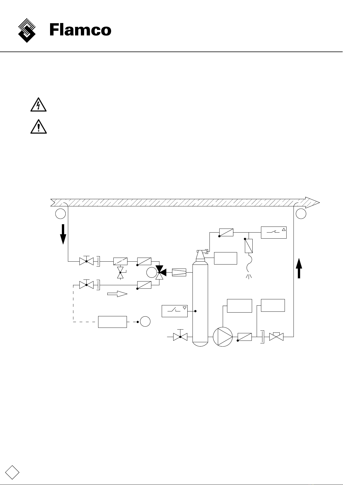
5.2 Plant layout
Systemdiagram:
Pvac
P
L
1
1
2
2
45
5
6 7 8
9
10
12
T
11 13
14
15
18
19
20 22
21
M
Psys
NFE x.x
A B
C2
3
16
A Supply to Vacumat Eco with gas-rich medium
B Return from Vacumat Eco to system circulation with degassed medium
C Top-up connection point (NFEx.2-variable,optionalwiring)
1 Ball valve
2 Flatsealingthreadedconnectiononnon-returnvalve
3 Fillinganddrainvalve
4 Dirttrap(0.5mm)
5 Check valve
6 3-wayswitchmotorballvalve
7 Volumeowlimiter
8 Degassing vessel
9 Temperature contact sensor
10 Filling level limit switch
11 Drainvalve(withcap)
12 Pumpwithfrequencyconverter
13 Check valve
14 Systempressuresensor
15 Cap valve
16 Special check valve
17 Sensor insulation
18 PressureSensor-degassingvessel
19 Automaticde-aerator
20 Aerationpreventer(checkvalve)
21 Vent line
22 Pressure switch
TemplateA4_v20130506
ENG
11
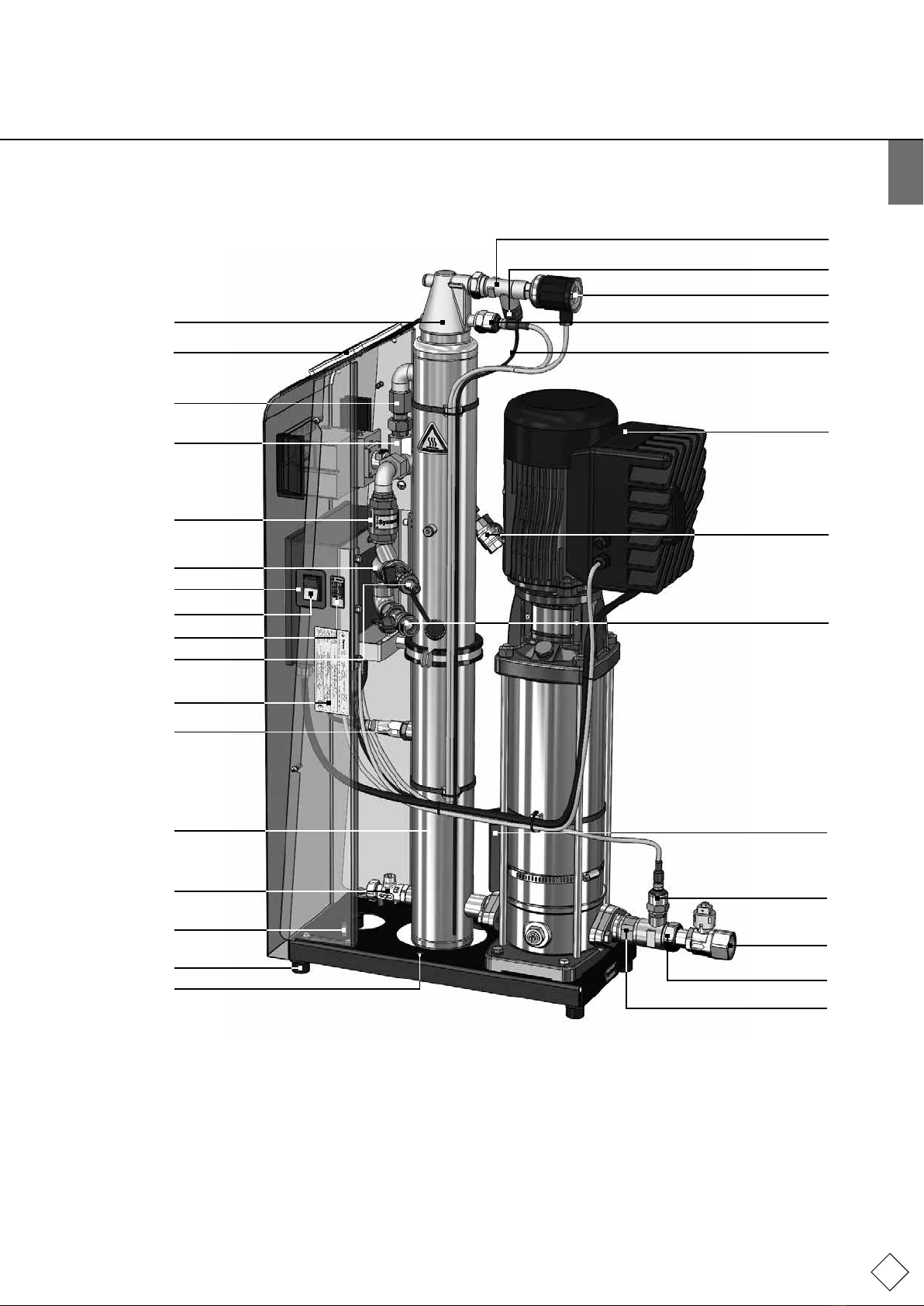
5.3 Components / equipment
22
18
21
12
1,C
1,A
9,17
14
B
2
13
16
20
19
27
7
6
5
4
28
23
24
3
25
10
8
11
26
30
29
23 Control unit ON/OFF switch
24 Servicelabelwithservicecontacts
25 Planttypeplate
26 Groundconnectionforapplyingtheexternalequipotentialbonding(protectiveearthconductor)
27 Operator terminal
28 Controlunit(SPCm1)
29 2xmountinghole(toensurestabilityagainsttipping)
30 Rubberbuffers(forsoundinsulation;insulationagainststructure-bornesoundpropagation)

TemplateA4_v20130506
12
5.4 Mode of operation
TheVacumatEcoworksasanactivedegassingdevicewithautomatictop-up
5.4.1 Basic principle of degassing in the Vacumat Eco
Degassingisperformedbyremovingsystemmediumfromthesystemcirculationthroughabypass.Thisisconveyedthroughthe
systemconnection(A)andthefollowingvolumeowlimiter(7)intothedegassingvessel(8).Duringpumpoperation,thedegassing
vessel(8)isplacedunderadenednegativepressure.Theabilityofairtodissolveinthesystemmediumisheavilyreducedbythe
loweredpressure,causingbubblestoform,accumulateandexpandandthisairtorise.
Theprocessisfacilitatedbytherotatingairseparatorprinciplewheretheairisseparatedanduniedbythetangentialinow,
intensiedtowardsthemiddleofthevessel(intheairheadofthedegassingvessel).Thisoptimisesdegassing.
Allfreegasesandaproportionofdissolvedgasesareremovedfromthesysteminanenergy-savingmannerwhichisconsidered
non-criticalintermsof:
• Corrosion.
• Heattransfertoheatingsurfaces.
• Flowbehaviourinthesystem.
Thisworks,amongotherreasons,becausethefrequency-controlledpumpwithadjustedspeedgentlyregulatesthevacuumtobe
builtuptoanenergeticallymeaningfullevel(temperature-controlled),thusavoidingpressuresurges.
Afterreducingthepumpspeed,thevesselisplacedundersystempressurebysubsequentmediumow,resultinginthe
dischargeoftheaircollectedabovewaterlevelviathede-aeratorunit(16,19-22).
TheVacumatEcoperformscheckdegassingcyclicallyinordertoautomaticallypausethedegassingwhenthepresetgascontent
levelisreached.Thisischeckedanddecidedatthede-aeratorunit.
Pressureswitch(22)detectswhetherairstillexistsatchargelevel,whichleadstopresetvacuumcontrolatthedegassingsystemby
(Reduceddegassing=MIN,Normaldegassing[default]=MED,andStrongdegassing=MAX).
Thequantityofmediumsuppliedtothevesselisreturnedtothecirculationlinesystemconnection (B)returnviaabypasslinewhile
thepumpisrunning.Cyclicaldegassingtakesplacein“Fullyautomatic”mode.Inthismode,thepumprunningtime(vacuum
build-up)alternateswiththeejectionoftheseparatedair(reducedpumpspeed).
AlthoughtheVacumatEcoworksveryquietly,fullyautomaticdegassingoperationmodecanbeinterruptedbyfreelyprogrammable
breaks(e.g.,atnight).Itisalsopossibletoswitchoffdegassing.Thesystemistheninstandbymode.Topping-upcanstillbedonein
thismodeasneeded.
5.4.2 Top-up
Bothpressure-controlledandlevel-controlledtopping-upcanbeperformed.
Topping-upoccurswhenthemotorballvalve(6)switches;mediumthenpassesintotheEcoVacumatthroughthetop-upopening(C)
andisfedtothesystembythepump.
Topping-upinterruptsbreaksandstandbyoperatingmode,orfollowscompletedcyclesofnormaldegassingorcheckdegassing.
Ifthetop-uprequirementisactive,itisprimarytoallotherprocessesbecausethepressuremustbemaintainedaboveallelse.
5.4.3 Pressure-controlled top-up
Equivalenttofactorysettingtotop-uppressureholdingsystemswith(passive)diaphragmpressureexpansionvessels.
Thetop-upswitch-onandswitch-offpressurescanbeeditedinthepressurescreen.
5.4.4 Level-controlled or externally-controlled top-up (for active pressure maintenance)
Theoperatorhastheoptiontousethelevel-controlledtop-upforpressuremaintenanceusinganautomaticpressureholdingdevice.
(Seeterminaldiagram/electricalconnection)Topping-upoccurshereforaslongastheexternaltop-uprequestispresentand
VacumatEcovolumeortime-monitoringallowsit.
5.4.5 Top-up OFF
Top-upcanalsobedisabledviasoftwareintheStartmenu.

TemplateA4_v20130506
ENG
13
5.4.6 Operating mode - fully automatic
Oncethesystemhasbeenfullysetup(Startmenucompleted)andcommissioned,andthecontrolunithasbeenswitchedon,a
delayrstoccurs;thenthetemperatureinthemachineisinitiallyadjustedforapresetperiodbeforeitismeasured.Basedonthe
temperatureandthepresetcheckdegassingmode,theprocessinthevesselisregulatedsothat,afteracertaintime,itispossible
todetermineatthepressureswitchwhetherundissolvedairstillexistsinthemediumatthelevelpredenedbythedegassingmode.
Ifthisisnotthecase,noairisdischargedincheckdegassinganddegassingisinterrupted;then,afterreadjustingthetemperature,
thegasloadistestedagainandtheprocessisrepeated.
However,ifairisdischargedfromthevesselinthecheckdegassingdischargephase,checkdegassingisfollowedbynormal
degassing;alowernegativepressureisbuiltupthanincheckdegassingandthemediumisundersaturatedwithrespecttothe
existinggascharges.Thisisrepeatedcyclicallyuntileithercheckdegassingispending,orthesystemswitchestoadegassing
waitbecausenoairisdischargedattheendofthedischargephaseduringnormaldegassing.Thesystemthencontinueswiththe
temperatureadjustmentsandcheckdegassingafteraspeciedintervaltime.
t
n
Zyklenablauf Vacumat ECO 20150417
5.4.7 Standby operating mode
Topping-uponlyoccursinthismodeduring"virtuallypermanentpauses"innormaldegassing,andthusinterruptsthepauses.
Checkdegassingisnotperformed.
Inaddition,thestandbysettingcanalsobeinducedbybridgingcontact39and40(takespriorityoverthesoftwaresetting).
Thiscanbeusedto,forexample,switchoffdegassingremotelyoralsotointerruptdegassingwhenthecirculationpumpsare
switchedofftopreventinefcientdegassing.ItisnotnecessarytowaituntiltheVacumatEcodetectsthisproblem(withadelay)
aftercheckdegassingorbecausenogasisdischargedduringnormaldegassing.
5.4.8 Break times / exclusion times with blocking intervals
Breaktimesfordegassingcanbedenedsothatatime-limitedstandbymodeisimplementedautomaticallyatcertaintimesofday.
Upto8blockingintervalscanbeimplementedperdayforthesebreakswhicharereferredtoasexclusiontimesinthisdocument.
5.4.9 Vacuum test
Requiresthesupplyconnectiontobeshutoffwhenthevesselisfull(comingfromthesystemreturn).Whendoingso,thepump
generatesavacuumafteracoupleofseconds;thevacuummustremainstableforaspeciedperiodoftimeinordertoverifythe
pump’sperformanceandensurethevesselisleak-tight.Thistestistypicallyneedstobeperformedpriortocommissioningand
aftermaintenance.
Generate vacuum Discharge
Decision:
Normal degassing or
interruption
Generate vacuum Discharge
Adjust
temperature
Switch-on
delay
Control unit ON
* Pump runs at a low speed level in order to achieve discharge pressure in the vessel.
** Pump runs at a higher speed level in order to build up the target vacuum in the vessel.
*** Pump runs at a high speed in order to build up a stronger vacuum in the vessel and degas effectively.
Pump OFF
Pump ON*
Pump ON**
Pump ON***
Pause
normal degassing
Cycle
Normal degassing
Cycle
Check degassing
TemplateA4_v20130506
14
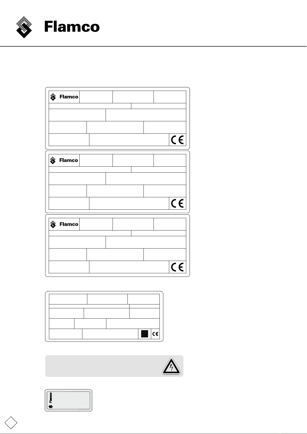
5.5 Marking
(withexamplesandplaceholdersforvariableinformation)
5.5.1 Type plates
Flamco STAG GmbH; Berliner Chaussee 29; 39307 Genthin; Germany
Typ:
Type:
Type:
Type:
Serien-Nr.:
Serial-No.:
N° de Série:
Volgnummer:
Nennspannung:
Nominal voltage:
Tension nominale:
Nominale spanning:
Vacumat Eco 900
1x 230 V 50/60 Hz
Zulässige Medientemperatur min. / max.:
Permissible media temperature min. / max.:
Température de média mini. / maxi. admissible:
Toegestane temperatuur media:
3 / 90 °C
Nennstrom:
Nominal current:
Courant nominal:
Nominale stroom:
6,8 A
Zulässiger Betriebsüberdruck:
Permissible working overpressure:
Surpression de service admissible:
Toelaatbare werkdruk:
-1/+10 bar
Herstellungsjahr:
Year of manufacture:
Année de fabrication:
Jaar van vervaardiging:
20xx
Nennleistung:
Nominal power:
Puissance assignée:
Nominaal vermogen:
1,1 kW
Zulässige Umgebungstemperatur min. / max.:
Permissible ambient temperature min. / max.:
Température de ambiante mini. / maxi. admissible:
Toelaatbare omgevingstemperatuur min. / max.:
3 / 45 °C
Schutzart:
Protection:
Protection:
Bescherming:
IP 42
Flamco STAG GmbH; Berliner Chaussee 29; 39307 Genthin; Germany
Typ:
Type:
Type:
Type:
Serien-Nr.:
Serial-No.:
N° de Série:
Volgnummer:
Nennspannung:
Nominal voltage:
Tension nominale:
Nominale spanning:
Vacumat Eco 600
1x 230 V 50/60 Hz
Zulässige Medientemperatur min. / max.:
Permissible media temperature min. / max.:
Température de média mini. / maxi. admissible:
Toegestane temperatuur media:
3 / 90 °C
Nennstrom:
Nominal current:
Courant nominal:
Nominale stroom:
5,18 A
Zulässiger Betriebsüberdruck:
Permissible working overpressure:
Surpression de service admissible:
Toelaatbare werkdruk:
-1/+10 bar
Herstellungsjahr:
Year of manufacture:
Année de fabrication:
Jaar van vervaardiging:
20xx
Nennleistung:
Nominal power:
Puissance assignée:
Nominaal vermogen:
1,1 kW
Zulässige Umgebungstemperatur min. / max.:
Permissible ambient temperature min. / max.:
Température de ambiante mini. / maxi. admissible:
Toelaatbare omgevingstemperatuur min. / max.:
3 / 45 °C
Schutzart:
Protection:
Protection:
Bescherming:
IP 42
Flamco STAG GmbH; Berliner Chaussee 29; 39307 Genthin; Germany
Typ:
Type:
Type:
Type:
Serien-Nr.:
Serial-No.:
N° de Série:
Volgnummer:
Nennspannung:
Nominal voltage:
Tension nominale:
Nominale spanning:
Vacumat Eco 300
1x 230 V 50/60 Hz
Zulässige Medientemperatur min. / max.:
Permissible media temperature min. / max.:
Température de média mini. / maxi. admissible:
Toegestane temperatuur media:
3 / 90 °C
Nennstrom:
Nominal current:
Courant nominal:
Nominale stroom:
2,85 A
Zulässiger Betriebsüberdruck:
Permissible working overpressure:
Surpression de service admissible:
Toelaatbare werkdruk:
-1/+10 bar
Herstellungsjahr:
Year of manufacture:
Année de fabrication:
Jaar van vervaardiging:
20xx
Nennleistung:
Nominal power:
Puissance assignée:
Nominaal vermogen:
0,4 kW
Zulässige Umgebungstemperatur min. / max.:
Permissible ambient temperature min. / max.:
Température de ambiante mini. / maxi. admissible:
Toelaatbare omgevingstemperatuur min. / max.:
3 / 45 °C
Schutzart:
Protection:
Protection:
Bescherming:
IP 42
5.5.2 SPC m1 control unit type plate
Herstellungsjahr
Année de fabrication
:
:
:
Year of manufacture
20XX
Tension assignée d'emploi
Bemessungsbetriebsspannung
Rated operational voltage
:
:
:
Phasenzahl
Nombre de phase
Number of phases
1
:
:
:
Frequenz
Fréquence
Frequency
:
:
:
Volllaststrom
Courant de coupure
:
:
:
Bemessungskurzschluss-Strom
Mesure de la courant de court-circuit
:
:
:
Dokumentationsnummer
Numeró de dessin :
:
:
Schutzart
Protection
Degree of protection IP54
:
:
:
Flamco STAG GmbH; Berliner Chaussee 29;
39307 Genthin; Germany
Cut-off current 16A
Rated short-circuit current 16A
Drawing number 952-19.13.27-1
Typ :
Type:
:Type Serial-No.
Serien-Nr.
N° de série
:
:
:
Classe de protection
Protection class
I
Schutzklasse
:
:
:
SPC m1/1.2 - lw
50/60Hz
±1%
230V
±10%
5.5.3 Electrical safety
high voltage! Opening by qualified personnel only.
gefährliche Spannung! Nur vom Fachpersonal zu öffnen.
Disconnect the unit from the power supply before opening it.
Vor dem Öffnen des Gerätes spannungsfrei schalten.
Attention,
Achtung,
5.5.4 Service numbers
Service Germany
+49 0 2052 887 969
+49 0 2052 887 69
Fax.:
Tel.:
Service Nederland
+31 0 33 299 7500
+31 0 33 298 6445
Tel.:
Fax.:
()
)(
)
)(
(
TemplateA4_v20130506
ENG
15
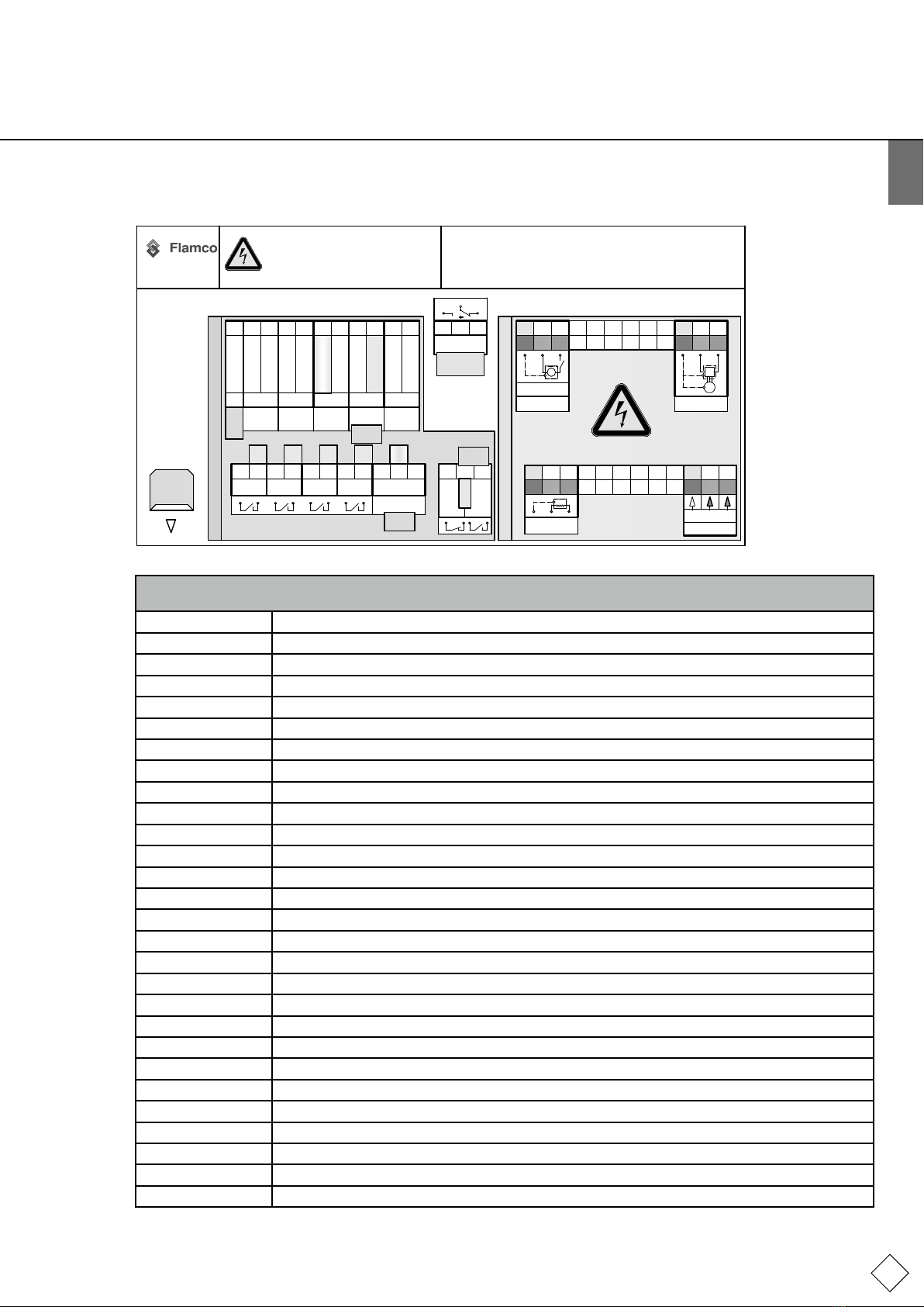
5.5.5 Label from the terminal board cover (inside)
31 32 33 34 35 36 37
1 3 6 7 8 9 10 11
+24V
counter
signal -
analog IN
sensor
SPC m1/V1.0
45 46 48 49 51 52
N
16 17 22 23 25 26
N L
~
N L
signal in
mains supply
230V 50/60Hz
44 47 50
PE
15 21 24
PEPE
extra - low voltage
Terminal
42 43
N L
41
PE
19 20
1812 13 14
38 39 40
fault
NCNO
2 4 5
27 28 29 30
+24V / signal +
Read the manual !
Bedienanweisung lesen !
+24V / signal +
signal -
GND
INPUT
FC OUT
OUT +
OUT -
4 - 20 mA
refill IN 230V FU/ FC
level
switch
pressure
switch refill release
FC
5A
5A 30
250 VDC
VAC
ohmic load
Störung FU
Standby
GND
sensorsensor
ATTENTION:
Even if unit is isolated from
power supply, terminals 12,
13, 14, 16 and 17 may carry
230V voltage!
ACHTUNG:
Trotz Netztrennung kann, an
den Klemmen: 12, 13, 14, 16
und 17 eine Spannung von
230V anliegen !
FC
M
fault FC
system
temperature
pwm
pressure
vessel
pressure
analog
out
0 - 10 V
OUT
analog
out
motor ball valve
high voltage (230V 50/60Hz)
option
L
RS232
option
11.06.2015
option
option
GND
GND
GND
GND
GNDA
AGND
Klemmenplan Vacumat ECO 20150708
Explanation of the abbreviations on the label on the terminal board cover.
Note:Theswitchsettingsshownrepresentthecurrent-free,non-switchedstate.
FU/FC Frequencyconverter
rellIN230V Top-up signal input 230V
extra-low voltage Protective low voltage
fault Fault,commonfaultoutput
MMotor(pumpmotor)
high voltage Voltage as per markings
L Phase
N Neutral wire
PE Protectiveearth(PE)conductor
mainssupply Powerfeed
NO normallyopen(volt-freeinopenposition)
NC normallyclosed(volt-freeinclosedposition)
pwm Inputforwatermeterwithpulseoutput(option)
sensor Sensor
systempressure Systempressuresensorinput
vessel pressure Vessel pressure sensor input
temperature Temperature sensor input
FC out FC out
ohmicload Ohmicload,resistance
motorballvalve Motorballvalve
level switch Levelswitch/oatswitch/dryrunprotection
pressure switch Pressureswitchcontrolleddegassing
rell Top-up
release FC release FC
standby standby
mainssupply Mainsfeed
GND/AGND/GNDA Mass(A=analogue,onlyconnectedasperterminaldiagram)
out analogue out analogue
TemplateA4_v20130506
16
6. Assembly
6.1 Installing, levelling, bolting - Ensure stability!
Setuptheunitonaatandstable(concrete)surfacenearthewellintheoperating/boilerroom.
Ensure that a oor drain is available for the unit.
Usebothframeholesonthebaseplate(Ø12)tosecuretheVacumatEcoagainsttipping.Usesufcientlylong(stainless)
steelscrewsØ10(withplugsandpossiblyplasticwashers)forthisinordertoanchortheminthegroundinsuchawaythattipping
canbeprevented,butsothatthescrewdoesnottransmitstructure-bornenoise.(Donottightenthescrewtootightly.)
Notetherequiredminimumdistancestowalls,maintenanceareasandassemblyareas(seeAppendix1)
6.2 Connecting the pipework
Note:Onlyworkingtemperaturesofbetween3and90°Carepermissible.Bearthisinmindwhenselectingtheplaceofinstallation.
Makesurethatthisconnectionismadesolelywiththeheatgeneratorandthattherearenoexternalhydraulicpressureinuences
presentatthepointofentrainment(e.g.hydraulicbalancers,distributors).
PipelinediametersmustbeatleastsizeDN32ontheunit'spressureports.
Ifthepipeworklengthismorethan10metresfromthepressureportstothereturnpipe,theconnectionpipesmustbeatleast
DN40.TheinletconnectionsfromthesystemandtoppingupmustbeatleastDN20.AtleastDN25mustbeusedforpipelines
longerthan10m.Thebranchpipeconnectionlengthstothesystemmustnotexceed20m.
Usesealantsandfeedlinesappropriatetotheinstallation;however,pleaseobserveatleastthemaximumpermittedvolumetricow,
pressureandtemperaturevaluesforthepipeworkinquestion.
Make sure that all connections to the unit are installed so that they are without tension at the joints!
Reinforced hoses must not be subjected to tension, twisting or kinking, etc. If a reinforced hose is used on the inlet to the
unit it must be designed to be vacuum-tight!
6.3 Connecting the electrical supply
ThepowersupplyconnectionmustbecreatedbythecustomerbetweenthemainssupplyandtheSPCm1.
Themainssupply,earthingsystemandcableprotectionmustbeprovidedincompliancewiththerequirementsoftheresponsible
powersupplycompany(PSC)andtheapplicablestandards.Therequiredinformationcanbefoundonthetypeplateofthecontrol
unitandtheterminalplan(labelling;Appendix4).
ThemainsconnectiontobeprovidedviaasuitableCEEplug/socketcombinationwithload-switchingabilityorotherpermissible
mainswitch.
Thiselectricalinstallationworkmustbeperformedbyaqualiedelectricallyskilledpersonnel.
Note:installequipotentialbondingbetweentheearthconnectionandequipotentialbondingconductor.Theminimumdiameter,
qualityandtypeofthepowercablesmustcomplywiththerulesandregulationsapplicableattheinstallationlocationforthis
application.Electricalpowercablesshouldbeguidedalongcableguttersatalltimes.
Thenishedsystemallowstheusertoprogramthecongurationandsystem-dependentparametersintothecontrolunit.
For more detailed instructions regarding the top up function check additional instructions at www.amcogroup.com.
7. Commissioning
7.1 Commissioning
Keepacommissioninglog!
Checkthattheinstallationandassemblyactionsarecomplete(e.g.powersupplyavailableatthemainsdistributionboard,
functioningoractivatedfusesandprotectiveconductorconnections,equipmentisfreefromleaksandthestablesetupoftheunit).
1. Afterthecapvalveandtheballvalveontheunithavebeenopened,thepumpautomaticallyde-aerated,thevessellledwith
systemmedium,theaircompletelydischargedfromthevesselviathede-aeratorunitandthesystemimpermeabilityischecked,
thecontrolunitcanbeswitchedon.Firstthecontrolunithardwarestatusandthenthesoftwarestatusaredisplayed.
2. NowstartworkingthroughtheStartmenu.Youmayneedtobeloggedonwiththeappropriateaccesscodeforanydelegated
responsibilities.Iftheresponsibilitiesaredelegatedtothecustomer/operatororpresetexworks(asinmostcases),youwillnot
needaspecialaccesscodetoworkthroughtheStartmenu.
3. AfterconrmingthelastmenuitemintheStartmenu:"START",thesystemstartsfullyautomaticoperation.
TemplateA4_v20130506
ENG
17
7.2 Settings / control actions
IndividualcontrolactionscanbeperformedbytappingthesensorsurfacesmarkedwithLEDsorwithngermovementsonthe
sensorwheel.WhenyouhaveworkedthroughtheSTARTmenuandthesystemhasstartedup,thesystem'sstatuscanbeprecisely
monitoredusingvariousoperationalindicators(1to3)includingstatisticalanalysisofthesystemvalues.Thebasicmenustructure
canbefoundinAppendix3ofthisdocument.
ItispossibletochangetheexistingsettingsviatheCONFIGURATIONafter"START".Asthechangetothetop-upcontroltypeis
abasiccongurationandpossiblyalsodenedbytheequipmentlevel,thisisonlypossibleviatheSTARTmenu.Tothisend,the
systemisstoppedwhenthe"ResetStartmenu"itemisselectedinCONFIGURATION,andanewversionoftheSTARTmenuis
workedthroughbasedonappropriateprompts.(Forthispurposeitmaybenecessarytorepeatthepressuresettingsastheymay
havebeenresettothefactorysettings.)
7.3 Recommissioning
Recommissioning(e.g.,afterextendedperiodsofinactivity/shutdownandmaintenance)assumesthatthesystemisfreefromleaks
andcorrectlyconnectedelectrically.Afterextendeddowntimesitisadvisabletoperformmaintenancebeforerecommissioning.
7.3.1 Visual check of the temperature contact sensor - check assembly
FortheVacumatEcotofunctioncorrectly,itisessentialthatthetemperaturesensor(Pos.9inthesystemdiagram)hasareliable,
xedcontactwiththepumpbodythroughthetensioningstrapthatattachesittothepumpbody.Itisalsoveryimportantthat
thetemperaturecontactsensorissufcientlyshieldedagainstambienttemperatureswiththesensorinsulation(pos17).
Thismustalwaysbecheckedduringcommissioning,systeminspection,servicingormaintenance!
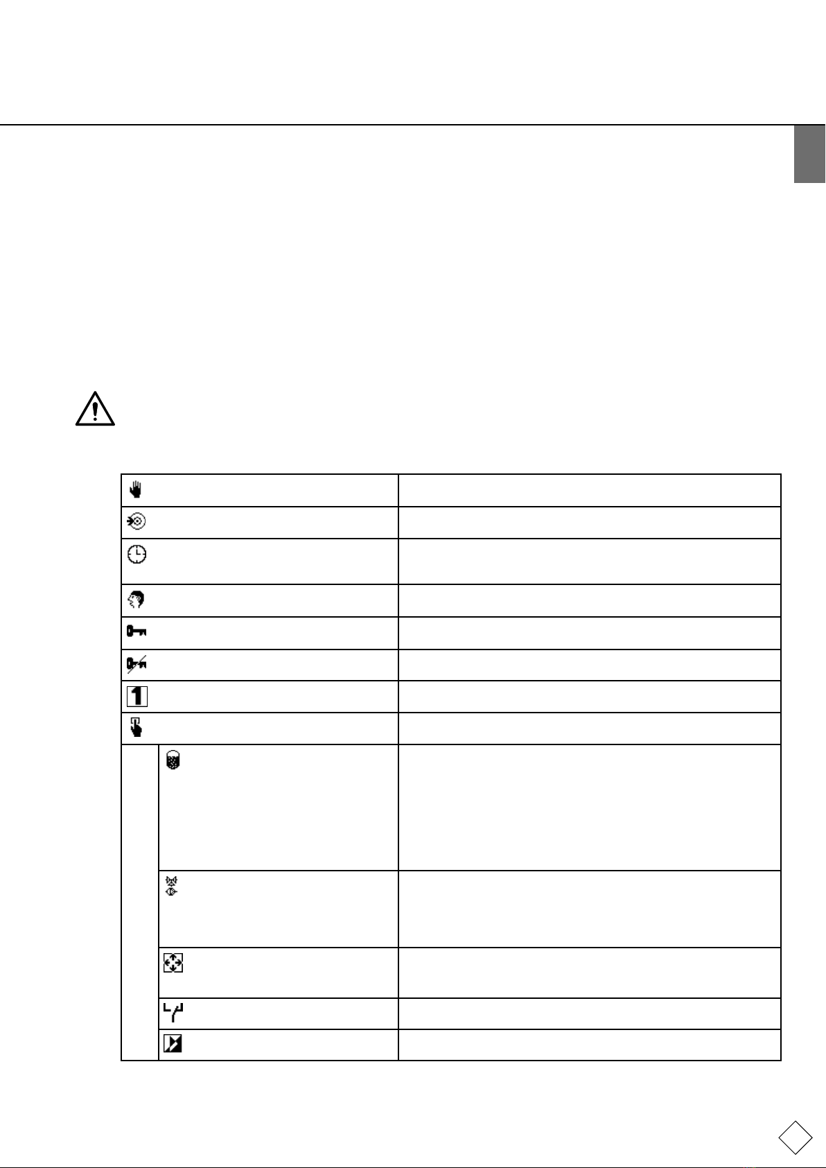
7.4 Explanations relating to the SPC m1 control menu
Explanations relating to the SPC m1
control menu Testing data points
alsoincludesavacuumtest.
Menu item 2: Data transfer makesitpossibletoperformsoftwareupdatesfortheSDcardviathe
extensionmoduleortoreaddata.
Menu item 3: Date / time mustbeusedtosetthecorrecttimeonthecontrolunit.(Thesystem
clockisbatterybufferedandlastsforabout10yearswithoutamains
connection.)
Menu item 4: Language canbeselectedtochoosealanguageforcommunicatingwiththecontrol
unitfromuptotwentydifferentlanguages.
Menu item 5: Log in supportstheentryofaccesscodesinorderforservicestafftocarryout
settings,includingsettinginternalFlamcoparameters.
Menu item 6: Logout supportsloggingoutafterusingaccesscodes.
Menu item 7: Inaccessibleforthecustomer/operator.
Menu item 8: Conguration allowsuserstosetorchangethedifferentdefaultsthatarerelevantfor
operatingthesystem.
Degassing modes 8-1:
Default → Fully automatic
Optional → Standby
Blocking times
Check degassing
(settingup)(softwaredefault)Onlytop-upispossiblehere!
fordegassing.Nighttimebreakscanbesetup,forexample.
Checkdegassingtype.Checkforgasresidualsolutioncontent:
8ml/lofair=MAX
12ml/lofair=MED
15ml/lofair=MIN
Top-up 8-2:
Top-up capacity 8-2-1-3:
Parameter list 8-2-2:
Preconfiguration50L(whenpulsewatermeterandmakeupare
configuraredbytheSalesEngineerorserviceDepartment).
Accept/edittop-updefaults.
Pressure 8-3:
Pressure settings 8-3-1: Default →Editfactorysettings.*
Error messages 8-5: Default →16grouperrormessagesnotoncontact.
Reset Start menu 8-6: →Activateeditingmode!
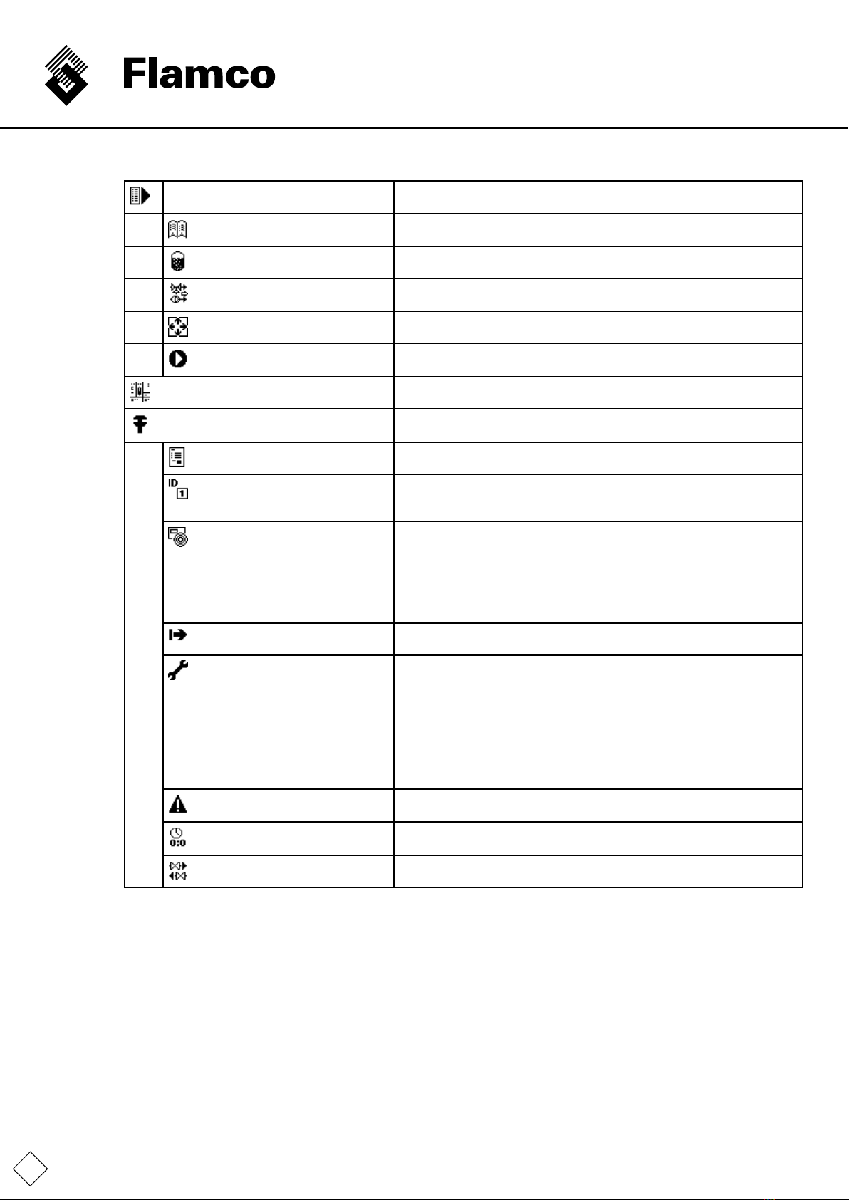
TemplateA4_v20130506
18
Menu item 9: Start-up menu Onlyavailableaslongasithasnotyetbeenfullyprocessed,forexample,
afterinitialcommissioningorresettingtheStartmenuinthe"Conguration".
Read the instruction manual 9-1:. →Readandacknowledge.
Degassing modes 9-4: →Choosebetweenfullyautomaticandstandby.
Control type 9-5: →pressure-controlled,externally-controlledortop-upOFF
seealsoTop-upsection.
Pressure settings 9-6: →Editpressuresinthediagram.
START 9-7: →TriggersystemSTART;jumptooperatingdisplay1.
(Thecommissioningtimeisalsologged.)
Menu item 10: Operating menu 3screens-seeAppendix3-Menustructureoverview.
Menu item 11: Service Menuitemforreadinginformationaboutthecontrolunitandtheoperation
alreadyperformedandfaults.
Order number 11-1 →Ordernumber/Date/Time/Inputcodelevel.
System info 11-2: →11-2-1SystemID/type
→11-2-2Degassingmode
→11-2-3Controltype
Version information 11-3: →11-3-1Controlunitsoftware/hardware
→11-3-2Terminalsoftware/hardware
→11-3-3Database
→11-3-4Bootloader
→11-3-5 Language file
→11-3-6VersionofanymodulesfittedinSLOT1
→11-3-7VersionofanymodulesfittedinSLOT2
Commissioning 11-4: Datecommissioning/time/codelevelduringcommissioning.
Maintenance 11-5:
11-5-1 Due date or comment
about the performed
maintenance 1
11-5-2 Due date or comment
about the performed
maintenance 2
11-5-3 Reset treatment
Recurringdevicetest(1year).
Recurringelectricaltest(1.5years).
Resetprocessingcapacitydate/time/codelevel.
History 11-6: →Faultcode/Fault/Date/Timeofoccurrence(upto100faultscanbe
traced).
Operating times 11-7: →Motorpump/motorballvalve/pressureswitch/degassingtotalsince
commissioning.
Top-up 11-8: →Top-upamount/top-uptime/top-uplist/processing.
* Flamco will not accept any liability for the consequences of incorrect parameterisation.
It may sometimes be necessary to rst edit a pressure value other than the intended one so that the actual value to be
changed receives enough space so that no implausibilities arise that could prevent system operation.
TemplateA4_v20130506
ENG
19
8. Maintenance
ThecomponentsoftheVacumatEcoarelargelymaintenance-free.
Nevertheless,itisrecommendedtoperformanannualvisualcheckofthesystem(includingforleaks).Inaddition,thedirttraptobe
providedbythecustomerintheinowlinemustbecleanedatleastonceayear,evenifautomaticdetectiondoesnotrequirethis.
Cleaningmayalsobedoneatmorefrequentintervals(dependingonhowdirtythesystemwateris).
Shouldavisualcheckofthesystemnecessitatefurthermaintenance,thismayalsoonlybedonebyqualiedpersonnel.
The temperature contact sensor must be visually inspected (Check assembly) at least during maintenance!
(alreadydescribedinCommissioning)
Itisalsorecommendedtoperformthevacuumtestaftermaintenance.
ThemenuitemServiceintheServicemenucanbeusedtoreadoffthenextservicedate.ThisshouldbeanaidfortheOperator.
Thenextservicedate(inbrackets)issavedhere.Ifthesystemclockiscorrectlyset,theOperatorwillbeinformedaboutreaching
thedateviaamessage.
365daysformaintenance1and548days(1.5years)formaintenance2areprovidedaftercommissioning.
TheVacumatEcocontinuestoworkwhenagrouperrormessageistriggered.
“Servicedone”shouldonlybeconrmedbyauthorisedstaff.Thecontrolunitthendeterminesthenextservicedateitself.
Maintenance 1standsformaintenancedevice.
Maintenance 2standsfortheperiodicinspectionofelectricalequipment.
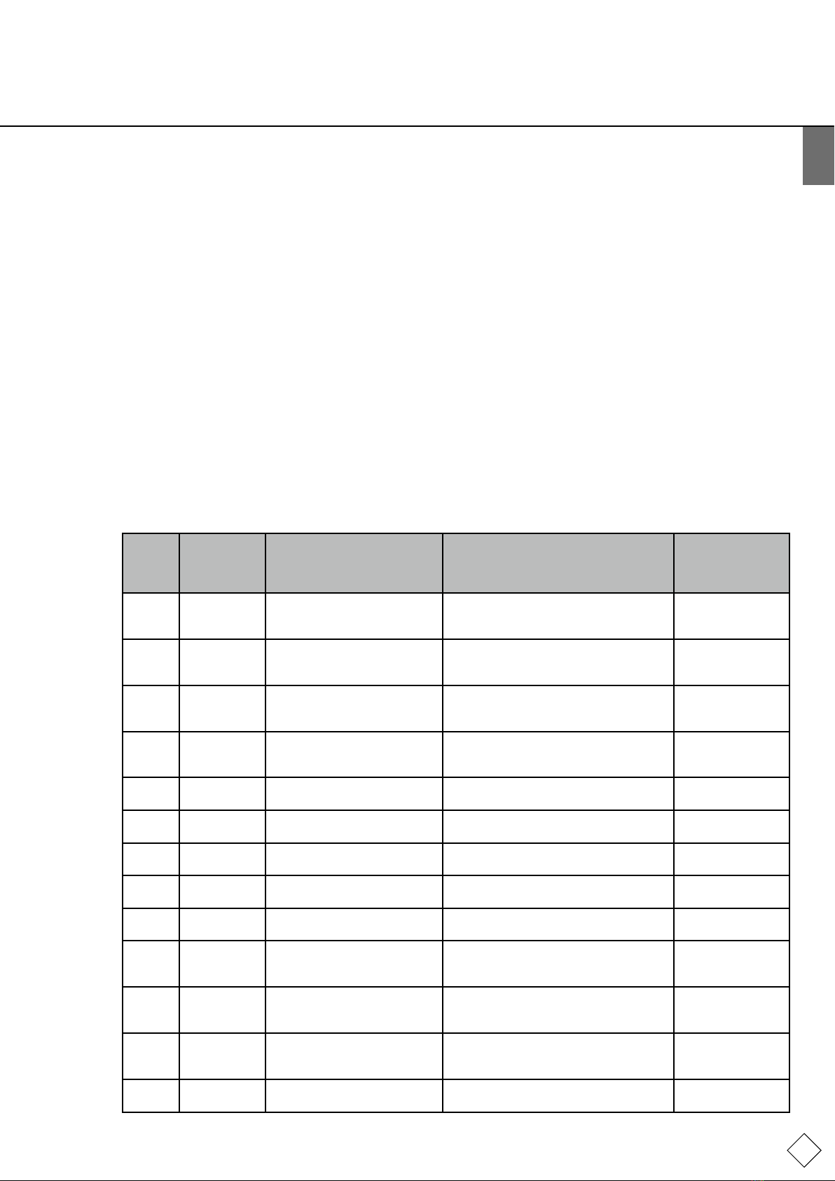
8.1 Malfunction list / error messages
Error
no. Error
message Error / Name Effect / Action holding /
subject to
mandatory
acknowledgement
2PS 20mA ↑Pressure sensor overcurrent /
sensor fault
Systeminforcedrest;motor,motorball
valveimmediatelyOff/Reducepressurein
system/changesensor.
NO
3PS 4mA ↓Pressuresensorcablebreak/
sensor fault
Systeminforcedidlemode;motor,motor
ballvalveimmediatelyOff/Repaircable/
changesensor.
NO
4VS 20mA ↑Vacuum sensor overcurrent /
sensor fault
Systeminforcedidlemode;motor,motor
ballvalveimmediatelyOff/Reduce
pressure/changesensor.
NO
5VS 4mA ↓Vacuumsensorcablebreak/
sensor fault
Systeminforcedidlemode;motor,motor
ballvalveimmediatelyOff/Repaircable/
changesensor.
NO
6↓↓ Temp Temperature sensor short circuit
/ sensor fault
Faultshutdown/Checkcableand
clamping/changesensor.
NO
7↑↑ Temp Temperaturesensorcablebreak
/ sensor fault
Faultshutdown/repaircable/change
sensor.
NO
8↓ Pressure Lower alarm limit pressure
undershot(Pamin)
Faultshutdown/Leadpressureinthe
workingpressurerange.
NO
9↑ Pressure Upperalarmlimitpressure
exceeded(Pamax)
Faultshutdown/Leadpressureinthe
workingpressurerange.
NO
12 ↓ Temp Temperaturerangeundershot Faultshutdown/guidetemperatureto
operatingtemperaturerange.
NO
13 ↑ Temp Temperaturerangeexceeded Faultshutdown/guidetemperatureto
operatingtemperaturerange.
Faultshutdown.
NO
14 TC / FC motor TC / FC message motor pump Systeminforcedidlemode;motor,motor
ballvalveimmediatelyOff/switchoff,5
minbreak,switchon.
YES
15 Dryrunning Filling level limit in the vessel
permanentlyundershot
Systeminforcedidlemode;motor,motor
ballvalveimmediatelyOff/expandsupply
line,excludepressureportcontraction.
YES
22 Top-up
volume ↓
IWZ(pulsewatermeter)delivers
nowateraftertop-uprequest
Top-upoff/Ensuresupply. YES
TemplateA4_v20130506
20
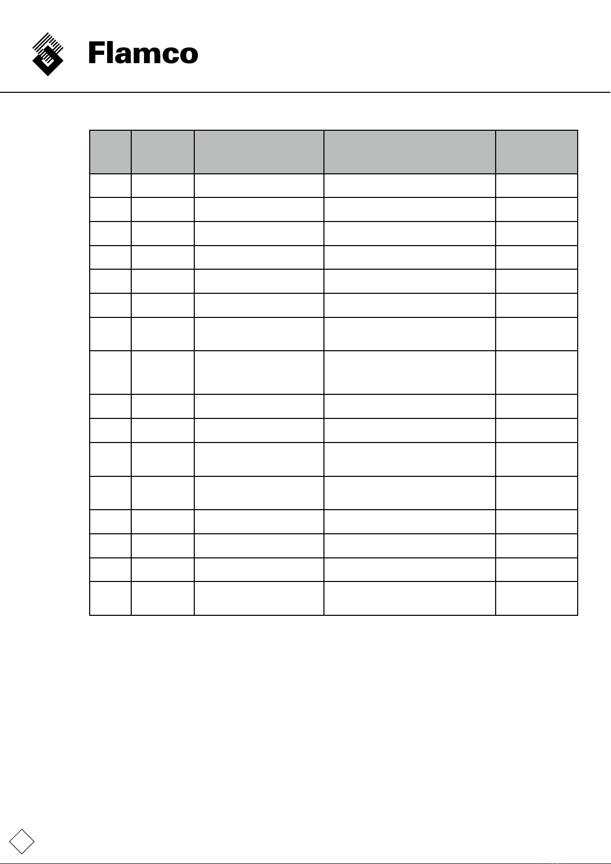
Error
no. Error
message Error / Name Effect / Action holding/
subject to
mandatory
acknowledgement
23 Top-up
inadmissible
Top-upwithoutrequest(IWZ
deliverssignalswithoutsupply)
Top-upoff/checkmotorballvalveforleaks
fortop-up.
YES
24 Top-up interval
↓
minimumtop-upcycleinterval
undershot
Top-upof/correctdefaultsifnecessary;
excludepipeburst.
YES
25 Top-up
number↑
maximumnumberofcycles
withinatimewindowexceeded
Top-upof/correctdefaultsifnecessary;
excludepipeburst.
YES
26 Top-up
volume ↑
Maximumvolumeexceededina
top-upcycle(withIWZ)
Top-upof/correctdefaultsifnecessary;
excludepipeburst.
YES
27 Top-up time ↑Maximumtimefortop-upcycle
exceeded(withoutIWZ)
Top-upof/correctdefaultsifnecessary;
excludepipeburst.
YES
31 v 3 ↑Watertreatmentmodule
processingamountexceeded
Top-upoff/correctdefaultsifnecessary;
replacetreatmentmodule.
YES
35 Temp
controller
Pressurecontrollerfaulty Faultshutdown-targetpressureinvessel
notreached/contactservice.
Possibilityofacontaminatedlter.
YES
37 P output Dischargepressurenotreached
withinthe"maximumduration
for waiting for ejection pressure
cycleendtobereached"
Faultshutdown-targetpressureinvessel
notreached/contactservice.
Possibilityofacontaminatedlter.
YES
39 Pa max ↑Pamaxexceeded Faultshutdown/Reducepressuretowithin
theworkingpressurerange.
YES
41 Adjustpsys Adjustsystempressurefault Motorshutdown/Ensureinletpressurefrom
thesystem.
YES
42 No
characteristic
curve
Novaliddegassingcharacteristic
curve
Novaliddegassingcharacteristiccurve. YES
55 v 1 ↑Watertreatmentmodule
processing amount warning
threshold1
No/Preparemodulereplacement.
(consumptionat70%)
YES
56 Maintenance
1!
Nextmaintenancetype1is
pending
No/Performmaintenance1. YES
57 Maintenance
2!
Nextmaintenancetype2is
pending
No/Performmaintenance2. YES
60 Extension Lastexternalmoduleactionwith
errorsended
No/repeatactionifnecessary. YES
61 v 2 ↑Watertreatmentmodule
processing amount warning
threshold2
No/preparemodulereplacement
(consumptionat90%)performmodule
replacementimmediatelyifnecessary.
YES
If any errors other than those described occur and they cause permanent problems (not self-acknowledging), please contact
the service to solve the problem!
This manual suits for next models
3
Table of contents
Languages:
Other flamco Water Filtration System manuals

flamco
flamco FlexBalance EcoPlus C Series User manual

flamco
flamco Flamcovent Smart Owner's manual

flamco
flamco Clean Smart User guide

flamco
flamco Flamcovent Clean Smart User manual

flamco
flamco Flamcovent Clean Smart User guide

flamco
flamco Flamcovent Smart User guide

flamco
flamco Flamcovent Clean F User manual

flamco
flamco MeiFlow Shunt UD DN15 S Installation and maintenance instructions

flamco
flamco Clean User manual

flamco
flamco Clean User manual


