manuals.online logo
Brands
  1. Home
  2. •
  3. Brands
  4. •
  5. Fleischmann
  6. •
  7. Toy
  8. •
  9. Fleischmann 665201 User manual

Fleischmann 665201 User manual

665201 Drehscheibe für Mittelleiter-Gleissysteme
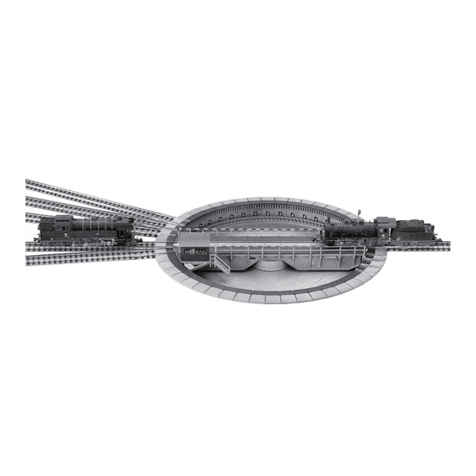
Fig.1: Die FLEISCHMANN-Drehscheibe 665201 wurde als Einbau-Drehscheibe konstruiert und ist für das Mittelleiter-Wechselstromsystem verwendbar.
Mit Grube und Drehbühne ist das große Vorbild modellgetreu nachgebildet. Die Drehscheibe ist elektrisch angetrieben und über den beiliegenden Dreh-
scheibenschalter 6910 fernsteuerbar. Der Schalter passt zum FLEISCHMANN-Gleisbildstellwerk.
Fig. 2: Zum Einbau der Drehscheibe wird in die Anlagenplatte ein Loch von 340 mm Ø gesägt, in das die Drehscheibe eingesetzt wird. Ein Festschrauben
ist nicht erforderlich, da die Drehscheibe über die zu befestigenden Zufahrtsgleise gehalten wird. Führen Gleise unterhalb der Drehscheibe vorbei, (z.B.
ein verdeckter Abstellbahnhof), so ist auf eine genügende Durchfahrhöhe zu achten, da die Drehscheibengrube eine Tiefe von 30 mm besitzt. Um ein
Entgleisen von Zügen oder Loks zu vermeiden, dürfen die Anschlusskabel nicht frei herabhängen, sondern müssen sauber verlegt werden.
BETRIEBSANLEITUNG
Operating Instructions • Instructions de service •
Gegebenenfalls kann die Drehscheibe auch auf
die Anlagenplatte aufgesetzt werden, der Dreh-
scheibenrand muss dann allerdings durch Füll-
stücke (z.B. Styropor) unterlegt werden. Ebenfalls
müssen in diesem Fall 30 mm hohe Auffahr-Ram-
pen für die Zu- und Abfahrgleise geschaffen wer-
den. Die Drehscheibe ist durch die 7,5°- Teilung
mit max. 48 Gleisanschlüssen bestückbar. Hierzu
ist der dreiständige Ringlokschuppen 6476 vor-
gesehen, der auch mehrteilig ausgebaut werden
kann. Der Lokschuppen 6476 ist vom Auffahrseg-
ment der Drehscheibe im Abstand von 204 mm
aufzustellen. Pro Lokstand werden ca. 325 mm
Gleis benötigt. Diese werden durch die vorderen
Tore eingeschoben und von den Halteklammern
der Grundplatte gehalten. Die einzelnen Gleise
werden in Richtung Drehscheibe etwas herausge-
zogen und mit je einem Auffahrsegment zusam-
mengesteckt. Die Drehscheibe kann aber auch für
15°-Teilung Verwendung nden. In diesem Fall
ist zwischen den einzelnen Abstellgleisen jeweils
eine Abdeckplatte zu belassen.
Einbau
665201
6910
80665201920 FLM X_2023.indd 180665201920 FLM X_2023.indd 1 19.10.2023 08:27:4719.10.2023 08:27:47
Ansteuerung der Gleisabgänge (Fig. 4)
Mit dem Drehscheibenschalter 6910 kann durch Betätigung des
schwarzen Tasters nach rechts oder links die Drehbühne in ent-
sprechender Richtung in Betrieb gesetzt werden. Die Drehbühne
hält automatisch an jedem der 48 möglichen Gleisabgänge an.
Ein kontinuierliches Durchlaufen zur gewünschten Position ist
möglich, wenn der Taster nach Drehrichtungswahl durch
Nachaußenziehen eingerastet wird. Kurz vor Erreichen der ge-
wünschten Position muss die Rastung durch Drücken in Gegen-
richtung wieder ausgelöst werden.
Motoranschluss der Bühne:
Die 3-fach-Litze mit den Farben Rot, Gelb, Grau
muss mit den entsprechenden Litzen des Schalters
6910 verbunden werden, z.B. über die Klemmen-
platte 6941. Die weiße Litze Aund die schware Lit-
ze Bdes Schalters muss an den Wechselstroman-
schluss ~ (bzw. O und L) des Trafos gelegt werden
(Anschlusswert 12 - 14 V / 0,5 A. Hand-Betätigung
der Drehbühne siehe Fig. 8 und Fig. 9.
Betrieb der Anlage mit zwei oder mehreren Regel-
Transformatoren
Der Drehscheibenbereich sollte mit einem gesonderten
Regel-Transformator betrieben werden. Grundsätzlich
sind alle Gleise am Übergang vom Drehscheibenbe-
reich in die Anlage durch Einbau von 2 Isolierschienen-
verbindern 6433 elektrisch zu trennen.
Achtung: Verbinden Sie erst alle Litzen des Schalters und der
Drehscheibe bevor Sie den Netzstecker des Trafos einstecken.
Sonst besteht die Gefahr der Zerstörung des Schalters auf-
grund von Kurzschlüssen!
Fig. 3
Fahrstromanschluss der Bühne:
Mittelleiter-Wechselstromsystem. Die gelbe Zwillingslitze C1+ C2der
Drehscheibe wird zusammen an die eine Klemme (O), die weiße Litze Dan
die andere Klemme (B) des Wechselstrom-Fahranschlusses am Regeltransfor-
mator angeschlossen.
Die Fahrstromzuführung zu den einzelnen Gleisen erfolgt über die Bühne
in Abhängigkeit von der Bühnenstellung. Es werden also nur die Gleise mit
Strom versorgt, in deren Richtung die Bühne steht. Alle anderen Gleise blei-
ben stromlos, so dass jederzeit Lokomotiven abgestellt werden können. Wäh-
rend des Drehens der Bühne muss der Fahrstrom ausgeschaltet bleiben.
AB
weiß
gelb
gelb
grau
gelb
rot
D
C
C
2
1
B
D
A + C + C
12
665201
Mittelleiter-
Wechselstrom-
System
LBO
Fig. 5
Fig. 6: Mit dem
Erweiterungsset
665301 kann die
Drehscheibe um je-
weils drei Gleisan-
schlüsse erweitert
werden.
Erweiterung
Fig. 7: Die Drehbühne ist hierzu aus dem Bereich der einzubauenden Teilstücke zu
fahren. Nunmehr sind die Abdeckplatten durch Zurückdrücken der federnden Zungen
nach oben herauszuziehen und die Auffahrgleise einzustecken. Jedem Auffahrgleis
ist gegenüber ein Blindstutzen oder wieder ein Auffahrgleis einzusetzen. Auffahr-
gleise und Blindstutzen beim Einbau eindrücken, bis sie fest einrasten.
Bei Verwendung der Drehscheibe
665201 für das Mittelleiter-Wech-
selstromsystem empfehlen wir die
Auffahrtsgleise aus der Grube zu
ziehen (Fig. 7) und diese Außerhalb
mit den Gleisen zusammenzufüh-
ren.
Fig. 4
80665201920 FLM X_2023.indd 280665201920 FLM X_2023.indd 2 19.10.2023 08:27:4819.10.2023 08:27:48
Handbetätigung der Drehbühne
Fig. 8: Gegenüber dem Maschinenhaus ist unterhalb der Drehbühne am Antrieb ein
Handhebel angebracht. Durch Drücken und gleichzeitiges Halten des Hebels in Rich-
tung Drehbühnenmitte rastet das Antriebsrad aus der Verzahnung der Grube aus
und die Drehbühne kann in beliebiger Richtung verstellt werden. Nach Loslassen
des Hebels greift das Zahnrad wieder ein. Darauf achten, dass die Gleisteilung der
Anschlussgleise mit dem Bühnengleis übereinstimmt.
Fig. 9: Sollte trotz Betätigung des Schalters 6910 der Antrieb klem-
men oder nicht anlaufen, so ist durch kurzes Drücken des Hebels in
Richtung Grubenrand der Antrieb in Betrieb zu setzen. Dieser hält
dann nach einer Gleisteilung wieder an.
Fig. 10: Um die Lager des Antriebsmotors ölen zu können, muss die Gitterabde-
ckung (2) vor dem Maschinenhaus mit einem kleinen Schraubendreher abgeho-
ben werden. Dazu müssen zunächst 2 gegenüberliegende Teilstücke am Gruben-
rand ausgebaut werden (Fig. 7). Jetzt wird die Brücke entsprechend Fig. 8 von
Hand auf die beiden Lücken gestellt und mit einem Schraubenzieher die Schrau-
ben (1) zwischen den Schienen der Bühne entfernt.
Ölen des Motors
Fig.11: Durch die vorgesehenen Lö-
cher ist je 1 Tropfen Öl an die durch
Pfeile gekennzeichneten Lagerstellen
zu geben. Vorsicht, nicht überölen! Nur
FLEISCHMANN-Öl 6599 verwenden.
Zur Dosierung die in der Verschlusskap-
pe der Ölasche angebrachte Nadel ver-
wenden.
Ausbau der Drehbühne
Läuft die Drehbühne auch nach Betätigung des Handhebels nicht
an, muss sie ausgebaut werden. Auf jeder Seite der Drehscheibe
werden mindestens 2 gegenüberliegende Teilstücke entfernt (siehe
Fig. 7). Mit einem Schraubenzieher die Schraube (siehe Fig. 10,1)
zwischen den Schienen der Bühne entfernen. Jetzt kann die Büh-
ne in diesen Ausschnitt gefahren und herausgehoben werden. Die
Kontaktbahnen neben dem Drehzapfen und die Kontaktfedern sind
zu reinigen. Der Einbau der Bühne erfolgt in umgekehrter Reihen-
folge.
TURNTABLE 665201
Fig.1: The FLEISCHMANN turntable 665201 was constructed as a built-in turntable for the H0 middle conductor AC system. Complete with trench and turning platform
this is a true-to-life model. The turntable is electrically operated and can be operated remotely by the turntable switch 6910, which is included. The switch will t into the
FLEISCHMANN diagrammatic control.
Installation (g. 2): For installing the turntable you will need a hole with 340 mm diameter in your layout board. It will not be necessary to fasten it down, as the turntable
will be stopped at fastened tracks. If the turntable has to be laid on top of the layout, a base of polystyrene (or similar) should be laid underneath. In this case entry and exit
ramps 30 mm high must be created for the tracks. The turntable is divided into 7.5° sections with a maximum of 48 possible rail connections. The 7.5° sections are provided
to match up to the standing positions of 3 locos in the loco shed 6476. The turntable can also be set up for 15° section operation. In this case only one cover plate should be
left between the sidings.
Connecting the motor of the platform (g. 3):
The 3 wires, red, yellow and grey must be connected to the corresponding wires on the switch, if necessary with the 6941connector. The black wire B and
white wire A from the switch 6910 must be connected to the AC winding of the transformator (marked ~, or O and L). Connecting value: 12 - 14 V / 0,5 A.
Rotating the turntable by hand, see g. 8 and g. 9.
Connecting current to the platform: Middle conductor AC systems. The two yellow twin-wire C1 + C2 of the turntable are connected to one (O), the white wire D to the other (B)
terminal of the AC drive current connection on the regulating transformer. Current for the rail itself depends on the position of the platform. thus only the line from the turntable
is provided with current. All the other lines remain without current, making it possible to leave locos there. Current must be turned off when the platform is being turned (g. 3).
Controlling the connecting track (g. 4):
With this turntable switch 6910 the platform can be turned either to the left or right by means of the black switch. The platform stops automatically at each track. A continuous
action through to your chosen position is possible if the switch is pushed into the direction of travel to its outer limit until the position is reached. On reaching this position, it
is stopped by pressing in the opposite direction.
Operation of the layout with two or more transformers (g. 5):
The turntable area should be controlled by a separate transformer/controller. All lines which go over into the turntable area should be cut off with two isolating sh plates 6433.
Extension (g. 6):
With the Extension Set 665301 the turntable can be extended by three rail connections. The turntable should be placed away from the area of the installed parts. The cover
plates are now pulled up by pushing back the spring switch-tongues (g. 7), and stuck in the approach track. Every approach track is to be set up opposite a blind section or
another approach track.
GB
80665201920 FLM X_2023.indd 380665201920 FLM X_2023.indd 3 19.10.2023 08:27:4819.10.2023 08:27:48
Änderungen von Konstruktion und Ausführung vorbehalten! • We reserve the
right to change the construction and design! • Nous nous réservons le droit
de modier la construction et le dessin!
Bitte diese Beschreibung zum späteren Gebrauch aufbewahren! • Please re-
tain these instructions for further reference! • Pi�re d‘bien vouloir conserver
ce mode d’emploi en vue d’une future utilisation!
Tel.: 00800 5762 6000 AT/D/CH (kostenlos / free of charge / gratuit)
International: +43 820 200 668
(zum Ortstarif aus dem Festnetz; Mobilfunk max. 0,42€ pro Minute inkl.
MwSt. / local tariff for landline, mobile phone max. 0,42€/min. incl. VAT /
prix d‘une communication locale depuis du téléphone fixe, téléphone mo-
bile maximum 0,42€ par minute TTC)
PLAQUE TOURNANTE 665201
Fig.1 : La plaque tournante FLEISCHMANN 665201 a été construite comme plaque tournante intégrée pour le syst�me de courant alternatif à conducteur central H0. Compl�te
avec une tranchée et une plate-forme de retournement, il s'agit d'un modèle dèle à la réalité. La plaque tournante est actionnée électriquement et peut être commandée à
distance par l'interrupteur de plaque tournante 6910, qui est inclus. L'interrupteur s'adapte à la commande diagrammatique FLEISCHMANN.
Installation (g. 2) :
Pour installer la plaque tournante, vous aurez besoin d‘un trou de 340 mm de diamètre dans votre plan d‘aménagement. Il n‘est pas nécessaire de le xer, car la plaque tour-
nante s‘arrêtera sur les rails xés. Si la plaque tournante doit être posée sur le plan, une base en polystyrène (ou similaire) doit être posée en dessous. Dans ce cas, des rampes
d‘entrée et de sortie de 30 mm de haut doivent être créées pour les voies. La plaque tournante est divisée en sections de 7,5° avec un maximum de 48 connexions de rails pos-
sibles. Les sections de 7,5° sont prévues pour correspondre aux positions debout de 3 locomotives dans le hangar à locomotives 6476. La plaque tournante peut également
être congurée pour fonctionner avec des sections de 15°. Dans ce cas, une seule plaque de recouvrement doit être laissée entre les voies de garage.
Raccordement du moteur de la plate-forme (g. 3) :
Les 3 ls, rouge, jaune et gris doivent être connectés aux ls correspondants de l‘interrupteur, si nécessaire avec le connecteur 6941. Le l noir B et le l blanc A de l‘interrupteur
6910 doivent être connectés à l‘enroulement CA du transformateur (marqué ~, ou O et L). Valeur de connexion : 12 - 14 V / 0,5 A.
Faire tourner la platine à la main, voir g. 8 et g. 9.
Raccordement du courant à la plate-forme : Systèmes à courant alternatif à conducteur intermédiaire. Les deux ls jumelés jaunes C1 + C2 de la plaque tournante sont
connectés à l‘une (O), le l blanc D à l‘autre (B) borne de la connexion de courant d‘entraînement CA sur le transformateur de régulation. Le courant pour le rail lui-même dépend
de la position de la plate-forme. Ainsi, seule la ligne de la plaque tournante est alimentée en courant. Toutes les autres lignes restent sans courant, ce qui permet d‘y laisser des
locomotives. Le courant doit être coupé lorsque la plate-forme est tournée (g. 3).
Commande de la voie de raccordement (g. 4) :
Avec cet aiguillage 6910, la plate-forme peut être tournée vers la gauche ou vers la droite à l‘aide de l‘interrupteur noir. La plate-forme s‘arrête automatiquement à chaque
voie. Une action continue jusqu‘à la position choisie est possible si l‘interrupteur est poussé dans le sens de la marche jusqu‘à sa limite extérieure, jusqu‘à ce que la position
soit atteinte. Une fois cette position atteinte, la plate-forme s‘arrête en appuyant dans la direction opposée.
Fonctionnement du réseau avec deux transformateurs ou plus (g. 5) :
La zone de la plaque tournante doit être contrôlée par un transformateur/contrôleur séparé. Toutes les lignes qui passent dans la zone de la plaque tournante doivent être
coupées à l‘aide de deux éclisses de séparation 6433.
Extension (g. 6) :
Le kit d‘extension 665301 permet de rallonger la plaque tournante de trois connexions de rail. Le plateau tournant doit être éloigné de la zone des pièces installées. Les plaques
de recouvrement sont maintenant tirées vers le haut en repoussant les languettes d‘aiguillage à ressort (g. 7), et coincées dans la voie d‘accès. Chaque voie d‘accès doit être
placée en face d‘une section aveugle ou d‘une autre voie d‘acc�s.
Rotation manuelle du plateau tournant (g. 8) :
En face du boîtier du moteur, sous la plaque tournante, se trouve un petit levier noir. En poussant le levier vers le centre, la roue dentée d‘entraînement est retirée des dents
de l‘anneau d‘entraînement extérieur, ce qui libère le plateau tournant et permet de la déplacer manuellement dans la direction souhaitée. Lorsque le levier est relâché, la
roue dentée est à nouveau engrenée dans la bague extérieure. Veillez toutefois à ce que les voies de rotation soient alignées sur les voies de sortie. Si la plaque tournante ne
fonctionne pas, il suft d‘appuyer légèrement sur le levier en actionnant l‘interrupteur 6910 pour que la roue dentée soit fermement enclenchée dans l‘anneau d‘entraînement,
ce qui la mettra en mouvement. Elle s‘arrêtera ensuite à nouveau sur la voie suivante (g. 9).
Huilage du moteur (g. 10) :
Pour lubrier les roulements du moteur, il faut enlever le couvercle de la grille située à l‘avant de la salle des machines. Pour ce faire, il faut d‘abord retirer deux parties opposées
de la fosse (g. 7). Le pont est ensuite placé à la main sur les deux interstices selon la gure 8 et la vis située entre les rails de la scène est enlevée à l‘aide d‘un tournevis (g.
10).Le couvercle de la grille est maintenant soulevé d‘un côté et repoussé en direction du bord de la fosse. Le couvercle de la grille se déverrouille alors et peut être enlevé.
Attention ! Ne pas égarer le ressort de contact situé sous la vis et le remettre correctement en place lors du remontage. Par les deux trous (g. 11) situés à l‘avant du comparti-
ment moteur, versez une goutte d‘huile sur les roulements marqués d‘une èche. Attention ! Ne pas appliquer trop d‘huile (uniquement de l‘huile FLEISCHMANN 6599).
Démontage de la plaque tournante
Si le plateau tournant ne démarre toujours pas après avoir actionné le levier manuel, il faut le démonter. De chaque côté du plateau tournant, on retire au moins 2 sections
opposées (voir Fig. 7). Avec un tournevis, enlever la vis (voir Fig. 10,1) entre les rails de la plateforme. La plate-forme peut maintenant être introduite dans cette découpe et être
retirée. Les pistes de contact à côté du pivot et les ressorts de contact doivent être nettoyés. Le montage de la plate-forme s‘effectue dans l‘ordre inverse.
F
Rotating the turntable by hand (g. 8):
Opposite the motor housing, under the turning table, is a small black lever. By pressing the lever towards the centre, the drive gear wheel is withdrawn from the teeth in the
outer drive ring releasing the table so that it can be moved manually in the desired direction. When the lever is released the gear wheel is again enmeshed with the outer-ring.
Ensure, however, that the rotating tracks are lined up with the exit tracks. Should the turntable not operate, when pressing the switch 6910, simply press the lever slightly to
ensure the gear wheel is rmly seated in the drive ring, which will then start it moving. It will then stop at the next track again (g. 9).
Oiling the motor (g. 10):
For lubricating the bearings of the motor, the grille cover in front of the engine room must be taken off. To do this, two opposite parts of the pit must rst be removed (g. 7).
Now the brigde is placed according to g. 8 by hand onto the two gaps and the screw situated between the rails of the stage removed by means of a screwdriver (g. 10).
The grille cover is now lifted up to one side and pushed back in direction of the pit border. By this, the grille cover unlocks and can be taken off . Attention! Do not misplace
the contact spring situated below the screw and ret correctly when reassembling. Through the two holes (g. 11) in front of the engine house one drop oil is to apply to the
bearings marked by arrows. Attention! Do not apply too much oil (only FLEISCHMANN oil 6599).
Dismantling the table
Should the turntable not operate by moving the lever, it will be necessary to dismantle the table. For this, proceed as already described for oiling. On each side of the platform
take off 2 opposing components (g. 7). Now the platform can be removed. The contact points and springs round the central pivot should be cleaned. To put the table back
together simply reverse the procedure. In the unfortunate instance that the turntable should still not function, please return it to your local dealer or to your supplier.
80665201920 X / 2023
Modelleisenbahn GmbH •5101 Bergheim •Austria
80665201920 FLM X_2023.indd 480665201920 FLM X_2023.indd 4 19.10.2023 08:27:4919.10.2023 08:27:49

Other Fleischmann Toy manuals

Fleischmann 340 Series User manual

Fleischmann

Fleischmann 340 Series User manual

Fleischmann Z21 Start User manual

Fleischmann

Fleischmann Z21 Start User manual

Fleischmann 9152 C User manual

Fleischmann

Fleischmann 9152 C User manual

Fleischmann N piccolo 7250 User manual

Fleischmann

Fleischmann N piccolo 7250 User manual

Fleischmann 7760006 User manual

Fleischmann

Fleischmann 7760006 User manual

Fleischmann 9475 User manual

Fleischmann

Fleischmann 9475 User manual

Fleischmann 6454 User manual

Fleischmann

Fleischmann 6454 User manual

Fleischmann 218 Series User manual

Fleischmann

Fleischmann 218 Series User manual

Fleischmann 413002 User manual

Fleischmann

Fleischmann 413002 User manual

Fleischmann 6950 User manual

Fleischmann

Fleischmann 6950 User manual

Fleischmann 644210 User manual

Fleischmann

Fleischmann 644210 User manual

Fleischmann 944001 User manual

Fleischmann

Fleischmann 944001 User manual

Fleischmann 642101 User manual

Fleischmann

Fleischmann 642101 User manual

Fleischmann 6452 User manual

Fleischmann

Fleischmann 6452 User manual

Fleischmann 717473 User manual

Fleischmann

Fleischmann 717473 User manual

Fleischmann BR 110 User manual

Fleischmann

Fleischmann BR 110 User manual

Fleischmann BR 215 User manual

Fleischmann

Fleischmann BR 215 User manual

Fleischmann 734076 User manual

Fleischmann

Fleischmann 734076 User manual

Fleischmann 9460 User manual

Fleischmann

Fleischmann 9460 User manual

Fleischmann 145 Series User manual

Fleischmann

Fleischmann 145 Series User manual

Fleischmann 87 7914 User manual

Fleischmann

Fleischmann 87 7914 User manual

Fleischmann Roco Z21 User manual

Fleischmann

Fleischmann Roco Z21 User manual

Fleischmann 931884 User manual

Fleischmann

Fleischmann 931884 User manual

Fleischmann Diesellok BR 203 User manual

Fleischmann

Fleischmann Diesellok BR 203 User manual

Popular Toy manuals by other brands

marklin 76371 manual

marklin

marklin 76371 manual

taf toys Penguin Play & Kick manual

taf toys

taf toys Penguin Play & Kick manual

Viessmann 6841 Operation manual

Viessmann

Viessmann 6841 Operation manual

Lionel 3376 owner's manual

Lionel

Lionel 3376 owner's manual

Mattel Barbie Says quick start guide

Mattel

Mattel Barbie Says quick start guide

Madcow Rocketry AGM 33 PIKE user guide

Madcow Rocketry

Madcow Rocketry AGM 33 PIKE user guide

Radica Games cupcakes 75052 instruction manual

Radica Games

Radica Games cupcakes 75052 instruction manual

Mattel Barbie T9080 instructions

Mattel

Mattel Barbie T9080 instructions

Schleicher ASH-26 manual

Schleicher

Schleicher ASH-26 manual

Silverlit YCOO NEO ROBO DACKEL instructions

Silverlit

Silverlit YCOO NEO ROBO DACKEL instructions

Reely Overheater X 4WD RtR operating instructions

Reely

Reely Overheater X 4WD RtR operating instructions

Kyosho Caliber 30 instruction manual

Kyosho

Kyosho Caliber 30 instruction manual

Maxford USA Albatros D.III instruction manual

Maxford USA

Maxford USA Albatros D.III instruction manual

Eduard He 111Z exterior quick start guide

Eduard

Eduard He 111Z exterior quick start guide

Trix Minitrix BR 218 217 manual

Trix

Trix Minitrix BR 218 217 manual

Eduard He 162A Spatz interior quick start guide

Eduard

Eduard He 162A Spatz interior quick start guide

roundhouse FOWLER Owner's handbook

roundhouse

roundhouse FOWLER Owner's handbook

RC Factory VELOXITY manual

RC Factory

RC Factory VELOXITY manual

manuals.online logo
manuals.online logoBrands
  • About & Mission
  • Contact us
  • Privacy Policy
  • Terms and Conditions

Copyright 2025 Manuals.Online. All Rights Reserved.