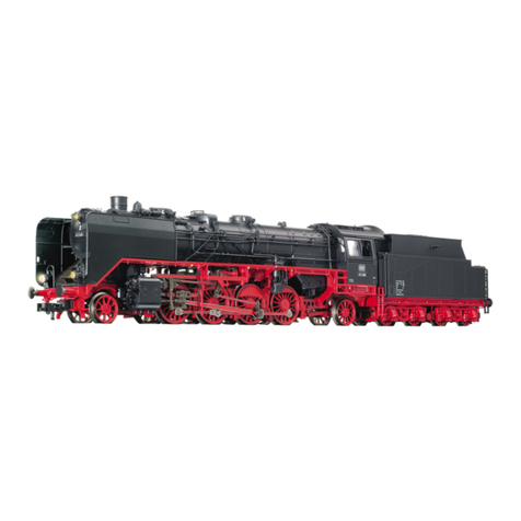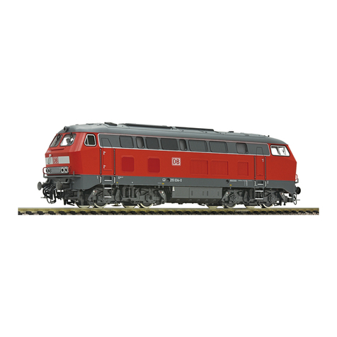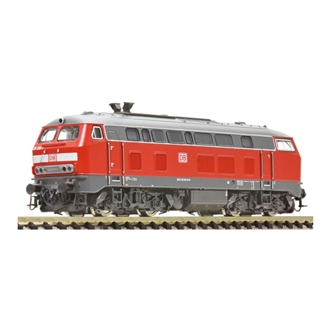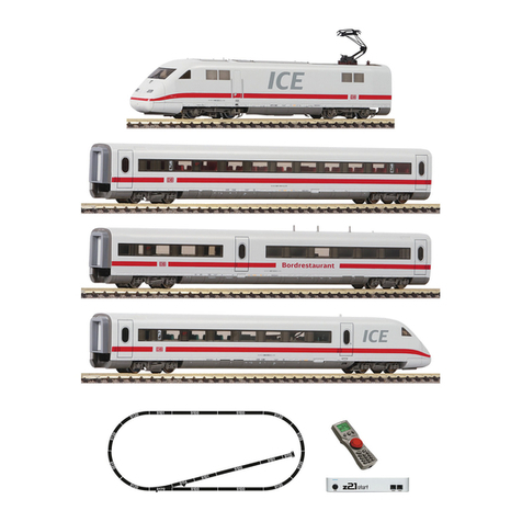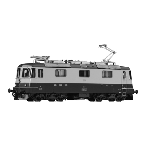
Série 145/146 avec variantes
La série 145 de Deutsche Bahn a été développée à la base de la locomotive électrique 12X de provenanceAdtranz,dont on a aussi repris et adopté la
construction modulaire, que les séries101, 145/146 et 152 ont tous en commun. En s’écartant de la série 101 dont on a repris laconceptiondecer-
tains composantsessentielspour les utiliser pour la série 145, qui débite une puissance de 6400 kW, cette série débite de 4200 kW, elle roule à une vi-
tesse de 140 km/h et elle a une traction de démarrage de 300 kN. Bien qu’elle est assignéeausecteurtransportsdecharge (DB Cargo), elle est aussi
mise en service pour assurer la traction de trains régionaux.
Alimentation par la caténaire: Placer le commutateur en position ”Pantographe“.
Alimentation par les rails: Placer le commutateur en position ”Voies“.
De par la nouvelle conception de traction avec moteur central et transmission par arbres à cardan, les bogies de nouvelles locos ne peuvent
plus être enlevés par le bas, à l’inverse de ce qui se faisait sur les précédentes locos électriques.
Ouverture: L’ouverture de la loco ne se justifie que pour un remplacement de lampes, le remplacement du moteur ou le placement d’un module
récepteur digital. Ecarter les parois de la carrosserie vers son milieu et soulever pour retirer (fig. 3). Lors de la pose du boîter, veiller à ce que le poste
de conduite 1 se trouve côte châssis avec l’encoche réservée au module récepteur digital (hachurée).
Lubrification: Les axes ne seront huilés qu’aux endroits repérés (fig. 5).
N’utilisez que l’huile recommandée FLEISCHMANN 6599. Une seule goutte par point à lubrifier (rt) afin d’éviter tout excès. L’aigulle montée dans le
bouchon du petit flacon convient parfaitement à cet usage. Le moteur ne pourra jamais être lubrifié! Moteur sans entretien!
Remplacement de lampes: retirer, vers le haut, la lampe hors de son logement (fig. 4).
Lampe à incandéscence (blanche): 00006538 (DCC: 00006535) · Lampe à incandéscence (rouge): 00006539 (DCC: 00009531) · Bandages de
rechange: 00544006 · Moteur de remplacement: 00504355
L’aimant permanent 942701 peut étre monté à l’endroit indique (fig. 5).
Cette étoile désigne, le ”côté commun“ de la version la plus courante de la loco (fig. 5).
Les charbons du moteur ne doivent jamais être remplacés!
Déposer du moteur: Oter le boîter de la locomotive par le haut. Dévisser les deux vis (a) et (b) au niveau de la tuyauterie sans les enlever (fig. 7).
Poser la locomotive. Extraire les deux pattes (c) des bogies. Oter le châssis de la locomotive (d) par le haut. Pendant cette opération, les cardans se sé-
parent de leur support situé dans le bogies. La partie tuyauterie et les deux bogies restent solidaires sur la plate-forme. Extraire les 4 pinces (e) vers
l’extérieur (fig. 6). Oter les deux platines (f) et (g). Oter la pince du moteur (h) et retirer le moteur. Extraire les deux cardans jaunes (i) des supporte d’axes.
Poser du moteur: Emboîter les deux cardans jaunes (i) dans les supports d’axes. Placer le moteur sur le châssis de la locomotive. Pendant cette
opération, veiller à la bonne position de motage: le repère noir du moteur doit se trouver côté châssis au niveau de l’encoche pour le module
récepteur digital. Immobiliser le moteur à l’aide de la pince (h). Poser la platine inférieur (courte) (f) et la maintenir en position. Poser ensuite la pla-
tine supérieure (longue) (g) et l’engager dans sa position définitive en veillant à ne pas tordre les lames de contact du moteur. Immobiliser les deux
platines avec les 4 pinces (e). Veillez à ce que les deux cardans jaunes soient orientés vers le bas. Poser le châssis de la locomotive sur les deux bo-
gies en insérant les bogies avec les goupilles (c). Fixer la partie tuyauterie en vissant les vis (a) et (b) et remettre en place le boîter de la locomotive.
Placement d’un module récepteur digital: Un DCC-DECODER 687503 ou 10884 avec 8 pôles (NEM 652) est à coller dans le logement hachuré (j)
existant dans le châssis de la loco (fig. 8). Pour le montage se reporter au mode d’emploi du DECODER.
Attention: En mode DCC il est nécessaire de remplacer les ampoules 00006538 (blanche) et 00006539 (rouge) avec des ampoules 00006535 (blanche)
et 00009531 (rouge).
Changement des attelages: Attelage à embôitement d’autres marques: 6511 · FLEISCHMANN PROFI-Attelage à embôitement: 6515.
1. Retirer dans le sens de la flèche. 2. Replacer le nouvel attelage jusqu’à enclanchement de la buttée.
Bouwserie 145/146 met varianten
De serie 145 van de Deutsche Bahn is een verdere ontwikkeling van eloc 12X van Adtranz. Van dit type werd onder meer de modulaire bouwwijze
overgenomen, die ook in de bouwseries 101, 145/146 en 152 is terug te vinden. In vergelijking met de bouwserie 101 waarvan in principe het bouw-
concept werd overgenomen en die een vermogen heeft van 6400 kW, hebben de locs van de serie 145 een vermogen van 4200 kW en kunnen een
maximum snelheid van 140 km/h halen. Ofschoon deze machines zijn ontworpen om dienst te doen bij DB-Cargo, zullen ze ook voor regionale treinen
worden ingezet.
Stroomtoevoer via de bovenleiding: schakelaar in positie ”pantograaf“ zetten.
Stroomtoevoer via de rails: schakelaar in positie ”rails“ zetten.
Vanwege het nieuwe aandrijfconcept met middenmotor en cardanaandrijving mogen de draaistellen in tegenstelling tot bij andere elektri-
sche locs niet naar onderen worden weggenomen.
Openen: Het openen van de loc is alleen voor het vervangen van de lampjes, de motor en de inbouw van een digitale ontvangerbouwsteen nood-
zakelijk. Lochuis in het midden uit elkaar duwen en naar boven wegnemen (fig. 3). Bij het monteren van et lochuis er op letten dat machinistencabine
1 aan die zijde van het loconderstel wordt geplaatst, waar zich de (gearceerde) uitsparing voor de digitale ontvangerbouwsteen bevindt.
Olien: Alleen de assen op de gekenmerkte plaatsen van olie voorzien (fig. 5). Alleen FLEISCHMANN-olie 6599 gebruiken. Een klein druppeltje per
smeerpunt (rt) is heus voldoende, anders wordt de zaak te vet. Voor een juiste dosering he spuitja gebruiken dat wordt bijgeleverd in het olieflesjes.
De motorlagers mag onder geen beding worden geolied!
Het vervangen van de lampies: Gloeilampje uit de houder naar boven trekken (fig. 4).
Reservelampje (wit): 00006538 (DCC: 00006535) · Reservelampje (rood): 00006539 (DCC: 00009531) · Anti-slip-bandjes: 00544006 · Reserve-
motor: 00504355
Op de gemerkte plaats kan de schakelmagnet 942701 gemonteerd worden (fig. 5).
Dit sterretje betekent dat de loc de ”massa-kant“ aan de gemeenschappelijke zijde heeft (fig. 5).
De sleepcontacten van de motor hoeven niet te worden vervangen!
Het vervangen van de motor: Het lochuis naar boven toe wegnemen. Beide schroeven (a) en (b) aan de onderzijde van de loc losdraaien, maar niet
verwijderen (fig. 7)! De loc neerzetten. Beide stifthouders (c) uit de draaistellen trekken. Het loconderstel (d) naar boven toe wegnemen. Hierdoor ko-
men de gardanassen los van de draaistellen. Het onderstel en beide draaistellen blijven met elkaar verbonden op de ondergrond staan. De vier klem-
houders (e) naar buiten trekken (fig. 6). Beide printplaatjes (f) en (g) verwijderen. Motorhouderklem (h) losnemen en de motor eruit nemen. Beide gele
cardanassen (i) uit de ashouders trekken.
Het inbouwen van de motor: Beide gele cardanassen (i) in de ashouders van de motor klikken. De motor in het loconderstel plaatsen. Let daarbij op
de juiste volgorde: de zwarte motormarkering moet aan die kant van het onderstel liggen, waar zich de uitsparing voor de digitale ontvanger-
bouwsteen bevindt. De motor met behulp van de klemhouder (h) vastzetten. De onderste, korte print (f) plaatsen en vasthouden. Vervolgens de
bovenste, lange print (g) monteren en in de eindstand schuiven. Pas op dat de motorkontakten niet verbuigen! Beide printplaatjes met de vier
klemhouders (e) vastzetten. Let er op, dat beide gele cardanassen naar onderen hangen. Het loconderstel op de draaisteln plaatsen en de cardanas-
sen in de uitsparingen van de draaistellen duwen. De draaistellen met de stifthouders (c) vastzetten. Met beide schroeven (a) en (b) de onderzijde
vastschroeven en het lochuis weer monteren.
Inbouw van een digitale ontvangerbousteen: In de gearceerde uitsparing van het onderstel (j) kan een 8-polige (NEM 652) DCC-DECODER 687503
of 10884 met speciaallijm worden bevestigd (fig. 8). Bij het inbouwen s.v.p. de handleiding van de DECODER raadplegen.
Attentie: In DCC bedrijf, de lampies 00006538 (wit) en 00006539 (rood) worden verfangen door de lampies 00006535 (wit) en 00009531 (rood).
Het verwisselen van de koppeling: Steek-Ruilkoppeling: 6511 ·FLEISCHMANN PROFI-Steekkoppeling: 6515.
1. In de pijlrichting lostrekken. 2. Reservekoppeling in de pijlrichting tot de klemmen pakken.
34.1 A 06/13 21/4324-0102
Litra 145/146 med variante
BR 145 fra DB blev udviklet af Adtranz på basis af ellok 12X. Herfra blev også modulprincippet fra BR 101, 145/146 og 152 overført. I modsætning til
BR 101 yder maskinen 4200 kw, kører 140 km/t og udvikler 300 kn i moment. Selvom maskinen tilhører DB-Cargo, bliver den også anvendt som re-
gionaltog.
Strømtilførsel gennem overledning: Stil kontakten i position ”pantograf“.
Strømtilførsel gennem skinne: Stil kontakten i position ”skinne“.
P.g.a. det nye princip med centermotor og kardanaksler, kan boogierne ikke længere trækkes nedenud.
Åbning: Lokhuset let udad midt på begge sider og løftes ovenud (fig. 3). Vær ved montering af huset opmærksom på, at førerhus 1 monteres på den
side, hvor der i rammen er en udskæring for modtageren.
Smøring: Smør kun aksler på de viste steder (fig. 5). Anvend kun FLEISCHMANN-olie 6599. Kun en enkelt dråbe for hvert smørested (rt), ellers
oversmøres. Til dosering anvendes den ille nål indvendig i skruelåget. Motorlejerne må under ingen omstændigheder smøres!
Pæreudskiftning: Pæren trækkes ovenud af holderen (fig. 3).
Pære (hvid): 00006538 (DCC: 00006535) · Pære (rød): 00006539 (DCC: 00009531) · Friktionsringe: 00544006 · Udskiftningsmotor: 00504355
Kontaktmagneten 942701 kan monteres på det markerde sted (fig. 5).
Denne stjerne betegner den masseførende (stel) ”fælless side“ af lok’et (fig. 5).
Motorens kul skal ikke udskiftes!
Afmontering af motor: Overdelen trækkes ovenud. Begge skruer (a) og (b) på armaturett løsnes, men fjernes ikke (fig. 7). Lok’et stilles til side. Be-
gge holdestifter (c) trækkes ud af boogien. Underdelen (d) løftes ovenud. Derved løsner kardanakslen sig i boogiens skakt. Armaturdelen og begge
boogier bliver stående samlet. De fire holdeklemmer (e) trækkes ud (fig. 6). Begge kontaktplader (f) og (g) fjernes. Motorklemmer (h) løsnes og moto-
ren afmonteres. Begge kardanaksler (i) trækkes ud af holderen.
Indbygning af motoren: Begge kardanaksler (i) klipses på udskiftningsmotorens holdere. Motoren monteres i rammen. Vær opmærksom på
følgende: den sorte markering på motoren skal sidde i samme side af rammen, som udskæringen til modtageren. Holdeklemmer (h) monteres
på motoren. Den nederste korte kontaktplade monteres. Dernæst monteres den lange plade g og skubbes ind på plads. Pas på, at motorens kon-
taktklemmer ikke bøjes! Begge plader sikres med de fire klemmer e. Vær opmærksom på, at de gule kardanaksler kan ses nedefra. Lokrammen
monteres på begge boogier. Kardanakslerne placeres i boogiernes udskaering. Holdestifterne (c) monteres i boogierne. Armaturdelen monteres med
skruerne (a) og (b) og lokhuset monteres til sidst.
Indbygning af digital modtagerenhed: Det er muligt at montere en 8-polede (NEM 652) DCC-DECODER 687503 eller 10884 i motorrammens uds-
kæring (j) (fig. 8). Læs vejledningen ved DECODEREN.
Attention: I drift DCC, den pæren 00006538 (hvid) og 00006539 (rød) skal udskiftes med den pæren 00006535 (hvid) og 00009531 (rød).
Udskiftning af kobling: Stik-udskiftningskobling: 6511 ·FLEISCHMANN PROFI-Stikkobling: 6515.
1. Trækkes ud i pilens retning. 2. Udskiftningskoblingen stikkes i til ”klik“.
Gruppo 145/146 con varianti
La serie 145 della DB è stata originariamente sviluppata dal locomotore 12X della Adtranz, e sulla stessa base è stata realizzata la classe 101,
145/146 e 152. In contrasto con la classe 101 di cui parecchie parti sono state utilizzate per la 145 che ha una potenza di 6400 kW, questo modello ha
una potenza di 4200 kW e una velocità massima di 140 km/h. Nonostante sia stata assegnata al settore traffico merci (DB Cargo), può anche essere
utilizzata per treni regionali.
Alimentazione di corrente tramite linea area: Fessura dell’interruttore in posizione ”linea area“.
Alimentazione di corrente tramite binario: Fessura dell’interruttore in posizione ”binario“.
Con in nuovo sistema di trazione a motore centrale e alberi cardanici i carrelli non possono più essere sfilati dal basso come sulle locomo-
tive elettriche precedenti.
Apertura: L’apertura delle locomotiva si rende necessaria solo per la sostituzione delle lampade o del motore o per l’installazione del modulo di rice-
zione digitale. A tale proposito divaricare lo chassis della locomotiva al centro ed estrario verso l’alto (fig. 3). Durante la sostituzione del mantello fare
attenzione che la cabina del macchinista 1 sia situata a lato del telaio con la cavità (trattegiato) per sitemare il modulo ricevente digitale.
Lubrificazione: Assi devono essere lubrificati solo nei punti appositamente marcati (fig. 5). Utilizzare solo olio FLEISCHMANN 6599. Usare soltanto
una piccola per ogni punto di oliatura (rt), altrimenti si rischia di oliare troppo. Per il dosaggio utilizzare l’ago di cui è provvisto il tappo di chiusura
del flacone dell’olio. Mai lubrificare i cuscinetti del motore!
Sostituzione lampade: Estrarre la lampadina dal portalampada tirandola verso l’alto (fig. 4).
Lampadina di ricambio (bianca): 00006538 (DCC: 00006535) · Lampadina di ricambio (rossa): 00006539 (DCC: 00009531) · Anelli attrito di ri-
cambio: 00544006 · Motor di ricambio: 00504355
Sul posto segnato può essere installato il dispositivo di comando 942701 (fig. 5).
Questo asterisco contrassegna il ”lato comune“ della locomotiva che conduce a massa (fig. 5).
I carboncini del motore non sono sostituibili.
Rimozione del motore: Sollevare il mantello. Svitare entrambe le viti (a) e (b) ma non togliere (fig. 7). Adagiare la loco. Togliere entrambe le spine di
fissagio (c). Sollevare il telaio (d). Questo liberera gli alberi cardanici dalle loro cavità situate nei carrelli. L’armatura e i due carrelli restano uniti nella
parte inferiore. Tirare i quattro fermagli (e) verso l’estreno (fig. 6). Togliere i due circuiti stampati (f) e (g). Svitare i fermagli (h) ed estrarre il motore.
Togliere i due alberi cardanici gialli (i) dai loro supporti.
Installazione del motore: Fermare i due alberi cardanici gialli (i) nei loro supporti. Inserire il motore nel telaio. Fate attenzione a metterlo nella giusta
posizione: il contrassegno nero del motore deve essere posizionato sulla stessa parte terminale del telaio dove c’è spazio per posizionare
il modulo ricevente digitale. Fissare il motore con i fermagli (h). Posare il circuito stampato inferiore (più corto) (f) e per ultimo posare il circuito
stampato superiore (più lungo) (g) e farlo scivolare nella posizione definitiva. Attenzione a non piegare i contatti del motore. Agganciare i due circuiti
stampati nella giusta posizione utilizzando i quattro fermagli (e). Fare attenzione che i due alberi cardanici gialli siano puntati verso il basso. Mettere il
telaio della loco sopra i carrelli assicurandosi che i due alberi cardanici scivolino nella cavità del carrello. Fissare i carrelli in posizione utilizzando la
barra (c). Avvitare l’armatura utilizzando le viti (a) e (b) e risposizionare il mantello della locomotiva.
Installazione del modulo di ricezione digitale: Nell’incavo tratteggiato del carrello della locomotiva (j) può essere incollato un DCC-DECODER
687503 o 10884 à 8 poli (NEM 652) (fig. 8). Per l’installazione seguire le instruzioni del rispettivo DECODER.
Attenzione: In operazione DCC, le lampadine 00006538 (bianca) e 00006539 (rossa) deve essere sostituito con le lampadine 00006535 (bianca) e
00009531 (rossa).
Sostituzione gancio: Gancio di ricambio a innesto: 6511 ·FLEISCHMANN PROFI-Gancio a innesto: 6515.
1. Estrarre in direzione della freccia. 2. Inserire il gancio di ricambio in direzione della freccia fino all’entrata in presa dei morsetti di sostegno.
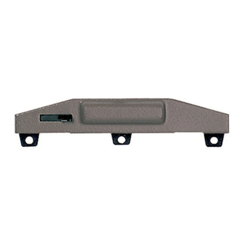
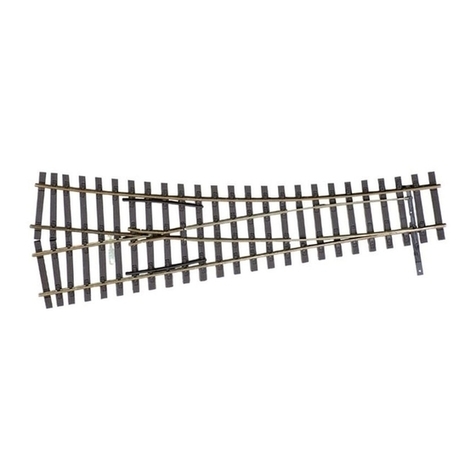
Kontaktgeber in Verbindung mit Schaltschiene 6432 zur Auslösung
elektrischer Schaltfunktionen.
Contacter and contact unit 6432 perform electrical switching func-
tions.
Frotteur fonctionnant e combinaison avec le contact universel
6432 pour effecteur des commandes d’appareils électromagnétiques.
Het kontakt wordt gemaakt tesamen met schakelkontakt 6432 om
de elektrische schakelfunctie buiten werking te stellen.
Kontakt til udløsning af elektriske funktioner – il forbindelse med
kontaktskinne 6432.
Trasmettitore d’impulsi (in unione lamina di condatto 6432) per il co-
mando di dispositivi elettrici.
Schienenreinigung: Bei ungleichmäßigem Lauf von Loks die Schienen
mit Schienenreinigungsgummi 6595 säubern. Abrieb und Staub auf
geeignete Weise entfernen (z. B. Tischstaubsauger). Schienen mit
leicht öligem Lappen nachreiben. Dazu FLEISCHMANN-Öl 6599 ver-
wenden.
Track Cleaning: For smooth running of locos, the tracks must be kept
clean using a track rubber block 6595. Dirt and dust can be removed
in any suitable way (i.e. table vacuum cleaner). Afterwards rub a lightly
oiled rag over the tracks. Use the FLEISCHMANN oil 6599.
Nettoyage des voies : En cas de fonctionnement des locomotives par
”à coups“, nettoyez la voie au moyen de la gomme 6595 prévue à cet
effet. Eliminez au maximum les poussières et autres corps étrangers
(utilisez p. ex. un petit aspirateur ménager). Huilez très parcimonieuse-
ment la vois au moyen d’un chiffon légèrement imbibé d’huile spéciale
FLEISCHMANN 6599.
Rail-reiniging: Bij een ongelijkmatige loop van de locs moeten de rails
met het railreinigingsrubber 6595 worden schoongemaakt. Vuil en
stof daarvan op de bekende wijze wegwerken (bijv. met een stofzu-
igertje). De rails daarna lichtjes met een geolied lapje nabewerken.
Daarvoor FLEISCHMANN-olie 6599 gebruiken.
Skinnerengøring: Hvis toget kører ujævnt p.g.a. snavsede skinner,
bruges gummiblokken 6595. Støv m.v. fjernes, – evt. med en let
støvsugning. Skinnere gnides let over med en blød olieret klud. Brug
FLEISCHMANN olie 6599.
Pulizia delle rotaie: Nel caso di un’andatura irregolare delle locomo-
tive, pulire i binari con la gomma pulisci rotaia 6595. Eliminare segni
di attrito e polvere in modo appropriato (es: con un aspirapolvere da
tavolo). Strofinare le rotaie con un straccio leggermente unto. Allo
scopo utilizzare olio FLEISCHMANN 6599.
Reinigen der Lokräder: Bei Verschmutzung sind die Laufflächen der
Räder mit sauberem Lappen oder Schienenreinigungsgummi 6595
zu reinigen. Niemals die angetriebenen Räder von Hand durchdre-
hen, sondern durch Anlegen einer Fahrspannung mittels An-
schlussdrähten antreiben. Nichtangetriebene Räder können von Hand
gedreht werden.
Diese FLEISCHMANN-Modellok darf nur mit der vorgesehenen Fahr-
spannung (max. 14 V…) betrieben werden. Wir empfehlen die
Verwendung von FLEISCHMANN-Regeltrafos, die mit dem GS-Zei-
chen versehen sind.
Cleaning the Loco Wheels: The running surfaces of the wheels can be
cleaned with a clean rag or by using the track rubber block 6595.
Never turn the driven wheels by hand, only by connecting two wires with
the operating voltage to them. Wheels not driven can be turned by hand.
FLEISCHMANN model railway should only be operated using the cor-
rect voltage (
max. 14 V…
). We recommend the use of FLEISCHMANN
controller/transformers which are marked with the indication GS.
Nettoyage des roues de locomotives : Des roues propres sont le
garant d’un fonctionnement impeccable, éliminez donc les impuretés
sur celles-ci avec un chiffon propre ou la gomme 6595. Ne jamais
faire tourner l’ensemble moteur avec les roues, y appliquez une
tension de service afin de les faire tourner et d’atteindre la cir-
conférence entière de la roue. Les roues non motrices peuvent être
tournées à la main.
Les réseaux FLEISCHMANN ne peuvent être alimentés qu’avec la
tension de service prévue (max. 14 V…
). Nous recommandons les
transformateurs FLEISCHMANN lequels portent la marque d’agréation
GS.
Schoonmaken van de loc-wielen: Als de wielen van de loc vuil zijn
geworden moeten de loopvlakken
met een schone doek of met railrei-
nigingsrubber 6595 worden schoongemaakt. Nooit de aangedreven
assen met de hand doordraaien, maar eventjes aan de trafo aans-
luiten met een rijspanning. De loopassen kunnen natuurlijk gewoon
met de hand worden doorgedraaid.
FLEISCHMANN-modelbanen mogen alleen worden gevoed met de
voorgeschreven gelijkstroomspanning (max. 14 V…). Wij bevelen ge-
bruik van FLEISCHMANN-transformatoren aan, want deze zijn voor-
zien van GS-keuringen.
Rengøring av lok-hjul.: Hvis kørefladerne på hjulene er snavsede,
gøres de rene med en klud eller rummiblokken 6595. Forsøg ikke at
dreje drivhjulene med håndkraft. Vend lok-et på hovedet og hold to
ledninger fra trafoen på hjulene. Drej op for strømmen på transforma-
toren.
Dette tog mu kun anvendes med en jævnstrømtransformator vi anbe-
faler FLEISCHMANNs regulerbare transformatorer (max. 14 V…).
Pulizia delle ruote delle locomotive: In caso di sporcizia le superfici
di attrito delle ruote vanno pulite con uno straccio di lino o con la
gomma pulisci rotaia 6595. Non girare mai le ruote motrici a mano,
ma collegarle a una corrente d’esercizio cavi di collegamento e met-
terle in movimento. Le ruote libere possono essere girate manual-
mente.
I treni in miniatura FLEISCHMANN devono essere azionati soltanto alla
tensione d’esercizio prevista (max. 14 V…). Raccomandiamo
l’impiego di trasformatori di regolazione FLEISCHMANN, i quali sono
forniti di marchi d qualità GS.
6432
6595
Trafo/Fahrregler 6725 · 6735 · 6755
6595
BETRIEBSANLEITUNG
Operating Instructions • Instructions de service •
Handleiding • Vejledning • Istruzione per la manutenzione
Hinweis zur elektromagnetischen Verträglichkeit: Durch einen guten Rad-Schiene-Kontakt vermeiden Sie mögliche elektro-
magnetische Störungen! • Advice about electromagnetic interferences: By having good contact between wheel and rail, any
possible electromagnetic interferences can be avoided! • Conseil pour une parfaite compabilité électro-magnétique: Par un
bon contact électrique ,roues/rails‘, vous éviterez d’éventuelles perturbations électro-magnétiques! • Tip voor elektromagne-
tische zekerheid: Door te zorken voor een goed wiel-rail-kontakt vermijdt u mogelijke elektromagnetische storingen! •
Anvisning på en good elektromagnetisk funktion: Gennem en god hjul-skinne-kontakt undgås eventuelle elektromagnetiske
forstyrrelser! • Consiglio sulla compatibilià elettromagnetica: Per un buon contatto ruota-rotaia evitare possibili interferenze
elettromagnetiche! • Recomendacion para un mejor funcionamiento electromagnetico: Con un buen contacto entre las vias
y las ruedas evitara usted irregularidades electromagneticas!
GEBR. FLEISCHMANN GMBH & CO. KG
D-91560 Heilsbronn, Germany
www.fleischmann.de
14 V
(bei Gleich-
strombetrieb)
Fig. 1
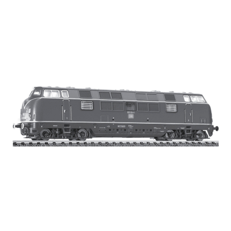
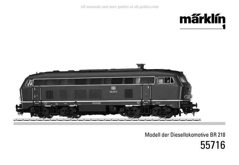
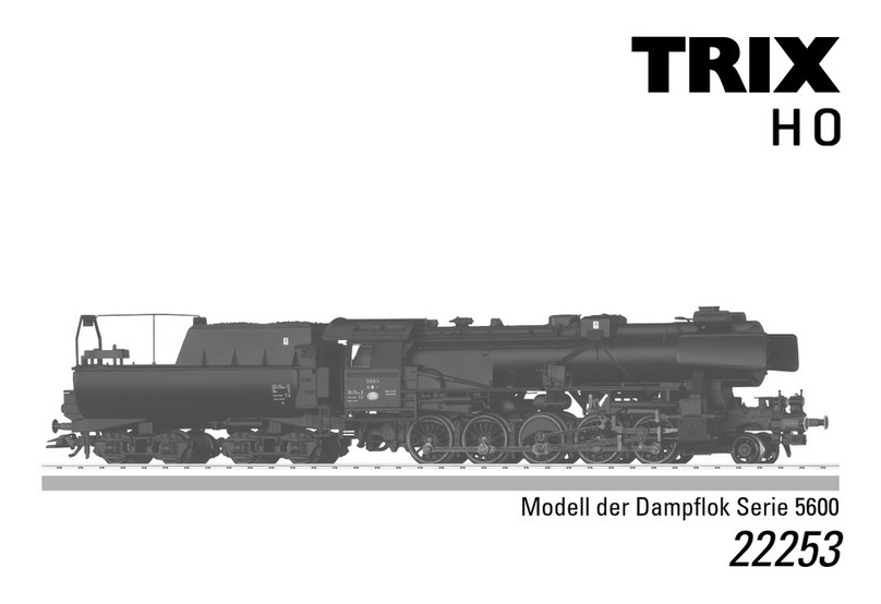
Die Baureihe 145 der Deutschen Bahn (Fig. 1) wurde aus der Ellok 12X von Adtranz entwickelt. Von dieser Type
wurde auch die Modulbauweise, welche die Baureihen 101, 145/146 und 152 verbindet, übernommen. Gegenüber
der Baureihe 101, von der konzeptionell einige wichtige Bauteile für die Baureihe 145 verwendet wurden und die
6400 kW Leistung abgibt, leistet sie 4200 kW, fährt 140 km/h schnell und entwickelt eine Anfahrzugkraft von 300
kN. Obwohl sie zum Geschäftsbereich Ladungsverkehr (DB-Cargo) gehört, ist sie auch für die Traktion von
Regionalzügen vorgesehen.
Baureihe 145/146 mit Varianten
NEM
21-4324-0102.indd 1-4 04.06.2013 13:36:37


