FLIR MR160 USER MANUAL Document Identifier: MR160-en-US_AF
5. Operation
Important Note: Please charge the meter’s battery before first use. Instructions for battery
charging are provided in Section 6.2.
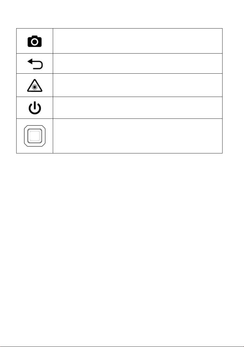
5.1 Powering the Meter
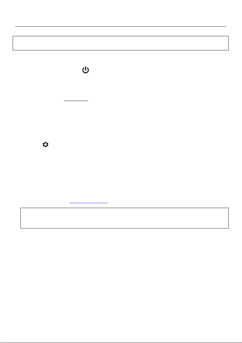
1. Press the Power button momentarily to switch the meter ON.
2. Press and hold the Power button for > 1 second to switch the meter OFF.
3. If the battery status indicator shows that the battery voltage is low, or if the meter does not
power on, charge the battery. See section 6.2 Battery Charging. The battery status indicator
is visible in the Main Menu (press the center Select button to access the Main Menu).
4. Please fully charge the battery before use.
5.1.1 Auto Power OFF (APO)
The meter switches OFF automatically after a programmed period of inactivity. Press any
button to reset the APO timer. To disable APO, or to change the APO time-out value, use the
Settings mode, accessible from the Main Menu. The default time-out is 20 minutes.
5.2 Moisture Measurements
5.2.1 Moisture Measurement Overview
Moisture measurements can be performed using either the internal pinless moisture sensor
(rear) or by connecting an external probe. A standard external pin probe is included which
connects to the MR160 via the jack at the bottom of the meter. Other external probes are
available; please visit www.flir.com/test for details.
NOTE: Objects near the internal pinless moisture sensor (located on the rear of the unit) will
affect the reading on the display; Keep hands and fingers clear of the sensor when taking
measurements.
The internal moisture sensor detects moisture to a depth of approximately 19mm (0.75”). The
actual depth will vary depending upon the amount of moisture, the material under test, surface
roughness, and other factors.
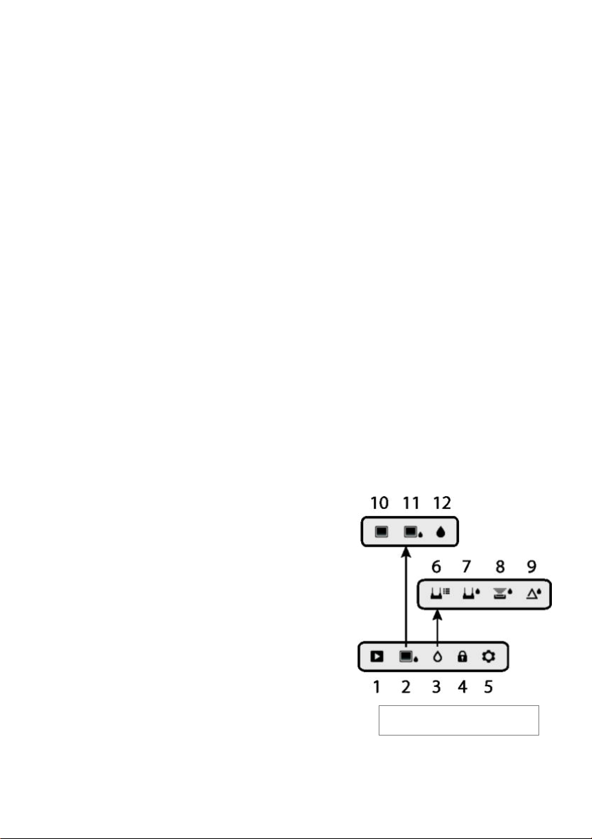
Moisture readings are shown on the display (digitally and with bar graph) in the Moisture-only
mode or in small digits (upper left-hand corner) in the IR + IGM Moisture mode. See Fig. 5-1.
Pinless measurement readings are ‘relative’scaled (0~100). Pin-based readings are represented
in terms of %MC (moisture content) for wood and %WME (wood moisture equivalent) for non-
wood materials; additional information is provided in Section 5.2.6 External Pin Probe Moisture
Measurements and in the specifications.
Moisture measurements are covered in detail in the following sections. Be sure to select Pin
Mode or Pinless Mode in the Moisture Menu to match the measurement type.