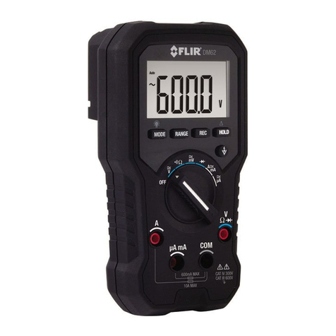
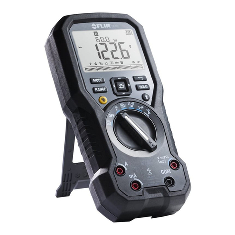
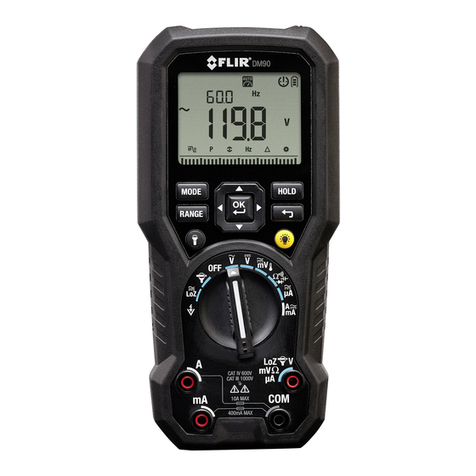
FLIR DM91 User manual

USER MANUAL
FLIR MODEL DM91
True RMS Industrial Multimeter with Bluetooth®

FLIR DM91 USER MANUAL Document Identifier: DM91-en-US_AB
2
Table of Contents
1. ADVISORIES 4
1.1 Copyright 4
1.2 Quality Assurance 4
1.3 Documentation 4
1.4 Disposal of Electronic Waste 4
2. SAFETY 5
3. INTRODUCTION 7
3.1 Key Features 7
4. METER DESCRIPTION 8
4.1 Front and Back Descriptions 8
4.2 Function Switch Positions 9
4.3 Function Buttons and Selector/Navigation Pad 10
4.3.1 MODE Button Operation 10
4.3.2 Selector/Navigation Pad Operation 11
4.4 Display Description 11
4.5 Display Icons and Indicators 12
4.5.1 Probe Detection Alert 13
4.5.2 Out-of-range warning 13
4.6 Mode Menu Bar Basics 14
5. OPERATION 15
5.1 Powering the Meter 15
5.1.1 Auto Power Off (APO) 15
5.2 Auto/Manual Range Mode 15
5.3 Voltage and Frequency Measurements 16
5.4 Resistance Measurements 17
5.5 Continuity Test 17
5.6 Classic Diode Test 18
5.7 Smart Diode Test 19
5.8 Capacitance Measurements 20
5.9 Type K Temperature Measurements 21
5.10 Current and Frequency Measurements 22

FLIR DM91 USER MANUAL Document Identifier: DM91-en-US_AB
3
5.10.1 Test Lead Current Measurements (A, mA, and µA) 22
5.10.2 FLEX Clamp Adaptor Current Measurements 25
5.11 Non-Contact Voltage Detector 26
6. MENU BAR FOR EXTENDED FUNCTIONALITY 27
6.1 Selecting Modes using the Menu Bar 27
6.2 VFD Mode (ACV and ACA only) 27
6.3 Peak Mode (ACV and ACA only) 27
6.4 Min/Max/Avg Mode 27
6.5 Frequency mode (ACV and ACA only) 28
6.6 Relative mode 28
6.7 Datalogger 28
6.8 Settings Menu 29
6.9 Data Hold and Auto Hold 30
6.9.1 Data Hold Mode 30
6.9.2 Auto Hold Mode 30
7. BLUETOOTH® COMMUNICATION AND FLIR TOOLSTM 31
8. MAINTENANCE 32
8.1 Cleaning and Storage 32
8.2 Battery Replacement 32
8.3 Fuse Replacement 32
8.4 Disposal of Electronic Waste 32
9. SPECIFICATIONS 33
9.1 General specifications 33
9.2 Electrical Range Specifications 34
10. TECHNICAL SUPPORT 39
11. WARRANTY 40

FLIR DM91 USER MANUAL Document Identifier: DM91-en-US_AB
4
1. Advisories
1.1 Copyright
© 2019, FLIR Systems, Inc. All rights reserved worldwide. No parts of the software
including source code may be reproduced, transmitted, transcribed or translated into
any language or computer language in any form or by any means, electronic, magnetic,
optical, manual or otherwise, without the prior written permission of FLIR Systems.
The documentation must not, in whole or part, be copied, photocopied, reproduced,
translated or transmitted to any electronic medium or machine readable form without
prior consent, in writing, from FLIR Systems.
Names and marks appearing on the products herein are either registered trademarks or
trademarks of FLIR Systems and/or its subsidiaries. All other trademarks, trade names or
company names referenced herein are used for identification only and are the property
of their respective owners.
1.2 Quality Assurance
The Quality Management System under which these products are developed and
manufactured has been certified in accordance with the ISO 9001 standard.
FLIR Systems is committed to a policy of continuous development; therefore, we reserve
the right to make changes and improvements on any of the products without prior
notice.
1.3 Documentation
To access the latest manuals and notifications, go to the Download tab at:
http://support.flir.com. It only takes a few minutes to register online. In the download
area you will also find the latest releases of manuals for our other products, as well as
manuals for our historical and obsolete products.
1.4 Disposal of Electronic Waste
As with most electronic products, this equipment must be disposed of in an
environmentally friendly way, and in accordance with existing regulations for
electronic waste.
Please contact your FLIR Systems representative for more details.

FLIR DM91 USER MANUAL Document Identifier: DM91-en-US_AB
5
2. Safety
Safety Notes
•Before operating the device, you must read, understand, and follow all instructions,
dangers, warnings, cautions, and notes.
•FLIR Systems reserves the right to discontinue models, parts or accessories, and other
items, or to change specifications at any time without prior notice.
•Remove the batteries if the device is to be idle for an extended period.
Warning Statements
•Do not operate the device if you do not have the correct knowledge. Incorrect operation
of the device can cause damage, shock, injury or death to persons.
•Do not start a measuring procedure before you have set the function switch to the
correct position. Failure to do so can cause damage to the instrument and can cause
injury to persons.
•Do not change to the resistance mode when measuring voltage. This can cause damage
to the instrument and can cause injury to persons.
•Do not measure the current on a circuit when the voltage increases to more than 1000 V.
This can cause damage to the instrument and can cause injury to persons.
•You must disconnect the test leads from the circuit under test before you change the
range. Failure to observe this warning can damage the instrument and cause bodily
injury.
•Do not replace the batteries before you remove the test leads. This can cause damage to
the instrument and can cause injury to persons.
•Do not use the device if the test leads and/or the device show signs of damage. Injury to
persons can occur.
•Be careful performing measurements if the voltages are > 25 VAC rms or 35 VDC. There is
a risk of shock from these voltages. Injury to persons can occur.
•Do not do diode, resistance or continuity tests before you have removed the power from
capacitors and other devices under test. Injury to persons can occur.
•Be careful when performing voltage checks on electrical outlets. These checks are
difficult because of the uncertainty of the connection to the recessed electrical contacts.
You must not rely solely on this this device when determining if the terminals are not
“live”. There is a risk of electrical shock. Injury to person can occur.
•Do not touch expired/damaged batteries without gloves. Injury to persons can occur.
•Do not cause a short circuit of the batteries. This can cause damage to the instrument
and can cause injury to persons.
•Do not put the batteries into a fire. Injury to persons can occur.
FLIR DM91 USER MANUAL Document Identifier: DM91-en-US_AB
6
Cautions
Do not use the device in a manner not specified by the manufacturer. This can cause damage to
the protection provided.
This symbol, adjacent to another symbol or terminal, indicates that the user
must refer to the user manual for further information.
This symbol, adjacent to a terminal, indicates that, under normal use, hazardous
voltages may be present.
Double insulation.
UL listing is not an indication or a verification of the accuracy of the meter

FLIR DM91 USER MANUAL Document Identifier: DM91-en-US_AB
7
3. Introduction
Thank you for selecting the FLIR DM91 True RMS Digital MultiMeter with Bluetooth®,
Type-K thermocouple, automatic datalogging, and work light features. The DM91 can
measure voltage up to 1000V AC/DC and includes Low-Z (low impedance), VFD (low
pass filter), Non-Contact Voltage Detector, and Smart/Classic Diode modes. This device
is shipped fully tested and calibrated and, with proper use, will provide years of reliable
service.
3.1 Key Features
•6000 count 2.8” digital LCD display with bargraph
•Measures Voltage, Current (A, mA, µA), Frequency, Resistance/Continuity,
Diode, Capacitance, Non-Contact Voltage, and Temperature
•Bluetooth® communication allows readings to be viewed on remote devices
•Customizable via easy-to-use Settings menu with on-screen menu navigation
•Automatic and Manual ranging
•Input over-voltage warning
•Automatic datalogging for up to 40,000 readings
•MIN-MAX-AVG memory
•PEAK MIN and PEAK MAX
•Flex Clamp direct input
•CLASSIC and SMART Diode modes
•Variable-frequency drive VFD mode (low-pass filter)
•Low-Z (low impedance) mode
•Relative mode
•Data Hold and Auto Hold
•Auto Power OFF
•Real-time calendar clock
•Safety Category Rating: CAT IV-600V, CAT III-1000V
•Equipped with batteries, test leads, alligator clips, test lead storage attachment,
Type-K thermocouple, and Quick Start Guide.

FLIR DM91 USER MANUAL Document Identifier: DM91-en-US_AB
8
4. Meter Description
4.1 Front and Back Descriptions
Fig. 4-1 Front View
1. Work Light and NCV Detector
2. LCD Display
3. Navigation/OK buttons
4. MODE Button
5. RANGE Button
6. Work light Button
7. Rotary Function Switch
8. Positive (+) Probe Input Jack for A
(Current).
9. Positive (+) Probe Input Jack for
mA (Current).
10. COM (-) Probe Input Jack
11. Positive (+) Probe Input Jack for
all inputs except Aand mA
12. Display Backlight Button
13. Cancel/Return Button
14. Display HOLD Button
1. Test Lead holder attachment mounts
2. Tripod mount (test lead holder attaches here also)
3. Tilt Stand (Battery Compartment located beneath
the stand)
Fig. 4-2 Rear View

FLIR DM91 USER MANUAL Document Identifier: DM91-en-US_AB
9
4.2 Function Switch Positions
Detect AC voltage through the non-contact sensor at the top of the meter.
Measure voltage through the probe inputs with a low-impedance load
positioned across the inputs that stabilizes the measurement.
FLEX Direct: Auxiliary channel for use with optional Flexible Current clamp or
standard clamp adaptors when > 600A measurements are required. In this
mode, the meter will display true rms ACA measurements from the connected
device. Frequency (Hz) appears when the MODE button is pressed.
Meter is OFF and in full power-saving mode.
Measure AC voltage (V) through the probe inputs.
Measure DC voltage (V) through the probe inputs.
Measure low voltage (mV) through the probe inputs. Use the MODE button to
select AC/DC voltage.
Measure temperature through the probe inputs using a thermocouple
adaptor. Use the MODE button to select Temperature (see Section 6.8,
Settings Menu, to select °C or °F as the default unit).
Measure resistance, continuity, capacitance, or diode through the probe
inputs. Use the MODE button to select the desired function.
Measure µA current through the probe inputs. Use the MODE button to select
AC or DC.
Measure current through the probe inputs (A or mA). Use the MODE button to
select AC or DC.
Fig. 4-3 Function Switch

FLIR DM91 USER MANUAL Document Identifier: DM91-en-US_AB
10
4.3 Function Buttons and Selector/Navigation Pad
Use to select a sub-function of the primary function. See Section 4.3.1, MODE
Button Operation, for details.
From Auto range mode, press to select Manual range mode.
From Manual range mode, press < 1 second to change the range (scale). Press
> 1 second to activate Auto range mode
Press to toggle between Hold mode and normal display mode. Use the Settings
menu (see Section 6.8, Settings Menu) to select Data hold or Auto hold.
Use the selector/navigation pad to enable extended functionality modes and
to navigate mode menu options.
Press to cancel/exit a screen in the Settings menu (no function in the normal
mode).
Press to enable/disable the display backlight. The backlight’s default state is
ON.
Press to switch the work light ON or OFF.
4.3.1 MODE Button Operation
Switch Position
MODE button sequence of operation
AC → DC → °F or °C
Resistance → Continuity → Capacitance → Diode
AC → DC
AC → DC

FLIR DM91 USER MANUAL Document Identifier: DM91-en-US_AB
11
4.3.2 Selector/Navigation Pad Operation
There are five (5) ‘soft’ Function buttons arranged in a square, as shown in Figure 4-4.
The function of these buttons changes, depending on the menu-driven sub-function
selected.
Fig. 4-4 Selector Navigation Pad
Pressing the OK button (center) selects a menu-driven option. The OK button also
accesses further into the sub-menus of selection screens.
The LEFT/RIGHT buttons:
In normal mode, the left/right buttons move the menu cursor
In Settings mode, the left/right buttons change the value of an option
The UP/DOWN buttons:
In normal mode, the up/down buttons have no function
In Settings mode, the up/down buttons change an option.
4.4 Display Description
Fig. 4-5 Display Icons (see Section 4-5 for descriptions)

FLIR DM91 USER MANUAL Document Identifier: DM91-en-US_AB
12
4.5 Display Icons and Indicators
1
Measured voltage is > 30 V (AC or DC)
2
Non-Contact Voltage detector
3
FLEX Clamp adaptor input
4
Low Impedance mode
5
MAX (Maximum), MIN (minimum), and AVG (Average) readings
PEAK MAX and PEAK MIN readings
6
Auto range mode
7
Data Hold mode
8
Work light active
9
Bluetooth® active icon (see Section 7, Bluetooth® Communication)
10
Auto power off function enabled
11
Battery voltage status
12
Flex Clamp Direct Input
13
Primary display (large digits) with units of measure
14
MENU BAR ICON: Settings mode

FLIR DM91 USER MANUAL Document Identifier: DM91-en-US_AB
13
15
MENU BAR ICON: Automatic Datalogging mode
16
MENU BAR ICON: Relative mode
17
MENU BAR ICON: Frequency mode
18
MENU BAR ICON: MAX-MIN-AVG mode
19
MENU BAR ICON: Peak MAX / Peak MIN mode
20
Bar Graph Measurement Indicator
21
MENU BAR ICON: VFD mode (see Section 4.6, Menu Icon Bar)
22
Diode test function
23
Continuity function
24
Minus sign (positive assumed)
25
DC Voltage or Current
26
AC Voltage or Current
27
Secondary display (smaller digits) with units of measure
28
Menu display prompt informing user to use the up/down buttons
4.5.1 Probe Detection Alert
For current measurements (A and mA), when the test leads are not plugged into the
correct jacks for the measurement selected by the function switch, the probe display
alert ‘Prob’is shown.
4.5.2 Out-of-range warning
If the input is over/under the full-scale range in Manual range mode, or if the signal has
exceeded the maximum/minimum input in Auto range mode, ‘OL’is displayed.

FLIR DM91 USER MANUAL Document Identifier: DM91-en-US_AB
14
4.6 Mode Menu Bar Basics
There are seven (7) Menu Bar functions represented by the following icons. Refer to
Section 6, Mode Menu Bar for Extended Functionality for further explanation on these
functions.
VFD (low pass filtering)
Peak Max and Peak Min (Auto Hold)
MAX-MIN-AVG memories
Frequency measurements
Relative mode
Automatic Datalogging mode
Settings mode
1. Only one icon flashes at a time to indicate the cursor position.
2. Use the Left / Right buttons to move the cursor.
3. Press the OK button to activate / deactivate the selected function. The LCD will
show a frame around activated functions (even when the cursor is steered away
from the icon).
4. In the AC Voltage/AC mV/AC Current/Flex/Lo Z modes all icons shown above are
available (the exception is that the Hz function is not available in the mode).
5. For DC Current/Voltage, Resistance, Continuity, Capacitance, Temperature, and
Diode only the MAX-MIN-AVG, Relative, Datalogger, and Settings icons are
available.

FLIR DM91 USER MANUAL Document Identifier: DM91-en-US_AB
15
5. Operation
Caution: Before operating the device, you must read, understand, and follow all
instructions, dangers, warnings, cautions, and notes.
Caution: When the meter is not in use, the function switch should be set to the OFF
position.
Caution: When connecting the probe leads to the device under test, connect the COM
(negative) lead before connecting the positive lead. When removing the probe leads,
remove the positive lead before removing the COM (negative) lead.
5.1 Powering the Meter
1. Set the function switch to any position to switch on the meter.
2. If the battery indicator shows that the battery voltage is low or if the meter does not
power on, replace the batteries. See Section 8.2, Battery Replacement.
5.1.1 Auto Power Off (APO)
The meter enters sleep mode after a programmable period of inactivity, see Section
6.8, Settings Menu. The default time-out is 20 minutes. The time can be set from 1 ~ 30
minutes (select OFF to disable the APO). 20 seconds prior to entering APO mode, the
meter beeps three times; at this point, press any button or turn the Rotary Switch to
reset the APO timer.
5.2 Auto/Manual Range Mode
In Auto range mode, the meter automatically selects the most appropriate measurement
scale. In Manual range mode, the user selects the desired range (scale).
Auto range mode is the default mode of operation. When you select a new function with
the function switch, the starting mode is Auto range and the indicator appears.
1. To enter Manual range mode, short press the button. To change the
range, press the button repeatedly until the desired range appears.
2. To return to the Auto range mode, long press the button until the Auto
Range indicator again appears.

FLIR DM91 USER MANUAL Document Identifier: DM91-en-US_AB
16
5.3 Voltage and Frequency Measurements
1. Refer to the Fig. 5-1 below.
2. Set the function switch to one of the following positions:
•(VDC) or (VAC) for high voltage measurements.
•(milli-volts) for low voltage measurements (use MODE to select AC or
DC).
•for voltage measurements using the meter’s low input impedance
mode. The LoZ indicator will be displayed (use to select AC or DC).
3. Insert the black probe lead into the negative COM terminal and the red probe
lead into the positive terminal.
4. For mV and LoZ measurements use the button to select AC or DC
measurement:
•The indicator shows for AC measurements.
•The indicator shows for DC measurements.
5. Connect the probe leads in parallel to the part under test.
6. Read the voltage value on the display.
7. For AC Voltage Measurements, the Frequency (Hz) of the measured voltage
appears on the smaller, secondary display digits above the primary voltage
reading. To display only the Frequency, navigate to the menu icon using the
arrow buttons and enable (or disable) the mode by pressing OK.
Fig. 5-1 Voltage and Frequency Measurements

FLIR DM91 USER MANUAL Document Identifier: DM91-en-US_AB
17
5.4 Resistance Measurements
Warning: Do not perform diode, resistance or continuity tests before removing power
from capacitors and other devices under test during a measurement. Injury to persons
can occur.
1. Refer to Fig. 5-2. Set the function switch to the position.
2. Use to step to the Ωdisplay if necessary.
3. Insert the black probe lead into the negative COM terminal and the red probe
lead into the positive Ωterminal.
4. Touch the tips of the probe across the circuit or component under test.
5. Read the resistance value on the display.
5.5 Continuity Test
Warning: Do not perform diode, resistance or continuity tests before removing the
power from capacitors and other devices under test during a measurement. Injury to
persons can occur.
1. Refer to Fig. 5-2. Set the function switch to the position.
2. Use the button to select continuity. The indicator will appear.
3. Insert the black probe lead into the negative COM terminal and the red probe
lead into the positive terminal.
4. Touch the tips of the probe across the circuit or component under test.
5. If the resistance is < 20Ω the meter beeps. If the resistance is > 200Ω the meter
will not beep. If the resistance is > 20Ω but < 200Ω the beeping will stop at an
unspecified point.
Fig. 5-2 Resistance and Continuity Measurements

FLIR DM91 USER MANUAL Document Identifier: DM91-en-US_AB
18
5.6 Classic Diode Test
Warning: Do not perform diode tests before removing the power to the diode or other
devices under test during a measurement. Injury to persons can occur.
1. If not already selected, choose CLASSIC Diode test mode in the Settings menu
(see Section 6.8, Settings Menu).
2. Set the function switch to the diode position. Use the button to
select the diode test function. The diode indicator appears.
3. Insert the black probe lead into the negative COM terminal and the red probe
lead into the positive terminal.
4. Touch the tips of the probe across the diode or semiconductor junction under
test in one polarity (direction) and then in the opposite polarity as shown in Fig.
5-3.
5. If the reading is between 0.400 and 0.800V in one direction and OL (overload) in
the opposite direction, the component is good. If the measurement is 0V in both
directions (shorted) or OL in both directions (open), the component is bad.
Fig. 5-3 Classic Diode Measurements

FLIR DM91 USER MANUAL Document Identifier: DM91-en-US_AB
19
5.7 Smart Diode Test
Warning: Do not perform diode tests before removing the power from capacitors and
other devices under test during a measurement. Injury to persons can occur.
1. If not already selected, choose SMART Diode test mode in the Settings menu
(see Section 6.8, Settings Menu).
2. Set the function switch to the diode position. Use the button to
select the diode test function. The diode indicator appears.
3. Insert the black probe lead into the negative COM terminal and the red probe
lead into the positive terminal.
4. Touch the tips of the probe across the diode or semiconductor junction under
test.
5. If the reading is between ± 0.400 ~ 0.800V, the component is good; BAD or O.L
displays indicate a defective component.
NOTES: In SMART Diode mode the meter checks diodes using an alternating test
signal sent through the diode in both directions. This allows the user to check the
diode without having to reverse polarity manually. The meter display will show ±
0.400 ~ 0.800V for a good diode, ‘bAd’ for a shorted diode, and ‘O.L’for an opened
diode. See Fig. 5.4 below:
Fig. 5-4 SMART Diode Test

FLIR DM91 USER MANUAL Document Identifier: DM91-en-US_AB
20
5.8 Capacitance Measurements
Warning: Do not perform capacitance tests before removing the power to the capacitor
or other devices under test during a measurement. Injury to persons can occur.
1. Set the function switch to the position.
2. Use the button to select the capacitance measurement. The F (Farad) unit
of measure appears.
3. Insert the black probe lead into the negative COM terminal and the red probe
lead into the positive terminal.
4. Touch the tips of the probe across the part under test.
5. Read the capacitance value on the display.
Note: For very large capacitance values, it may take several minutes for the
measurement to settle and the final reading to stabilize.
Fig. 5-5 Capacitance Measurements
Table of contents
Other FLIR Multimeter manuals

FLIR
FLIR DM93-2 User manual

FLIR
FLIR EXTECH INSTRUMENTS MA120 User manual

FLIR
FLIR Extech Instruments MultiMaster MM560A User manual

FLIR
FLIR Extech Instruments MN15 User manual

FLIR
FLIR Extech Instruments 380941 User manual

FLIR
FLIR DM93-2 User manual

FLIR
FLIR DM284 User manual

FLIR
FLIR DM93 User manual

FLIR
FLIR MR160 User manual

FLIR
FLIR DM90 User manual

FLIR
FLIR DM92 User manual

FLIR
FLIR Extech Instruments MG302 User manual

FLIR
FLIR Extech Instruments MN16 User manual

FLIR
FLIR DM285 User manual

FLIR
FLIR DM284 User manual

FLIR
FLIR DM90 User manual

FLIR
FLIR DM6 Series User manual

FLIR
FLIR DM93 User manual

FLIR
FLIR EXTECH INSTRUMENTS EX520 User manual

FLIR
FLIR DM90 User manual