flowair slim Series User manual

1

2
TECHNICAL DOCUMENTATION: EN
TABLE OF CONTETNS
1. IMPORTANT INFORMATION............................................................................................................................................ 3
2. GENERAL INFORMATION ................................................................................................................................................ 4
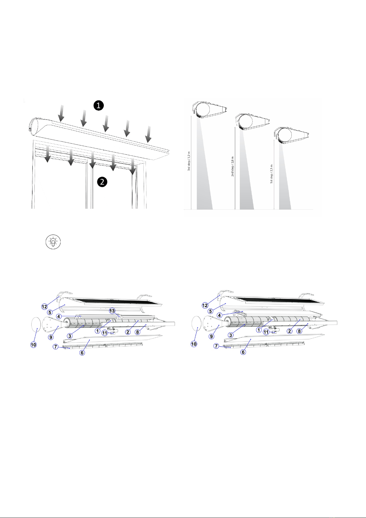
3. CONSTRUCTION............................................................................................................................................................... 4
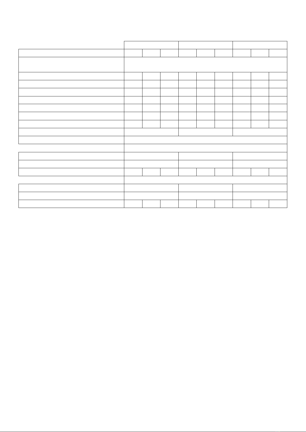
4. TECHNICAL DATA SLIM N/W ........................................................................................................................................... 5
5. TECHNICAL DATA SLIM E ................................................................................................................................................ 6
6. DIMENSIONS INFORMATION .......................................................................................................................................... 7
7. INSTALATION INFORMATION......................................................................................................................................... 7
8. MOUNTING - RECOMMENDED DISTANCES INFORMATION........................................................................................... 8
9. MOUNTING - CEILING MOUNTING INSTALLATION WITH THREADED RODS INFORMATION....................................... 8
10. MOUNTING WITH BRACKETS ....................................................................................................................................... 9
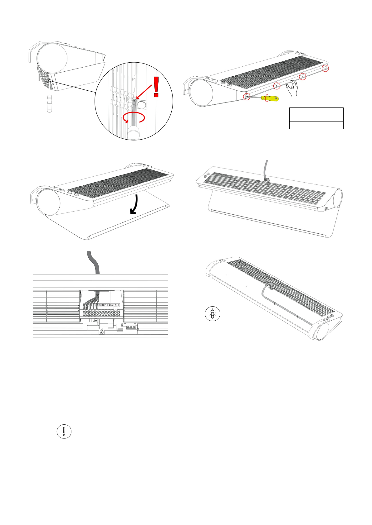
11. CONNECTION OF ELECTRICAL INSTALALTION .......................................................................................................... 10
12. BUILT-IN CONTROL...................................................................................................................................................... 11
13. BUILT-IN CONTROL – CONNECTION DIAGRAM SLIM E.............................................................................................. 12
14. BUILT-IN CONTROL – CONNECTION DIAGRAM SLIM W; SLIM N ............................................................................... 13
15. CONTROLS - OPTIONAL ELEMENTS............................................................................................................................ 14
16. ADJUSTMENT OF OUTLET GRILLE .............................................................................................................................. 14
17. CONNECTION OF HYDRAULIC INSTALLATION........................................................................................................... 15
18. PARAMETERS OF THE HEATING MEDIUM .................................................................................................................. 15
19. FILTER INSTALLATION................................................................................................................................................. 16
20. OPERATON................................................................................................................................................................... 16
21. CLEANING AND MAINTENANCE ................................................................................................................................. 16
22. COMPLIANCE WITH WEEE 2009/19/EC....................................................................................................................... 17
23. CONFORMITY WITH WEEE DIRECTIVE 2012/19/UE ................................................................................................... 17
24. SERVICE AND WARRANTY TERMS .............................................................................................................................. 17
DOKUMENTACJA TECHNICZNA: PL
SPIS TREŚCI
1. WAŻNE INFORMACJE................................................................................................................................................19
2. INFORMACJE OGÓLNE..............................................................................................................................................20
3. BUDOWA ...................................................................................................................................................................20
4. DANE TECHNICZNE SLIM N/W...................................................................................................................................21
5. DANE TECHNICZNE SLIM E........................................................................................................................................22
6. WYMIARY...................................................................................................................................................................23
7. MONTAŻ....................................................................................................................................................................23
8. MONTAŻ–ZALECANE ODLEGŁOŚCI.........................................................................................................................24
9. MONTAŻZA POMOCĄSZPILEK GWINTOWANYCH..................................................................................................24
10. MONTAŻZA POMOCĄWSPORNIKÓW .....................................................................................................................25
11. PODŁĄCZENIE INSTALACJI ELEKTRYCZNEJ.............................................................................................................26
12. STEROWANIE WBUDOWANE ....................................................................................................................................27
13. STEROWANIE WBUDOWANE -SCHEMAT PODŁĄCZENIA SLIM E ............................................................................28
14. STEROWANIE WBUDOWANE -SCHEMAT PODŁĄCZENIA SLIM W; SLIM N..............................................................29
15. STEROWANIE-OPCJONALNE ELEMENTY ................................................................................................................30
16. REGULACJA KRATKI WYLOTOWEJ............................................................................................................................30
17. PODŁĄCZENIE INSTALACJI HYDRAULICZNEJ..........................................................................................................31
18. PARAMETRY CZYNNIKA GRZEWCZEGO...................................................................................................................31
19. MONTAŻFILTRA........................................................................................................................................................32
20. EKSPLOATACJA.........................................................................................................................................................32
21. CZYSZCZENIE IKONSERWACJA................................................................................................................................32
22. ZGODNOŚĆZDYREKTYWĄ2009/125/WE................................................................................................................33
23. ZGODNOŚĆ ZDYREKTYWĄWEEE 2012/19/UE ........................................................................................................33
24. KARTA GWARANCYJNA ............................................................................................................................................35

3
TECHNICAL DOCUMENTATION: EN
1. IMPORTANT INFORMATION
We have made every effort to make this manual as easy to understand as possible. However, if you have any difficulties, problems
or questions, please contact FLOWAIR support at: info@flowair.pl
Also visit our website www.flowair.pl where you will find mounting tips.
In this manual you will find important safety information and tips marked as below:
WARNING
• Dangerous practices which may
result in serious injury or death.
Read all warnings before
starting work.
CAUTION
• unsafe practices which, if not
avoided, may result in damage
to property or minor injuries.
Before starting work, read all
cautions.
ADVICE
• Useful tips for the user and
installer.
IMPORTANT SAFETY INFORMATION:
ADVICE
1. Before installing, connecting, starting up, using and maintaining the device, please read this manual
completely.
2. After receiving the product, check that it has not been damaged during transport. If the product appears to be
damaged, DO NOT START TO MOUNT THE DEVICE; instead, you must immediately report the damage to the
carrier.
3. The device must be mounted in a stable way and in accordance with the instructions, in a place that can be
easily accessed, thus ensuring the possibility of carrying out repairs and routine maintenance, as well as allowing
easy and safe disassembly of the device.
4. The stability and durability of installation of the device depends on the structure of the building (in particular
walls and ceilings). The person performing the assembly should take these conditions into account when
mounting the device.
5. The technical documentation should be kept in a safe place, easily accessible to the user and service
technician.
6. The nameplate is located next the cable glands on the top of the device.
7. Always test the operation of the device after installation.
CAUTION
1. The power connection shall be performed only by an authorized person.
2. The device may start automatically (when motion is detected in the sensor area).
3. The device is not equipped with a thermostat that controls the room temperature. Do not use the device in
small rooms where there are people who are not able to leave the premises alone. Above mentioned does not
apply to rooms with constant supervision.
4. The device requires periodic inspections in accordance with the instructions in this manual.
5. Do not hang/put pressure on the device.
6. Do not place any objects on the device or hang anything on the connection stubs.
7. The product should be stored and assembled out of the reach of small children.
8. The device is dedicated to work indoors with a maximum air dustiness of 0.3 g / m3. The device has elements
made of aluminum, copper and galvanized steel and cannot be used in an corrosive environment.
9. Equipment cannot be used in an environment where oil mist is present.
10. This equipment may be used by children that are at least 8 years old, by persons with reduced physical and
mental abilities and persons with no experience and knowledge of the equipment, on condition that the
supervision or instruction regarding correct use of the equipment in a safe manner is provided and the possible
threats are understood. The device cannot be used by children to play. Unattended children should not clean or
maintain the equipment.
11. The device in electric version (SLIM E) may give off a smell of burning dust at first start up or if it is starting
after a long standstill.
WARNING
1. The device is powered by dangerous voltage. Always disconnect the device from the power supply before
servicing or accessing its internal components.
2. Do not insert your fingers or any objects inside the device.
3. Do not cover the device.

4
2. GENERAL INFORMATION
SLIM air curtain is a high-quality device that, by creating an air barrier, reduces heat exchange losses. The device is dedicated ONLY for
indoor use. The Slim air curtain is intended for horizontal installation above a door opening or vertical installation with a door opening with
a maximum height of 3.2 m.
The air curtain is available in a cold/ambient version (without heating), with electric heaters or with a water exchanger:
SLIM E-100; SLIM E-150; SLIM E-200 – air curtains with electric heaters with a maximum range of 3.2 m *;
SLIM W-100; SLIM W-150; SLIM W-200 – air curtains with a water heat exchanger with a maximum range of 3,2 m *;
SLIM N-100; SLIM N-150; SLIM N-200 - air curtains without water exchanger max. Stream range 3.2 m *.
* according to ISO 27327-1
❶ inlet ❷ outlet
PIC. 2.1 DIRECTION OF AIR FLOW.
PIC. 2.2 AIR STREAM RANGE FOR DIFFERENT FAN STEPS.
ADVICE
1. The use of a heated air curtain (W or E) is recommended for public buildings .
2. Underpressure in the building significantly reduces the efficiency of the air barrier, the ventilation system should be balanced.
3. At a wind speed of more than 3 m / s, the heated version of air curtain should be used to increase user comfort.
3. CONSTRUCTION
PIC. 3.1 CONSTRUCTION SLIM E.
PIC. 3.2 CONSTRUCTION SLIM N/W.
1. Engine
2. Right rotor
3. Left rotor
4. Electric heater
5. Top cover *
6. Bottom cover *
7. Outlet grille
8. Front strip *
9. Side cover *
10. Side cover *
11. Motion sensor
12. Mounting bracket (optional element)
13. Contactor
1. Engine
2. Right rotor
3. Left rotor
4. Electric heater
5. Top cover *
6. Bottom cover *
7. Outlet grille
8. Front strip *
9. Side cover *
10. Side cover *
11. Motion sensor
12. Mounting bracket (optional element)
* Casing components made of powder coated steel in RAL 9003 and RAL 9005 color configuration

5
4. TECHNICAL DATA SLIM N/W
SLIM N-100
SLIM N-150
SLIM N-200
STEP
III
II
I
III
II
I
III
II
I
Power supply [V/Hz]
1N ~230/50
Power consumption [W]
140
100
80
200
120
95
230
150
110
Current consumption [A]
0,6
0,4
0,3
0,8
0,5
0,4
1,0
0,6
0,5
Air volume [m3/h]*
1400
1000
800
2300
1550
1300
3000
1900
1300
Air volume with filter (Coarse 30%) [m3/h]*
1000
900
750
1600
1350
1200
2200
1800
1250
Range [m]*
3,2
2,8
2,1
3,2
2,8
2,1
3,2
2,8
2,1
Acoustic pressure level [dB(A)]** - 3 m
58
49,5
43,5
57
45,5
42
57
52
34,5
Acoustic pressure level [dB(A)]** - 5 m
57
48,5
42,5
56
44,5
41
56
51
33,5
Acoustic power level [dB(A)]***
73
64,5
58,5
72
60,5
56
72
57
49,5
Weight [kg]
14,7
19,0
23,8
IP
20
SLIM W-100
SLIM W-150
SLIM W-200
STEP
III
II
I
III
II
I
III
II
I
Power supply [V/Hz]
1N ~230/50
Power consumption [W]
115
90
75
165
110
90
230
150
115
Current consumption [A]
0,5
0,4
0,3
0,7
0,5
0,4
1,0
0,6
0,5
Air volume [m3/h]*
1100
900
750
1950
1450
1200
2850
1800
1400
Air volume with filter (Coarse 30%) [m3/h]*
750
650
600
1300
1100
1000
1900
1600
1350
Range [m]*
3,2
2,8
2,1
3,2
2,8
2,1
3,2
2,8
2,1
Acoustic pressure level [dB(A)]** - 3 m
55,5
50,5
46
57
48,5
45
59
46
38
Acoustic pressure level [dB(A)]** - 5 m
54,5
49,5
45
56
47,5
44
58
45
37
Acoustic power level [dB(A)]***
70,5
65,5
61
72
63,5
59
74
61
53
Weight [kg]
16,2
21,5
26,9
Weight of unit filled with water [kg]
16,8
22,4
28,1
IP
20
Connection stub [‘’]
½internal thread connection
Max. Water pressure [MPa]
1,6
Max. Water temperature [°C]
110
Heating power [kW]****
1,2 – 12,1
2,6 – 21,0
3,7 – 29,3
Temperature increase (ΔT)[°C]****
3,0 – 32,5
4,0 – 32,0
4,0 – 30,5
* according to ISO 27327-1;
** Acoustic pressure level has been measured in a 1500m3space with a medium sound absorption coefficient, directional factor: Q=2;
*** Acoustic power level according to ISO 27327-2;
**** Range of heating powers and temperatures specified for the parameters: III fan speed, heating medium temperature 40/30 ° C inlet temperature 20 ° C - III fan speed, heating medium
temperature 110/90 ° C at the device inlet 0 ° C.

6
5. TECHNICAL DATA SLIM E
SLIM E-100
SLIM E-150
SLIM E-200
STEP
III
II
I
III
II
I
III
II
I
Power supply [V/Hz]
3N ~400/50
1N ~230/50
Fan power consumption [W]
130
95
80
195
115
95
250
165
110
Fan current consumption [A]
0,5
0,4
0,3
0,8
0,5
0,4
1,0
0,7
0,5
Air volume [m3/h]*
1300
950
800
2200
1500
1250
3000
1850
1400
Range [m]*
3,2
2,8
2,1
3,2
2,8
2,1
3,2
2,8
2,1
Acoustic pressure level [dB(A)]** - 3 m
56,5
49
44
55
46
41
58
42
34,5
Acoustic pressure level [dB(A)]** - 5 m
55,5
48
43
54
45
40
57
41
33,5
Acoustic power level [dB(A)]***
71,5
64
59
70
61
56
73
57
49,5
Weight [kg]
15,1
19,6
24,6
IP
20
3N
~
400/50
Heating elements power [kW]
5
9
12
Heating elements current consumption [A]
8,5
13
17,3
Temperature increase (ΔT) [°C]
20
22
24
20
26
32
19
29
36
1N
~
230/50
Heating elements power [kW]
2
3
4
Heating elements current consumption [A]
8,5
13
17,3
Temperature increase (ΔT) [°C]
4
5
7
6
8
10
6
10
12
* according to ISO 27327-1;
** Acoustic pressure level has been measured in a 1500m3space with a medium sound absorption coefficient, directional factor: Q=2;
*** Acoustic power level according to ISO 27327-2;

7
6. DIMENSIONS
A [mm]
B [mm]
SLIM N/W/E-100
946
1000
SLIM N/W/E-150
1446
1500
SLIM N/W/E-200
1946
2000
7. INSTALATION
Air curtains must be installed as close as possible to the door opening and cover:
-the entire width (applies to horizontal installation),
- full height (applies to vertical mounting).
CORRECT
WRONG
CORRECT
WRONG
PIC. 7.1 PROPER HORIZONTAL INSTALLATION.
PIC. 7.2 PROPER VERTICAL INSTALLATION.

8
8. MOUNTING - RECOMMENDED DISTANCES
Slim curtains are designed for horizontal mounting using 2 dedicated brackets or 4 M8 threaded rods. It is also possible to install the
curtains vertically using 2 brackets. During assembly, keep the minimum distances from the partitions as shown in the figure below. In
addition, when installing the curtain, free access to the buttons on the right side of the device should be taken into account (recommended
minimum 50 mm). The electric curtain (SLIM E) cannot be installed directly under the power socket. The device must be leveled before
starting work.
PIC. 8.1 HORIZONTAL INSTALLATION ON THREADED RODS
(M8).
PIC. 8.2 HORIZONTAL INSTALLATION ON THREADED PINS
M8.
PIC. 8.3 VERTICAL MOUNTING WITH 2 PCS. DEDICATED
BRACKETS.
PIC. 8.4 HORIZONTAL INSTALLATION ON THREADED M8
THREADED RODS WITH 2 PCS. DEDICATED BRACKETS.
9. MOUNTING - CEILING MOUNTING INSTALLATION WITH THREADED RODS
SLIM
Installtion pins spacing AxB [mm]
N/W/E-100;
946x40
N/W/E-150;
1446x40
N/W/E-200;
1946x40
PIC 9.1 THREADED PIND SPACING.
PIC. 9.1 DEVICE LEVELING AND COUNTERING WITH LOCK NUT.
CAUTION
Counter the rear rods using lock nuts.

9
10. MOUNTING WITH BRACKETS
PIC 10.1. MOUNTING BRACKETS SAPCING.
PIC 10.2. UNSCREW THE BOLTS.
PIC. 10.3 MOUNTING THE UNIT WITH A BRACKET WITH SCREWS/BOLTS.
ADVICE
The brackets 1should be mounted to the wall with:
2Expansion fixings x 4 pcs * - properly selected for the type of partition
3Washers x 4 pcs *
4Anchor bolts x 4 pcs * - maximum size M10
* Not included

10
11. CONNECTION OF ELECTRICAL INSTALALTION
PIC. 11.1 REMOVE THE SCREW NEXT TO THE GRILLE.
PIC. 11.2 REMOVE THE SCREWS FROM THE FRONT.
SLIM .. 100 x3 PH2
SLIM .. 100 x4 PH2
SLIM .. 100 x5 PH2
PIC. 11.3 OPEN THE SERVICE HATCH.
PIC. 11.4 PUT THE CABLE THROUGH THE GLAND.
PIC. 11.5 CONNECT THE CABLE.
PIC. 11.6 FASTEN THE CABLE TO THE DEVICE CASING.
WARNING
1. The power connection should be made in accordance with the technical documentation. The device
installation should always be carried out in accordance with applicable local safety standards.
2. The cross-section and type of cable should be selected by the designer. (Always make sure that the
disconnectors and protective switches are properly sized).
3. Make sure that the connection of power supply and controllers to the Slim curtain is made in
accordance with the electrical specifications and the instructions included in the connection diagrams in
the technical documentation.
4. Before connecting the power supply, check that the mains voltage corresponds to the voltage on the
device's type plate.
5. Check the power connection before connecting the air curtain.
6. Starting the device without connecting the grounding wire is not allowed.
7. Protect the power cord against pulling out by clamping the PG16 or PG11 cable gland
8. Tighten all connection cables in the block properly
9. In the event of a hazard due to unintentional reset of the thermal switch, this curtain (SLIM E) should
not be powered by an external connecting device such as a time switch, or connected to a circuit that is
regularly switched off and switched on during use
x1 PH2
ADVICE
The power cord can be attached to the
enclosure using the provided fasteners.

11
12. BUILT-IN CONTROL
The curtain has a built-in automation system enabling automatic operation according to the signal from the motion sensor. The device has
a fan step switch (1st step; OFF; 3rd step) and a ON-OFF switch for heating elements or valve opening. The switches are located on the right
side of the device and require free access. The device starts automatically when motion is detected in the sensor area.
FACTORY SETTINGS: C: 2000 lux; B: 10 s; A: 6 m; heating switch - lower position
O
; Fan speed selector - mid position
O
.
PIC. 12.1. FUNCTIONS OF BUTTONS/SWITCHES.
I I – fan 3 step;
O – switching OFF the device, i.e. fan speed and
heating;
I– 1 fan step.
I – heating elements (SLIM E)/valve (SLIM W)
included;
O – heating elements (SLIM E)/valve (SLIM W)
switched off
ADVICE
activation of the heating signal is signaled by a
red switch backlight
PIC. 12.2 ADJUSTMENT OF MOTION SENSOR PARAMETERS.
C - light sensitivity; range [10 lux ... 2000 lux];
B - switch off delay; range [10 s ... 420 s];
A - sensor range adjustment; range [2-6 m].
RYS. 12.3 AREA OF MOTION SENSOR OPERATION AT VARIOUS
INSTALLATION HEIGHTS.
RYS. 12.4 ADJUSTMENT OF THE AREA OF MOTION SENSOR
ACTIVITY.
ADVICE
If the movement detection area is too large, the actuation
area should be adjusted first (see PIC 12.3 and 12.4)
h=2,1 m
r1=0,5 m
h=2,8 m
r2=0,7 m
h=3,2 m
r3=0,9 m

12
13. BUILT-IN CONTROL – CONNECTION DIAGRAM SLIM E
PIC. 13.1 POWER SUPPLY 1N
~
230V/50 Hz
PIC. 13.2 POWER SUPPLY 3N
~
400V/50 Hz
❶Power supply:
1N ~230V/50Hz:
• SLIM E-100 (OMY min.3x1,5 mm2; Protection B10)
• SLIM E-150 (OMY min.3x1,5 mm2; Protection B16)
• SLIM E-200 (OMY min.3x2,5 mm2; Protection B20)
3N ~400V/50Hz:
• SLIM E-100 (OMY min.5x2,5 mm2; Protection B10)
• SLIM E-150 (OMY min.5x2,5 mm2; Protection B16)
• SLIM E-200 (OMY min.5x4,0 mm2; Protection B20)
ADVICE
- The maximum outer diameter of the cable sleeve is 14.0 mm;
- The minimum outer diameter of cable sleeve is 4.0 mm;
- Maximum wire diameter 4,0 mm2.
❸Motion sensor; to omit/bypass the motion sensor; disconnect and insulate / secure wires from connectors D; D, a cable jumper
(OMY min. 1x1,0 mm2) or a door sensor (OMY min. 2x1,0 mm2) should be connected in this place;
❹Heating switch (
I –
heating elements ON ,
O – heating elements OFF);
❺ Fan step switch (
I–
1st fan step,
O – device OFF, I I – 3rd
fan step
).
ADVICE
To connect the 2nd fan step, connect the cable from the 6th connector to the 7th connector. In this case,
the I position on the switch will mean SWITCHING ON the 2nd fan step.
WARNING
Each time the curtain is turned on by a motion sensor, it operates for a set time (10 s by default), unless
motion is detected in the area covered by the sensor.
In the event of a hazard arising from the unintentional reset of the thermal switch, this equipment should
not be powered by an external connecting device, such as a time switch, or a disconnector connected to
the circuit, which is regularly switched OFF and ON during use.

13
14. BUILT-IN CONTROL – CONNECTION DIAGRAM SLIM W; SLIM N
❶Power supply: 1N ~230V/50Hz (OMY min.3x1,5mm2; Protection B4)
❷SRQ3d ½”; SRQ2d ½” valve with actuator (OMY min.3x0,75mm2)
ADVICE
- The maximum outer diameter of the cable sleeve is 14.0 mm;
- The minimum outer diameter of cable sleeve is 4.0 mm;
Maximum wire diameter 4,0 mm2.
❸Motion sensor; to omit/bypass the motion sensor; disconnect and insulate / secure wires from connectors D; D, a cable jumper
(OMY min. 1x1,0 mm2) or a door sensor (OMY min. 2x1,0 mm2) should be connected in this place;
❹Heating switch (
I –
heating elements ON ,
O – heating elements OFF);
❺ Fan step switch (
I –
1st fan step,
O – device OFF, I I – 3rd
fan step
).
ADVICE
To connect the 2nd fan step, connect the cable from the 6th connector to the 7th
connector. In this case, the I position on the switch will mean SWITCHING ON the 2nd
fan step.
WARNING
Each time the curtain is turned on by a motion sensor, it operates for a set time (10 s by
default), unless motion is detected in the area covered by the sensor.
PARAMETRY ZAWORÓW SRQ:
- SRQ3d ½” – Three-way valve ½” with actuator
- SRQ2d ½” – Two-way valve ½” with actuator
Class of protection: IP20
Supply voltage: 230/50 Hz
Max. Medium temperature: + 93oC Max. Operating pressure: 2.1Mpa
SRQ2d 1⁄2 ”Kvs: 3.0 m3/h
SRQ3d 1⁄2 ”Kvs: 3.4 m3/h
Motor running time: 18 s
A – Return pipe water supply
AB – Valve water supply
B – Exchanger water supply

14
15. CONTROLS - OPTIONAL ELEMENTS
TS
3-step regulator with built-in thermostat
Temperature setting range: +10 … +30o C
Operating temperature range: 0 … +40oC
Protection degree: IP30
Contact load: inductive: 5 A
Supply voltage: 230 V/50 Hz
FAN AUTO - fan operation depends on the
temperature.
FAN CONT - continuous fan operation
HEAT - heating function
FAN - deactivate the thermostat for FAN CONT
COOL - reversal of the operation logic of the
thermostat
SCHEMAT 15.1. SLIM E + TS.
SCHEMAT 15.2. SLIM W/N + TS.
❶❷❸ The connection diagram for the remaining elements, along with a description of the
cables and protections, can be found in sections 12 and 13.
❹ TS 3-step fan speed controller with thermostat TS (OMY min. 5x1,0 mm2).
T-box + DRV Slim (BMS possibility)
T-box + DRV Slim - touch screen controller +
control system
T-box:
Temperature setting range: +5 ... + 35oC Operating
temperature range: -10 ... + 60oC Protection degree:
IP30
Supply voltage: 24 VDC
DRV Slim:
Operating temperature range: -10 ... + 60oC
Protection degree: IP54
Supply voltage: 230 V / 50 Hz
CONNECTION DIAGRAM IS IN DRV SLIM
DOCUMENTATION
16. ADJUSTMENT OF OUTLET GRILLE
The device is equipped with two independently adjustable outlet
grilles. The angle should be set manually within +/- 5 °. The airflow
from the outlet grille should be directed as close as possible to the
plane of the door opening (taking into account the conditions
prevailing at the door opening).
ADVICE
In order to increase the effectiveness of the air barrier during windy
conditions, the curtain ’s air stream should be directed outside the
door to create a more efficient air barrier to external factors.
PIC. 16.1 MANUAL ADJUSTMENT OF OUTLET GRILLE.

15
17. CONNECTION OF HYDRAULIC INSTALLATION
PIC. 17.1 DELIVERY OF THE HEATING MEDIUM.
PIC. 17.2 BLEEDING/ AIR RELEASE VALVE.
WARNING
1. Disconnect the curtain power supply before connecting the water system.
2. The connection should be made without stress. It is recommended to use flexible ducts supplying the
heating medium.
3. Water supply should be connected to the connector marked with the symbol ↓ IN.
4. The installation with the heating medium must be protected against the increase of the heating medium
pressure above the permissible value (1.6 MPa).
5. Before starting the device, check the correct connection of the heating medium and the system for
leaks.
6. During assembly of the installation it is absolutely necessary to immobilize the exchanger's connector
pipes (counter)
7. After filling the system with heating medium, check the tightness of the hydraulic connections, including
the built-in vent.
ADVICE
1. It is recommended to use bleeding/air release valves at the highest point of the installation. When
installing the device vertically, bleeding should be done using the built-in valve (Fig. 16.2), while protecting
the remaining elements of the device against water damage/flooding.
2. In the event that the water from the device is drained for a longer period of time, the exchanger tubes
should be blown and dried with compressed air.
3. Installation should be carried out in such a way that in the event of a failure it is possible to dismantle
the device (use of flexible hoses is recommended). For this purpose, use shut-off valves next to the
device. (Fig. 16.3)
ZK - ball valve
ZO - bleeding valve
ZR - balancing valve
ZD - drainage valve
FS – mesh filter
KP - flexible hoses
PIC. 17.3 CONNECTION EXAMPLE OF HYDRAULIC COMPONEMTS.
18. PARAMETERS OF THE HEATING MEDIUM
The water heat exchanger can be supplied with water or glycol solutions up to 60% . The heat exchanger tubes are made of copper. The
heating medium should not cause corrosion of this material. In particular, the parameters as below should be provided.
Parameter
Value
pH
7,5-9,0
Pollution
Free of sediments/particles
Total hardness
[Ca2+,Mg2+]/ [HCO3-] > 0.5
Oil and grease
<1 mg/l
Oxygen
<0.1mg/l
HCOᵌ
60-300 mg/l
Ammonia
< 1.0 mg/l
Sulphides
< 0.05 mg/l
Chlorides, Cl
<100 mg/l

16
19. FILTER INSTALLATION
SLIM curtains in N and W versions are ready to operate with an external COARSE 30% filter mounted on the upper surface of the device. The
filter should be replaced periodically, depending on the degree of dirtiness When replacing the filter, loosen the mounting brackets and
then rotate them.
PIC. 19.1 MOUNTING AND EXCHANGING THE AIR FILTER.
20. OPERATON
WARNING
1. The device must be periodically checked. These activities should be performed ONLY by qualified personnel.
If the device malfunctions, turn it OFF immediately and contact FLOWAIR SERVICE SUPPORT.
2. Do not attempt to repair, move, modify, or reinstall the device yourself. Performing these activities by
unauthorized personnel may result in electric shock or fire.
3. Do not use a damaged device. The manufacturer is not responsible for damages resulting from the use of a
damaged device.
4. The device is intended for indoor use at temperatures above 0°C. At temperatures below 0°C there is a risk of
freezing of the medium.
The manufacturer is not responsible for damage to the heat exchanger resulting from the freezing of
the medium in the exchanger.
ADVICE
1. The heating elements are equipped with thermal protections, which in case of too high temperature in their
surroundings will disconnect the heating. The heating can be switched on again after the temperature has
dropped and:
a) manual reset is performed by switching OFF and ON the heating with built-in button/switch or external
controller.
b) automatic reset: when motion is detected within the sensor range.
If the heating disconnects repeatedly, contact a qualified service center.
2. In the case of water supplied air curtains, when the water from the device is drained for a longer period of
time, the exchanger tubes should be blown with compressed air.
21. CLEANING AND MAINTENANCE
ADVICE
Periodically check (at least twice a year) the dirtiness level of the heat exchanger (SLIM W), electric heaters
(SLIM E). Clogging a part of the air intake causes a decrease in the heating power of the device and adversely
affects the operation of the fan, and in the case of electric heaters it can cause permanent loss of rated
parameters.
Cleaning the exchanger should be carried out in accordance with the following guidelines:
§ The power supply must be disconnected during cleaning.
§ Open the service flap.
§ When cleaning the exchanger, be careful not to bend the aluminum fins.
§ It is not recommended to use sharp objects for cleaning, due to the possibility of damage to the lamellaes.
§ Cleaning with compressed air is recommended.
§ The exchanger cannot be cleaned with water!
§ Cleaning should be carried out along the slats, with the blowing nozzle perpendicular to exchanger.

17
22. COMPLIANCE WITH WEEE 2009/125/EC
SLIM 100
SLIM 150
SLIM 200
1.
Not applicable, power at the optimum energy
efficiency point <0.125 kW
17,2
17,1
2.
B
B
3.
Total
4.
21
21
5.
VSD - No
6.
2020
2020
7.
FLOWAIR Głogowski i Brzeziński Sp.J., 0000278434, Poland
8.
9.
0,139 kW, 1242 m3/h, 58 Pa
0,197 kW, 2167 m3/h, 56 Pa
10.
1288 RPM
1298 RPM
11.
1,0
1,0
12.
Disassembly of the device should be performed by qualified personnel familiar with this
device's documentation. To dispose of the device, please read the chapter: COMPLIANCE WITH
WEEE DIRECTIVE 2012/19/UE
13.
The service life of the device depends on compliance with the guidelines contained in this
documentation, particularly those designated as CAUTION and WARNING
14.
Device Casing
23. CONFORMITY WITH WEEE DIRECTIVE 2012/19/UE
Running a business without harming the environment and observing the rules of proper handling of waste electrical and electronic
equipment is a priority for FLOWAIR.
The symbol of the crossed out wheeled bin placed on the equipment, packaging or documents attached means that the product must not
be disposed of with other wastes. It is the responsibility of the user to hand the used equipment to a designated collection point for proper
processing. The symbol means that the equipment was placed on the market after August 13, 2005.
For information regarding recycling of waste
!
electrical and electronic
!
equipment, please contact your local distributor.
R E M E M B E R :
Do not dispose of used equipment together with other waste! There are financial penalties for this. Proper handling of used equipment
prevents potential negative consequences for the environment and human health. At the same time, we save the Earth's natural resources,
reusing resources obtained from the processing of equipment.
24. SERVICE AND WARRANTY TERMS
Please contact your dealer in order to get acquitted with the warranty terms and its limitation.
In the case of any irregularities in the device operation, please contact the manufacturer’s service department.
The manufacturer bears no responsibility for operating the device in a manner inconsistent with its purpose, by persons not authorised for this,
and for damage resulting from this!
Made in Poland
Made in EU
Manufacturer: FLOWAIR GŁOGOWSKI I BRZEZIŃSKI SP.J.
ul. Chwaszczyńska 135, 81-571 Gdynia
tel. +48 58 669 82 20,
e-mail: [email protected]
www.flowair.com

18

19
DOKUMENTACJA TECHNICZNA: PL
1. WAŻNE INFORMACJE
Dołożyliśmy wszelkich starań, aby niniejsza instrukcja była jak najłatwiejsza do zrozumienia. Jeśli jednak masz jakieśtrudności, problemy lub
pytania, skontaktuj sięze wsparciem FLOWAIR pod adresem: info@flowair.pl
Odwiedźtakże nasząstronęinternetowąwww.flowair.pl na której znajdziesz pełne wskazówki montażowe.
W niniejszej instrukcji znajdziesz ważne wskazówki oznaczone jak poniżej:
OSTRZEŻENIE
• Niebezpieczne praktyki, których
zaistnienie może skutkować
poważnym urazem lub śmiercią.
Przed przystąpieniem do pracy
należy zapoznaćsięze
wszystkimi ostrzeżeniami.
PRZESTROGA
• Niebezpieczne praktyki, których
zaistnienie może skutkować
uszkodzeniem dóbr lub
nieznacznymi obrażeniami ciała.
Przed przystąpieniem do pracy
należy zapoznaćsięze
wszystkimi przestrogami.
PORADA
• Przydatne wskazówki dla
użytkownika i instalatora.
WAŻNE INFORMACJE DOTYCZĄCE BEZPIECZEŃSTWA:
PORADA
1. Przed montażem, podłączeniem, uruchomieniem, użytkowaniem i konserwacjąurządzenia należy zapoznać
sięw całości z niniejsząinstrukcją.
2. Po odebraniu produktu należy sprawdzić, czy nie uległon uszkodzeniu podczas transportu. Jeżeli produkt
wydaje siębyćuszkodzony, NIE NALEŻY ROZPOCZYNAĆINSTALACJI; zamiast tego należy natychmiast zgłosić
uszkodzenie przewoźnikowi.
3. Urządzenie musi byćzamontowane w sposób stabilny, trwały i zgodny z instrukcją, w miejscu, do którego
można uzyskaćłatwy dostęp, zapewniając w ten sposób możliwość przeprowadzania napraw i rutynowych
czynności konserwujących, a także umożliwiając łatwy i bezpieczny demontażurządzenia.
4. Stabilność i trwałość montażu urządzenia jest zależna od konstrukcji budynku (w szczególności ścian
i stropów). Wykonujący montażnależyuwzględnićte uwarunkowania podczas montażu urządzenia.
5. Dokumentacjętechnicznąnależy przechowywaćw bezpiecznym miejscu, łatwo dostępnym dla użytkownika
i serwisanta.
6. Tabliczka znamionowa znajduje przy dławnicach kablowych sięna górnej części urządzenia.
7. Po zakończeniu instalacji należy zawsze przetestowaćdziałanie urządzenia.
PRZESTROGA
1. Podłączenie zasilania powinna wykonaćwyłącznie odpowiednio uprawniona osoba.
2. Urządzenie może uruchomićsięw sposób automatyczny (po wykryciu ruchu w obszarze czujnika).
3. Urządzenie nie jest wyposażone w termostat kontrolujący temperaturęw pomieszczeniu. Nie używaj
urządzenia w małych pomieszczeniach, w których znajdująsięosoby nie będące zdolne samodzielnie ich
opuścić. Nie dotyczy pomieszczeńz zapewnionym stałym nadzorem.
4. Urządzenie wymaga okresowych przeglądów, zgodnie z zapisami w niniejszej instrukcji.
5. Nie wolno zawieszaćsięna urządzeniu.
6. Nie wolno umieszczaćna urządzeniu, ani zawieszaćna króćcach przyłączeniowych żadnych przedmiotów.
7. Produkt należy przechowywaći montowaćw miejscach niedostępnych dla małych dzieci.
8. Urządzenie dedykowane jest do pracy wewnątrz pomieszczeńo maksymalnym zapyleniu powietrza 0,3 g/m3.
Urządzenie posiada elementy wykonane z aluminium, miedzi oraz stali ocynkowanej i nie możebyćstosowane
w środowisku mogącym powodowaćich korozję.
9. Urządzenia nie mogąbyćstosowane w środowisku, gdzie występuje mgła olejowa.
10. Niniejszy sprzęt może byćużytkowany przez dzieci w wieku co najmniej 8 lat i przez osoby o obniżonych
możliwościach fizycznych, umysłowych i osoby o braku doświadczenia i znajomości sprzętu, jeżeli zapewniony
zostanie nadzór lub instruktażodnośnie do użytkowania sprzętu w bezpieczny sposób, tak aby związane z tym
zagrożenia były zrozumiałe. Urządzenie nie może byćużywane przez dzieci do zabawy. Dzieci bez nadzoru nie
powinny wykonywaćczyszczenia i konserwacji sprzętu.
11. Urządzenie w wersji elektrycznej (SLIM E) przy pierwszym uruchomieniu lub uruchomieniu po długim
przestoju może wydzielaćcharakterystyczny zapach wypalenia kurzu.
OSTRZEŻENIE
1. Urządzenie jest zasilane napięciem elektrycznym niebezpiecznym dla człowieka. Należy zawsze odłączyć
urządzenie od zasilania przed rozpoczęciem czynności serwisowych lub uzyskaniem dostępu do jego
podzespołów wewnętrznych.
2. Nie należy wkładaćpalców ani żadnych przedmiotów do wnętrza urządzenia.
3. Nie wolno przykrywaćurządzenia.

20
2. INFORMACJE OGÓLNE
Kurtyna powietrzna Slim jest wysokiej jakości urządzeniem, które poprzez nadmuch powietrza ogranicza straty związane z wymianąciepła.
Urządzenie dedykowane jest WYŁĄCZNIE do pracy wewnątrz pomieszczeń.Kurtyna Slim przeznaczona jest do montażu poziomego nad
otworem drzwiowym lub pionowego przy otworze drzwiowym o maks. wysokości 3,2 m.
Kurtyna występuje w wersji zimnej (bez podgrzewu), z grzałkami elektrycznymi lub z wymiennikiem wodnym:
SLIM E-100; SLIM E-150; SLIM E-200 - kurtyny z grzałkami elektrycznymi o maks. zasięgu 3,2 m*;
SLIM W-100; SLIM W-150; SLIM W-200 - kurtyny z wodnym wymiennikiem ciepła o maks. zasięgu 3,2 m*;
SLIM N-100; SLIM N-150; SLIM N-200 - kurtyny bez wymiennika wodnego maks. zasięgu strumienia 3,2 m*.
*zgodnie z ISO 27327-1
❶wlot ❷wylot
RYS. 2.1 KIERUNEK PRZEPŁYWU POWIETRZA.
RYS. 2.2 ZASIĘG POWIETRZA NA POSZCZEGÓLNYCH BIEGACH.
PORADA
1. Dla obiektów użyteczności publicznej zalecane jest zastosowanie kurtyny z podgrzewem (W lub E).
2. Podciśnienie w budynku znacznie obniża sprawność bariery powietrznej, należy zrównoważyćbilans wentylacyjny.
3. Przy prędkości napływającego do budynku wiatru powyżej 3 m/s, należy zastosowaćwersjęz podgrzewem w celu zwiększenia
komfortu użytkowników.
3. BUDOWA
RYS. 3.1 BUDOWA SLIM E.
RYS. 3.2 BUDOWA SLIM N/W.
14. Silnik
15. Wirnik prawy
16. Wirnik lewy
17. Grzałka elektryczna
18. Pokrywa górna*
19. Pokrywa dolna*
20. Kratka wylotowa
21. Listwa frontowa*
22. Pokrywa boczna*
23. Maskownica boczna*
24. Czujnik ruchu
25. Wspornik montażowy (element opcjonalny)
26. Stycznik
1. Silnik
2. Wirnik prawy
3. Wirnik lewy
4. Wymiennik wodny (dotyczy tylko wersji SLIM W
5. Pokrywa górna*
6. Pokrywa dolna*
7. Kratka wylotowa
8. Listwa frontowa*
9. Pokrywa boczna*
10. Maskownica boczna*
11. Czujnik ruchu
12. Wspornik montażowy (element opcjonalny)
* Elementy obudowy wykonane ze stali malowanej proszkowo w konfiguracji kolorów RAL 9003 i RAL 9005
This manual suits for next models
27
Table of contents
Languages:
Other flowair Heater manuals

flowair
flowair ELIS Series Guide

flowair
flowair LEO FB 10 Guide

flowair
flowair ELIS T-W-100 Guide

flowair
flowair ELiS C-W-100 Guide

flowair
flowair ELIS T-W-100 User manual

flowair
flowair LEO D Guide

flowair
flowair LEO S1 Guide

flowair
flowair ELIS T Guide

flowair
flowair LEO S1 Guide

flowair
flowair LEO COOL L3 User manual

flowair
flowair AGRO ST Guide

flowair
flowair SLIM N-100 User manual

flowair
flowair ELiS C Series Guide

flowair
flowair LEO EL S BMS Guide

flowair
flowair ELIS Series Guide

flowair
flowair ELIS G E 150 Guide

flowair
flowair ELiS C-W-100 Guide

flowair
flowair LEO FB 9 Guide

flowair
flowair ELIS G E-150 User manual

flowair
flowair SLIM E-100 User manual