manuals.online logo
Brands
  1. Home
  2. •
  3. Brands
  4. •
  5. Fluke
  6. •
  7. Network Hardware
  8. •
  9. Fluke TAP-1000BT-BT User manual

Fluke TAP-1000BT-BT User manual

Unpacking
(1) Quick Installation Guide
(1) TAP-1000BT-BT
(1) AC Power Cable
(1) AC Power Supply
Introduction
The TAP-1000BT-BT is a single-port, full-duplex device
that provides an easy method to rapidly and effectively
deploy analysis tools to monitor 1000BASE-T traffic
between network devices. Typically, install the tap
on a critical 1000BASE-T link in the network where
monitoring and analysis capabilities are important.
TAP-1000BT-BT features and benefits:
• 1000Base-T compatible
• Full duplex monitoring
• Power fault tolerant
• Standard RJ45 connectors
TAP-1000BT-BT Specifications
RRAACCKKIINNSSTTAALLLLAATTIIOONNMMEETTHHOODDSS
Prior to installation, you may want to contact your
Fluke Networks representative first to learn more
about using the included thumbscrew mounting
bracket for mounting in either a 1U 3-bay (TAP-RMK-3)
or 4U-14 bay (TAP-RMK-14) Rack Mount Kit.
Figure 1. TAP-1000BT-BT unit shown with included
thumbscrew bracket for standalone mounting
Figure 2. Three TAP-1000BT-BT units shown mounted in
optional 3-bay (TAP-RMK-3) Rack Mounting Kit
Figure 3. TAP-1000BT-BT units shown mounted in optional
14-bay (TAP-RMK-14) Rack Mounting Kit
FFUUNNCCTTIIOONNAALLOOPPEERRAATTIIOONN
Refer to Figure 3 below for a diagram of the
functional operation of the TAP-1000BT-BT.
Figure 3. TAP-1000BT-BT Functional Diagram
CCOONNNNEECCTTIINNGGTTHHEETTAAPP--11000000BBTT--BBTT
TTOOAANNEETTWWOORRKK
To connect the TAP-1000BT-BT into a network,
refer to Figure 4 below and follow these steps:
Figure 4. TAP-1000BT-BT simple connectivity diagram
IMPORTANT
Do not exceed the maximum length of 90 meters
between end-points.
6-panel Z-fold layout:
CUT AT 4.25in from
^^ right edge of this side ^^
FEATURE SPECIFICATION
CHANNEL One-directional 1000BASE-T Ethernet
CABLE TYPE CAT 5E
PORT CONNECTIVITY
NETWORK A
NETWORK B
TAP A
TAP B
RJ45
RJ45
RJ45
RJ45
DISTANCE LIMIT 90m max. length between
network end-points. Tap typically 1m.
POWER REQUIREMENTS External power supply 5V DC, 2A
OPERATING TEMPERATURE 0° to 40°C (32° to 104°F)
STORAGE TEMPERATURE -30° to 65°C (-22° to 149° )
HUMIDITY RH 5% to 95% non-condensing
DIMENSIONS
(H) 28mm x (W) 146mm x (D) 146mm
(H) 1.10" x (W) 5.75" x (D) 5.75"
(includes rack mount bracket)
WEIGHT unit: 340.2g (12oz)
shipping: 907.2g (2lbs)
Quick
Installation
Guide
AC Power
Cables
TAP-1000BT-BT
AC Power
Supplies
A B A B
Full Duplex
Network Cable
Full-Duplex
Network Cable TAP Cables
Distribution
Access Switch Network Analysis Tool
6-panel Z-fold layout:
CUT AT 4.25in from
^^ left edge of this side ^^
CCOONNNNEECCTTIINNGGTTHHEETTAAPP--11000000--BBTT--BBTT
TTOOAANNEETTWWOORRKK
continued
1. Connect the Power Supply barrel connector into
the POWER port of the TAP-1000BT-BT and then
plug the Power Supply into the external power
source wall receptacle. The POWER LED to the
right of the RJ connectors illuminates, indicating
power is on.
2. Connect one of the network device cables to the
TAP-1000BT-BT RJ45 port NETWORK A connector.
The NET-A LINK LED illuminates, indicating link
has been established between the NETWORK A
connector and NETWORK A device.
3. Connect the other network device cable to the
TAP-1000BT-BT RJ45 port NETWORK B connector.
The NET-B LINK LED illuminates, indicating link
has been established between the NETWORK B
connector and NETWORK B device (the Rx-A,
Tx-A, Rx-B, and Tx-B LEDs illuminate as data is
passed back and forth between the NETWORK A
and NETWORK B device).
4. Connect one tap cable from the TAP-1000BT-BT
RJ45 port TAP A connector into one port of
the Network Analysis Tool interface card.
The TAP-A LINK LED illuminates, indicating
link has been established between the TAP A
connector and the Network Analysis Tool
interface card.
5. Connect the other tap cable from the
TAP-1000BT-BT RJ45 port TAP B connector
into the other port of the Network Analysis Tool
interface card. The TAP-B LINK LED illuminates,
indicating link has been established between
the TAP B connector and the Network Analysis
Tool interface card.
Single Port Copper
Full Duplex Tap
1000Mbps
TTAAPP--11000000BBTT--BBTT
QQUUIICCKKIINNSSTTAALLLLAATTIIOONNGGUUIIDDEE
PN 2529998
August 2005 [rev. 2, 8/05]
© 2005 Fluke Networks, Inc. All rights reserved. Printed in USA.
All product names are trademarks of their respective companies.
CCOONNTTAACCTTIINNGGFFLLUUKKEENNEETTWWOORRKKSS
Visit the Fluke Networks website
at www.flukenetworks.com.
Send email to: [email protected].
For operating assistance, sales, or service in the USA,
call 1-800-283-5853.
From other countries:
• Canada: 1-800-363-5853
• Europe: +44 1923 281 300
• Beijing: +86 (10) 6512-3435
• Japan: +81-3-3434-0181
• Singapore: +65-6738-5655
• Anywhere in the world: +1-425-446-4519
Visit our website for a complete list of phone numbers.
Limited Warranty & Limitation of Liability
Fluke Networks products will be free from defects in
material and workmanship for two years from the date
of purchase. Parts, accessories, product repairs and
services are warranted for 90 days. This warranty
does not cover disposable batteries, cable connector
tabs, cable insulation-displacement connectors, or
damage from accident, neglect, misuse, alteration,
contamination, or abnormal conditions of operation
or handling. Resellers are not authorized to extend
any other warranty on Fluke Networks’ behalf.
To obtain service during the warranty period, contact
your nearest Fluke Networks authorized service center
to obtain return authorization information, then send
your defective product to that Service Center with a
description of the problem.
THIS WARRANTY IS YOUR ONLY REMEDY.
NO OTHER WARRANTIES, SUCH AS FITNESS FOR
A PARTICULAR PURPOSE, ARE EXPRESSED OR IMPLIED.
FLUKE NETWORKS IS NOT LIABLE FOR ANY SPECIAL,
INDIRECT, INCIDENTAL OR CONSEQUENTIAL DAMAGES
OR LOSSES, ARISING FROM ANY CAUSE OR THEORY.
Since some states or countries do not allow the exclusion
or limitation of an implied warranty or of incidental or
consequential damages, this limitation of liability may
not apply to you.
FLUKE NETWORKS, INC. P.O. BOX 777 EVERETT, WA 98206-0777 USA
CCOOMMPPLLIIAANNCCEETTEESSTTIINNGG
CAUTION
Changes or modifications to this unit not expressly
approved by the party responsible for compliance
could void the user’s authority to operate the
equipment.
CCEERRTTIIFFIICCAATTIIOONNSS
This equipment has been tested and found to
meet the radiated and conducted emission limits for
a Class B product of EN 55022 to the EMC Directive
89/336/EEC requirements.
This equipment has been tested and found to meet
the immunity levels for Class 1, tested to level 2
for EN 6100-4-2, tested to level 3 for EN 61000-4-3,
tested to level 2 for EN 61000-4-4, and tested to
level 3 for EN 61000-4-5 to the EN 50082-1
requirements and meets the Class A requirements
for EN 61000-3-2 and EN 61000-3-3.
This equipment has completed the Product Safety
Review and found to meet the Low Voltage Directive
72/23/EEC (1993) requirements.
Other Fluke Network Hardware manuals

Fluke AXTAP1204BT-BT User manual

Fluke

Fluke AXTAP1204BT-BT User manual

Fluke TAP-1000BT-SX User manual

Fluke

Fluke TAP-1000BT-SX User manual

Fluke TAP-100-2X16 Installation instructions

Fluke

Fluke TAP-100-2X16 Installation instructions

Fluke Premium 3 User manual

Fluke

Fluke Premium 3 User manual

Fluke NetDAQ 2640A User manual

Fluke

Fluke NetDAQ 2640A User manual

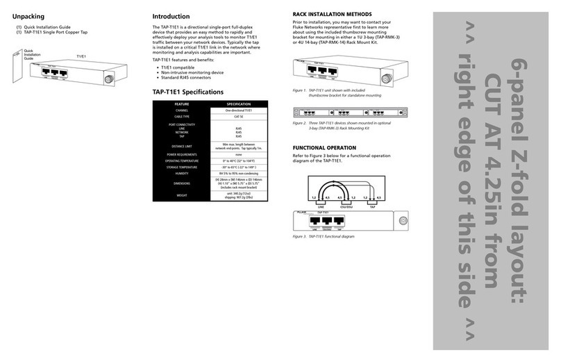
Fluke TAP-T1E1 User manual

Fluke

Fluke TAP-T1E1 User manual

Fluke STAP-BT-4X16 User manual

Fluke

Fluke STAP-BT-4X16 User manual

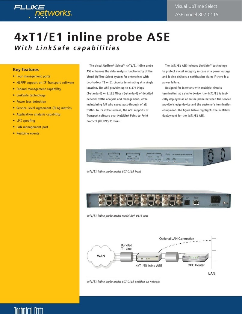
Fluke Visual UpTime Select 807-0115 User manual

Fluke

Fluke Visual UpTime Select 807-0115 User manual

Fluke SimpliFiber Pro User manual

Fluke

Fluke SimpliFiber Pro User manual

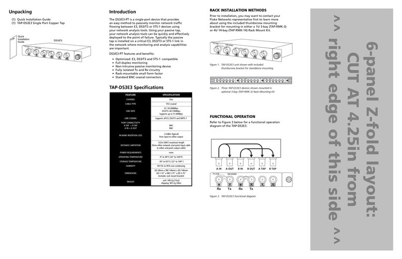
Fluke TAP-DS3E3 User manual

Fluke

Fluke TAP-DS3E3 User manual

Fluke OneTouch AT User manual

Fluke

Fluke OneTouch AT User manual

Popular Network Hardware manuals by other brands

Black Box 37688-R2 Specifications

Black Box

Black Box 37688-R2 Specifications

HIK VISION DS-7600NI-12 Series user manual

HIK VISION

HIK VISION DS-7600NI-12 Series user manual

Watchguard Firebox M290 quick start guide

Watchguard

Watchguard Firebox M290 quick start guide

HIK VISION 7604NI-K1B quick start guide

HIK VISION

HIK VISION 7604NI-K1B quick start guide

q-Tech QSW-2900 user manual

q-Tech

q-Tech QSW-2900 user manual

Zcom ZCN-1523H-5-16 Quick installation guide

Zcom

Zcom ZCN-1523H-5-16 Quick installation guide

Comelit 1468 Technical manual

Comelit

Comelit 1468 Technical manual

ZMODO ZMD-NV-SBN4 user manual

ZMODO

ZMODO ZMD-NV-SBN4 user manual

Ubiquiti UniFi WiFi BaseStation XG quick start guide

Ubiquiti

Ubiquiti UniFi WiFi BaseStation XG quick start guide

Newtec Shield96 quick start guide

Newtec

Newtec Shield96 quick start guide

Lanner ECA-4027 user manual

Lanner

Lanner ECA-4027 user manual

GW Security GW55 Series quick guide

GW Security

GW Security GW55 Series quick guide

Zinwell WB616 installation guide

Zinwell

Zinwell WB616 installation guide

Enterasys 802.11 Networking guide

Enterasys

Enterasys 802.11 Networking guide

TG-NET Cloud Box M-3 user manual

TG-NET

TG-NET Cloud Box M-3 user manual

LG LRN8240D Series Simple manual

LG

LG LRN8240D Series Simple manual

Valcom IP Solutions VIP-810 user guide

Valcom

Valcom IP Solutions VIP-810 user guide

Buffalo LS-WXL user manual

Buffalo

Buffalo LS-WXL user manual

manuals.online logo
manuals.online logoBrands
  • About & Mission
  • Contact us
  • Privacy Policy
  • Terms and Conditions

Copyright 2025 Manuals.Online. All Rights Reserved.