FOR-A USF-212PS User manual

USF-212S
Universal System Frame
USF-212PS
Power Supply Unit
2nd Edition
OPERATION
MANUAL

2
Precautions
Important Safety Warnings
[Power]
Caution
Operate unit only at the specified supply voltage.
Disconnect the power cord via the power plug only. Do not pull on the cable portion.
Stop
Do not place or drop heavy or sharp-edged objects on the power cord. A damaged
cord can cause fire or electrical shock hazards. Regularly check the power cord for
excessive wear or damage to avoid possible fire / electrical hazards.
Caution
Ensure the power cord is firmly plugged into the AC outlet.
[Grounding]
Caution
Ensure the unit is properly grounded at all times to prevent electrical shock.
Hazard
Do not ground the unit to gas lines, units, or fixtures of an explosive or dangerous
nature.
[Operation]
Hazard
Do not operate the unit under hazardous or potentially explosive atmospheric
conditions. Doing so could result in fire, explosion, or other hazardous results.
Hazard
Do not allow liquids, metal pieces, or other foreign materials to enter the unit. Doing so
could result in fire, other hazards, or a unit malfunction.
If a foreign material does enter the unit, turn the power off and immediately disconnect
the power cord. Remove the material and contact an authorized service representative
if damage has occurred.
[Transportation]
Hazard
Handle with care to avoid impact shock during transit, which may cause malfunction.
When you need to transport the unit, use the original or suitable alternative packing
material.

3
[Circuitry Access]
Do not remove covers, panels, casing, or access the circuitry with power applied to the
unit. Turn the power off and disconnect the power cord prior to removal. Internal
servicing / adjustment of unit should only be performed by qualified personnel.
Stop
Do not touch any parts / circuitry with a high heat factor.
Capacitors can retain enough electric charge to cause mild to serious shock, even after
the power has been disconnected. Capacitors associated with the power supply are
especially hazardous.
Hazard
Unit should not be operated or stored with cover, panels, and / or casing removed.
Operating the unit with circuitry exposed could result in electric shock / fire hazards or
a unit malfunction.
[Potential Hazards]
Caution
If abnormal odors or noises are noticed coming from the unit, immediately turn the
power off and disconnect the power cord to avoid potentially hazardous conditions. If
problems similar to the above occur, contact an authorized service representative
before attempting to operate the unit again.
[Rack Mount Brackets, Ground Terminal, and Rubber Feet]
Caution
To rack-mount or ground the unit, or to install rubber feet, do not use screws or
materials other than those supplied. Doing so may cause damage to the internal
circuits or components of the unit. If you remove the rubber feet that are attached to the
unit, do not reinsert the screws that secure the rubber feet.
[Consumables]
Caution
Consumable items that are used in the unit must be periodically replaced. For further
details on which parts are consumables and when they should be replaced, refer to the
specifications at the end of the Operation Manual. Since the service life of the
consumables varies greatly depending on the environment in which they are used,
such items should be replaced at an early date. For details on replacing consumable
items, contact your dealer.

4
Upon Receipt
USF-212S units and their accessories are fully inspected and adjusted prior to shipment. Operation can
be performed immediately upon completing all required connections and operational settings.
Check your received items against the packing lists below. Check to ensure no damage has occurred
during shipment. If damage has occurred, or items are missing, inform your supplier immediately.
USF-212S
ITEM
QTY
REMARKS
USF-212S
1
AC Cable
1 set
Includes AC Cord Retaining Clip
CD-ROM
1
Operation Manual (PDF)
Set up Guide
1
USF-212PS Option
ITEM
QTY
REMARKS
USF-212PS
1
Redundant Power Supply Unit
AC Cable
1 set
Includes AC Cord Retaining Clip

5
Table of Contents
1. Prior to Starting.....................................................................................................................................7
1-1. Overview .....................................................................................................................................7
1-2. Features......................................................................................................................................7
1-3. About This Manual......................................................................................................................7
2. Installing AC Cord Retaining Clip.........................................................................................................8
3. USF-212S Module List .........................................................................................................................9
4. Part Descriptions..................................................................................................................................9
4-1. Front Panel..................................................................................................................................9
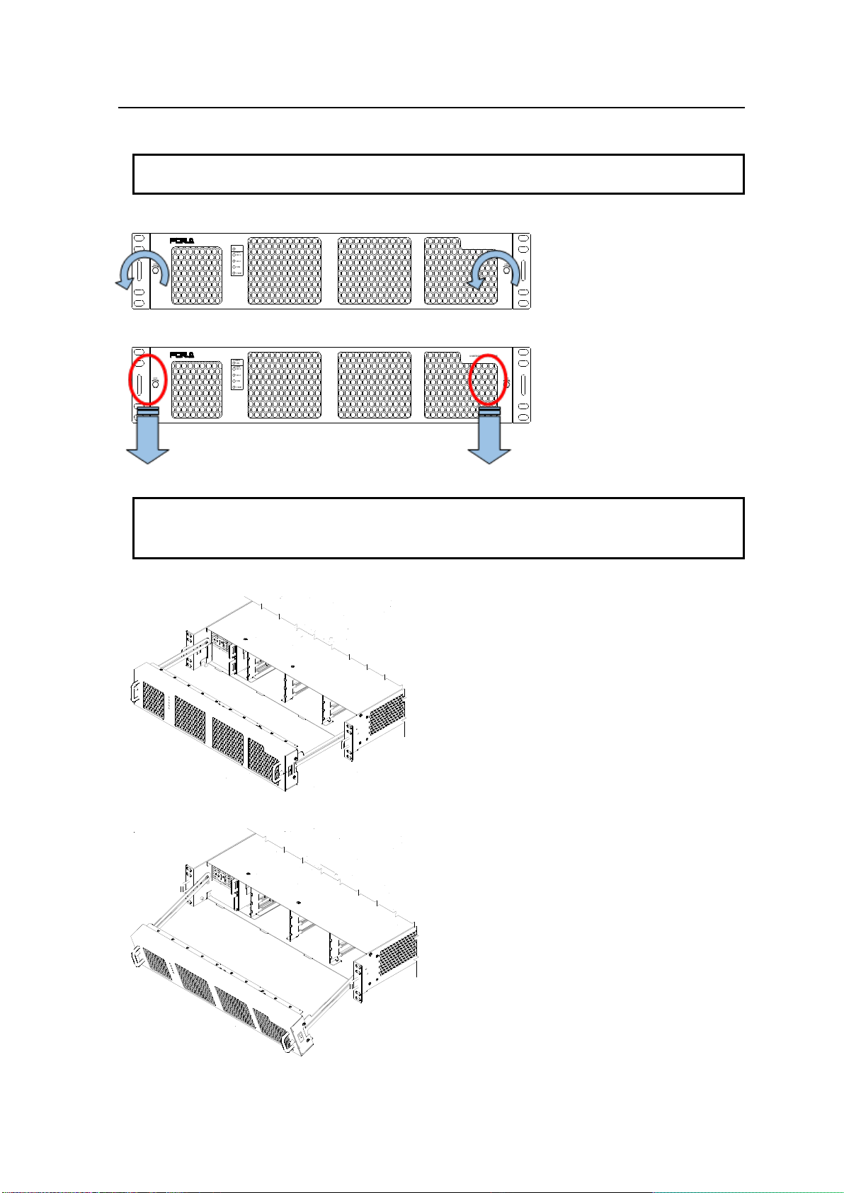
4-2. Opening the Front Panel...........................................................................................................10
4-3. Detaching the Front Panel ........................................................................................................11
4-4. Front Interior..............................................................................................................................12
4-5. Slot Number ..............................................................................................................................13
4-6. Power Supply............................................................................................................................13
4-7. Rear Panel ................................................................................................................................14
4-8. Fan............................................................................................................................................15
4-9. Internal SDI Bus........................................................................................................................15
4-10. ALARM Connector ..................................................................................................................16
4-10-1. Example of Alarm Connection.........................................................................................16
5. USF Module Installation .....................................................................................................................17
5-1. Installing of a USF Rear Module...............................................................................................17
5-2. Installing a USF Front Module ..................................................................................................18
6. Replacing a USF Module....................................................................................................................19
6-1. Removing the Front Module......................................................................................................19
6-2. Removing the Rear Module ......................................................................................................19
7. Installing or Removing a Power Supply Unit......................................................................................20
7-1. Installing a Power Supply Unit ..................................................................................................20
7-2. Removing a Power Supply Unit ................................................................................................21
8. Control Module ...................................................................................................................................22
8-1. Internal Control Module Settings...............................................................................................22
9. Control via Web GUI...........................................................................................................................23
9-1. Connecting USF-212S to a PC.................................................................................................23
9-1-1. Connecting LAN 1 and LAN 2 Ports..................................................................................23
9-1-2. LAN A Port.........................................................................................................................24
9-2. PC System Requirements.........................................................................................................24
10. USF-212S Web GUI.........................................................................................................................25
10-1. Status Tab...............................................................................................................................25
10-2. Alarm Tab................................................................................................................................27
10-3. Network Tab............................................................................................................................28
10-4. SNMP Tab...............................................................................................................................30
10-5. Utility Tab ................................................................................................................................32
11. About SNMP.....................................................................................................................................34
12. Specifications and Dimensions ........................................................................................................36
12-1. Specifications..........................................................................................................................36
12-1-1. USF-212S........................................................................................................................36
12-1-2. USF-212PS......................................................................................................................36
12-2. External Dimensions...............................................................................................................37
12-2-1. USF-212S........................................................................................................................37
12-2-2. USF-212PS......................................................................................................................37

6

7
1. Prior to Starting
1-1. Overview
The USF-212S is a low cost and space saving Universal System Frame that can be freely
configured. Up to 12 modules can be installed into one USF frame.
Dual, redundant power supplies can be configured by adding an optional USF-212PS power unit,
improving operation safety.
An internal switching hub and router allows high speed network communications and flexible
network systems.
1-2. Features
Up to 12 USF modules (boards) can be installed to match your system requirements.
Installing a USF-212PS enables a redundant (dual power supply) configuration.
All modules can be replaced from the front. Power supply units and front USF module units
both support hot-swapping.
Alarm sensors (Fan Stop/ Power Unit Voltage Error/ Temperature Error) and status indicators
(Power/ Fan/ Temperature) are shown on front LEDs.
Alarm data able to output from rear connectors.
Two genlock inputs (BB or Tri-level sync) with loop-through.
(Input reference signal able to be supplied to all frame modules installed in the unit.)
EIA Standard 2RU size.
Monitoring with SNMP available.
High speed connection of each module via internal switching hub.
USF modules can be monitored and controlled via PC web browser.
1-3. About This Manual
This manual is intended to help the user easily operate this product and make full use of its
functions during operation. Before connecting or operating your unit, read this operation manual
thoroughly to ensure you understand the product. Afterwards, store this manual in a safe place for
future reference.

8
2. Installing AC Cord Retaining Clip
Secure the AC cord with the supplied ladder strap/retaining clip assembly to prevent accidental
disconnection from the USF-212S.
Installing the clip
1) Wrap the retaining clip around the AC cord (with the anchor of the ladder strap toward the unit).
2) Insert the anchor into the hole next to the AC IN socket.
3) Lightly fasten the clip around the AC cord.
4) Plug in the power cord.
5) Slide the clip on the ladder strap toward the plug.
6) Fasten the clip tightly.
7) Gently pull on the AC cord to ensure it is secured.
Unplugging the AC Cord
1) Push the tab on the retaining clip to unfasten the clip.
2) Push the tab on the ladder strap up and slide the clip back.
3) Unplug the AC cord.
1)
2)
2)
4)
3)
5)
6)

9
3. USF-212S Module List
Module
Comments
USF-1040VEA
Optional USF-VEAIF is required to set via Web GUI.
USF-1100VEA
Optional USF-VEAIF is required to set via Web GUI.
USF-1053DDA
USF-108ADA
Optional USF-ADAIF is required to set via Web GUI.
USF-1043FS
USF-1043DCC
Remote control requires FA-10DCCRU option.
USF-1013MUX
USF-1013DEMUX
4. Part Descriptions
4-1. Front Panel
TEMP
FAN
DC2
DC1
ALARM
ON
POWER
USF-212
UNIVERSAL SYSTEM FRAME
LOCK LOCK
No.
Name
Description
(1)
POWER ON
This LED lights green when DC power is supplied normally
DC 1
This LED lights red when a voltage error occurs in power module 1.
DC 2
This LED lights red when a voltage error occurs in power module 2.
FAN
This LED lights red when at least one fan has stopped.
TEMP
This LED lights red when a temperature error occurs in the power
supply module(s). Lower the environmental temperature to continue
operation.
(2)
FAN1
Cooling fans. Operation status can be monitored by Web GUI Status
Tab. Refer to Sec.10-1. “Status Tab.”
(3)
FAN2
(4)
FAN3
* DC 1 and DC 2 become functional when a USF-212PS power supply option is installed.
(1)
(4)
(3)
(2)

10
4-2. Opening the Front Panel
IMPORTANT
The front panel may be difficult to open if the USF frame is placed on a desk, and may be
damaged if it is forced to open. Perform the following steps after setting the frame in a rack
1. Loosen the two thumbscrews on the front panel by turning them counterclockwise.
TEMP
FAN
DC2
DC1
ALARM
ON
POWER
USF-212
UNIVERSALSYSTEM FRAME
LOCK LOCK
2. Pull out the front panel using the pull handles. The fan stops while the front panel is open.
TEMP
FAN
DC2
DC1
ALARM
ON
POWER
USF-212
UNIVERSALSYSTEM FRAME
LOCK LOCK
IMPORTANT
An OPEN alarm sounds intermittently, every 30 seconds, when the front panel is opened.
After 5 minutes, the alarm will sound continuously until the front panel is closed.
In case the power is on, complete the procedure in a short period of time
3. Pull out the front panel as shown in the figure below.
4. The front panel rails can be tilted down.

11
4-3. Detaching the Front Panel
1. Fully draw out the front panel.
2. The front panel can be detached by gently pushing both rails inward.
NOTE
Handle the front panel carefully so as not to bend the rails.
IMPORTANT
After the front panel is installed, the ALARM LED on the front panel will light in the following
order.
DC1 → DC2 → FAN → TEMP
The ALARM LEDs not lighting in the above order indicates the front panel have not been
installed properly. Re-install the front panel.

12
4-4. Front Interior
The slot configuration as shown below is revealed when the front panel is removed.
No.
Slot Type
Description
(1)
Power Supply 1 Slot
Dedicated power unit installed in this slot as standard.
Power is supplied when the power supply switch is turned on.
(2)
Power Supply 2 Slot
Slot for redundant power supply USF-212PS. Redundant
operation available when optional USF-212PS is installed.
A blank panel will otherwise cover the slot.
(3)
Control module Slot
Slot for network module.
SNMP Monitoring and GPI alarm output from the rear terminal
LAN1/LAN2/LAN A are available. Allows control over the
respective modules.
Allows to supply GENLOCK1/2 to respective slots.
(4)
Expansion slot
Not used.
(5)
USF Module Slots
Dedicated USF module slots. (Front USF modules)
For details on module operation, refer to the respective operation
manuals.
Redundant Power Supply System
Two power supply units can be mounted in the USF-212S. By mounting two power supply
units and turning both units on, operation can continue without the DC power supply shutting
down if either power unit fails.
The dedicated and optional USF-212PS power supply units are the same configuration, and
can be exchanged. Refer to Sec. 7. "Installing or Removing a Redundant Power Supply Unit”
for installation details.
(1)
(2)
(3)
(4)
(5)

13
4-5. Slot Number
Front internal view.
Rear view.
4-6. Power Supply
Stand by power is activated in the USF-212S power supply unit when the AC cable is inserted.
When the front switch of the USF-212PS Power Supply unit is turned off, the DC supply to
USF-212S is disconnected. Redundant operation is available by installing an optional USF-212PS
power supply unit.
* When an optional USF-212PS is not installed, a blank panel is used to cover the blank power
supply unit 2 (PS2) slot.
NOTE
Turn on the power supply switch on the front panel after connecting the power supply cable.
Turn on both the dedicated and redundant power supply units. If only one power supply unit is
turned on, redundant power will not be enabled if power fails in a power supply unit.
On/Off switch of Power
Supply Unit 1
Slot for USF-212PS optional
power supply unit

14
4-7. Rear Panel
VIDEO IN T HRU
1 2 1
3G/HD/SDSDI IN
USF-1043FS
USF-1040VEA
1 2
2
3G/HD/SD SDI OUT
VIDEOOUT 3
3
4
4
IN OUT 1/2 3/4 5/6 7/8
-LTC
DIGITAL AUDIOI N
1/2 3/4 5/6 7/8
-LTC
DIGIT AL AUDIOOUT
IN OUT
3G/HD/SDSDI
3G/HD/SDSDI
USF-1013MUX
USF-1013DEMUX
1 2
3G/HD/SD SDI IN
USF-1043DCC
1 2
3G/HD/SD SDI OUT 3 4
5 6 7
VIDEOOUT 1
VIDEO IN T HRU
USF-1100VEA
8 9
2 3
10
4LAN 1
LAN 2
GENLOCK 1
GENLOCK 2
LAN A
SER. NO.
AC 100-240V 50 /60Hz IN 1
AC 100-240V 50 /60Hz IN 2
ALARM USF-212
ANALOGAUDIO
SDI IN 1 2 3 4 5
SDI OUT
USF-108ADA
USF-1053DDA
No.
Connector
Descriptions
(1)
AC Inlet for
power supply 1
Supplies AC100 to 240V power using the provided power supply
cable.
(2)
AC Inlet for
power supply 2
When an optional USF-212PS is installed, supplies AC100 to 240V
power using the provided power supply cable.
(3)
Ground terminal
Grounds the power supply for safety.
(4)
GENLOCK 1
GENLOCK 2
Inputs genlock signals: Black Burst (BB) or tri-level sync.
The lower connector is for a loop-through connection. Terminate
with 75Ω. if unused.
*BB or tri-level sync signal input to GENLOCK1 or 2 should meet
respective modules signal format specifications.
(5)
LAN 1
LAN 2
USF-212S and each module installed in Slot 1 to 12 are accessible
via the USF-212S internal switching hub. Refer to Sec. 9-1-1.
"Connecting LAN 1 and LAN 2 Ports” for details.
(6)
LAN A
USF-212S and each module installed in Slot 1 to 12 are accessible
via the USF-212S internal router. Refer to Sec. 9-1-2 "LAN A Port”
for details.
(7)
ALARM
Open collector output allows the respective output of alarms.
Refer to Sec. 4-10. "ALARM Connector” for details.
Refer to Sec. 10-2. "Alarm Tab” for details on alarm terminal settings
(8)
AC Cord
Retainer
Installation
An anchor bolt is placed to install the AC cord retainer. Refer to
Sec. 2 "Installing AC Cord Retaining Clip” for installation.
(5)
(6)
(1)
(2)
(7)
(4)
(3)
(8)

15
4-8. Fan
Fan unit prevents overheating from internal heat generation, pulling air through the front panel and
out the rear and right side panels. Do not block the fan vents.
(Rear Panel)
(Front Panel)
Air Flow Diagram
4-9. Internal SDI Bus
The USF-212S frame provides 4-slot groupings internal SDI bus which allows SDI signals to be
transferred bi-directionally. The signal application differs for each module. Refer to the operation
manual of each module for details.
♦Internal bus connections, Slots 1 to 4 ♦Internal bus connections, Slots 5 to 8
♦Internal bus connections, Slots 9 to 12
Slot 1
Slot 3
Slot 4
Slot 2
Slot 5
Slot 7
Slot 8
Slot 6
Slot 9
Slot 11
Slot 12
Slot 10

16
4-10. ALARM Connector
9-pin D-sub female
ALARM Connector Assignment Table (9-pin D-sub female)
No.
Signal
Signal Details
1
ALARM 1
ALARM 1 to 6 functions assigned through Web GUI setting page.
Refer to Sec. 10-2. "Alarm Tab”
2
ALARM 2
3
ALARM 3
4
ALARM 4
5
ALARM 5
6
ALARM 6
7
GND
GND
8
GND
GND
9
GND
GND
* Open collector alarm output (ALARM 1 to 6)
Maximum current limit: 24VDC / 50mA
4-10-1. Example of Alarm Connection
Example of ALARM1/ALARM2 (Open-Collector Output) Circuit
Power
Supply
50mA Max
Set the resistance so that the output
pin current stays within 50 mA.
R
External power supply
Max. +24VDC.
GND
ALARM 1
ALARM 2
USF-212S Side
Matching connector
9-pin D-sub male
*Using inch screws

17
5. USF Module Installation
USF Modules can be installed into any free slot. If multiple free slots exist, do not install modules
side-by-side but leave slots open to prevent overheating and facilitate signal connection from the rear
panel.
NOTE
USF Modules come as front and rear sets. Be sure to install set modules into the same (front and
rear) slot locations.
Always install the rear module first, then the front module.
Install blank panels over free slots to prevent foreign material from entering and overheating the
chassis.
IMPORTANT
Beware of the occurrence of electrical breakdown in USF Modules.
Wear an antistatic wrist strap or equivalent material to equalize the electrical potential of the
USF-212S unit and the worker’s body. Do not touch the PCB wiring or parts legs directly with your
fingers while working.
Each USF Module can be installed and uninstalled while the power is on in case of emergency.
Shut down the power for non-emergency work.
When installing/uninstalling the front module while the power is on, the front panel will be open
state. The fan will stop during the procedure, so it is essential to complete the installation within a
short period and to close the front panel immediately.
Be sure to shut down the power to install and uninstall a control module.
The procedure for installing the USF module in SLOT1 is described below as an example.
5-1. Installing of a USF Rear Module
1. Open the front panel and shut down the USF-212 power supply.
Refer to Sec. 4-2. "Opening the Front Panel”.
2. Slot 1 is the top slot in the left module block in the rear panel. Remove the blank panel by
detaching the two screws on both ends. Keep the blank panel and screws in a safe place after
removal.
3. Insert the rear module into the slot and fasten both screws.
AC100
-
240V
50/60Hz
IN
S
E
R
.
N
O
.
Loosen
screw
Loosen
screw
3G/HD/SD SDI IN
USF-1043FS
1 2 1 2 3 4
3G/HD/SD SDI OUT
Fasten
screw
Fasten
screw.

18
5-2. Installing a USF Front Module
IMPORTANT
Make sure to install the front module after installing the rear module.
1. Slot 1 is the top slot in the right block of the front panel. Refer to Sec. 4-5. "Slot Number”
2. Set the front module on the guide rail and carefully insert the front module slowly.
PCB Guide Rail Locations
3. Push the handle until the front module clicks into the connectors.
IMPORTANT
Inserting the module by pressing on other than the handle may damage the module.
When a front module is installed with power on, maximum 1 minute is required until the
module is detected and identified on the web.
PCB Guide Rail
PCB Guide Rail
PCB Guide Rail
PCB Guide Rail

19
6. Replacing a USF Module
Follow the procedure described below to remove and replace a defective USF Module. Since no
electrical components are mounted on most USF rear modules, it is possible to recover proper operation
by replacing front modules.
NOTE
When both front and rear module are to be replaced, make sure to replace the rear module after
pulling out the front module.
IMPORTANT
Beware of the occurrence of electrical breakdown in USF Modules.
Wear an antistatic wrist strap or equivalent material to equalize the electrical potential of the
USF-212S unit and the worker’s body. Do not touch the PCB wiring or parts legs directly with your
fingers while working.
Each USF Module can be installed and uninstalled while the power is on in case of emergency.
Shut down the power for non-emergency work.
When installing/uninstalling the front module while the power is on, the front panel will be open
state. The fan will stop during the procedure, so it is essential to complete the installation within a
short period and to close the front panel immediately.
Be sure to shut down the power to install and uninstall a control module.
The procedure for replacing a module in Slot 4 is described below as an example.
6-1. Removing the Front Module
1. Open the front panel and shut down the USF-212S power supply.
Refer to Sec. 4-2. "Opening the Front Panel.”
2. Slot 4 is the bottom slot in the right block of the front panel. Refer to Sec. 4-5. "Slot Number.”
3. Slide the module out using the grab handle.
6-2. Removing the Rear Module
IMPORTANT
Always remove the front module first, then the rear module without exception.
1. Slot 4 is the bottom slot in the left block of the rear panel. Refer to Sec. 4-5. "Slot Number”
2. Loosen the screws on both ends. Secure the rear module while loosening the screws in order
not to drop the module.
VIDEO IN T HRU
1 2 1
3G/HD/SDSDI IN
USF-1043FS
USF-1040VEA
1 2
2
3G/HD/SD SDI OUT
VIDEOOUT 3
3
4
4
IN OUT 1/2 3/4 5/6 7/8
-LTC
DIGITAL AUDIOIN
1/2 3/4 5/6 7/8
-LTC
DIGITAL AUDIOOUT
IN OUT
3G/HD/SDSDI
3G/HD/SDSDI
USF-1013MUX
USF-1013DEMUX
1 2
3G/HD/SD SDI IN
USF-1043DCC
1 2
3G/HD/SD SDI OUT 3 4
5 6 7
VIDEOOUT 1
VIDEO IN T HRU
USF-1100VEA
8 9
2 3
10
4LAN 1
LAN 2
GENLOCK 1
GENLOCK 2
LAN A
SER. NO.
AC100-240V 5 0/60Hz IN 1
AC100-240V 5 0/60Hz IN 2
ALARM USF-212
ANALOGAUDIO
SDI IN 1 2 3 4 5
SDI OUT
USF-108ADA
USF-1053DDA
Screw
Screw

20
7. Installing or Removing a Power Supply Unit
The procedure for installing a USF-212PS Optional Redundant Power Supply Unit into a USF frame is
described as follows. Power supply unit replacement can be performed in the same manner.
IMPORTANT
To avoid electric shock, make sure to ground the grounding terminal before operation or pull out the
AC cable from the outlet.
A USF-212PS redundant power supply unit can be installed while the power is on, although the (main)
USF-212S power supply should normally be turned off when doing so. To install or remove a power
supply unit while the power is on, open the front panel. The cooling fan of the unit is turned off when
the front panel is open, so the installation should be completed in a short time to avoid overheating.
Close the front panel immediately after the operation is completed.
7-1. Installing a Power Supply Unit
The procedure for installing a USF-212PS unit into the PS2 Slot is explained as an example.
1. Open the front panel. Refer to Sec. 4-2.”Opening the Front Panel”
2. Turn counterclockwise to remove the screw of the power supply mounting bracket.
3. Remove the blank panel when a power unit blank panel is installed.
4. Insert the power supply unit USF-212PS slowly into the power supply slot from the front.
5 Fix the power supply unit with the fixing bracket removed in step 2, then tighten the screw.
6. Connect the power supply cable from the rear.
7. Turn on the USF-212PS front switch.
8. Close the front panel.
IMPORTANT
After connecting the power supply cable, turn the front switch on. Turn on both the dedicated
power supply and redundant power supply. If both power supplies are not turned on, redundant
operation will not work in the case of a power supply unit failure.
Screw of Fixing
Bracket
Table of contents
Other FOR-A Power Supply manuals