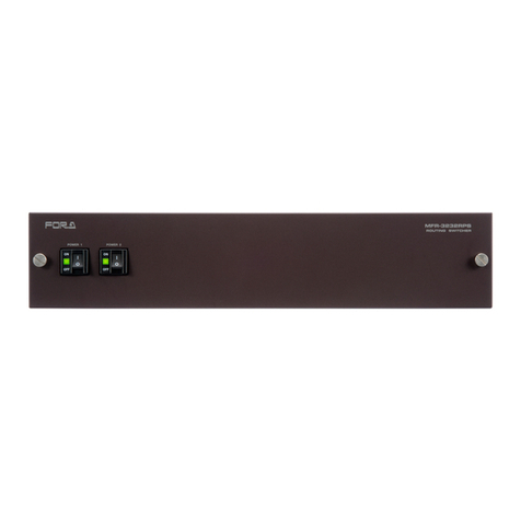
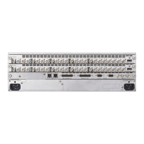
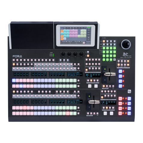
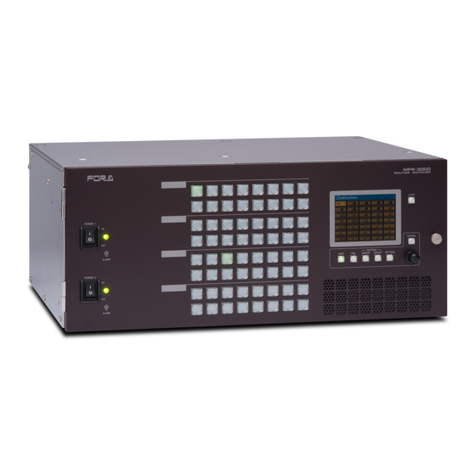
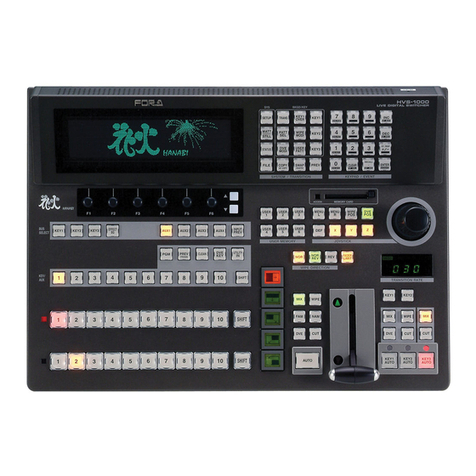
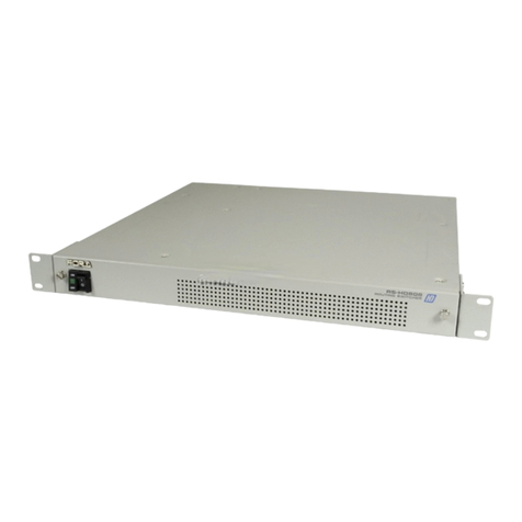
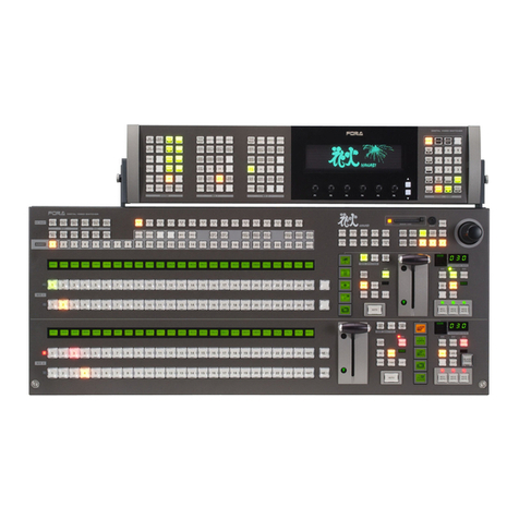
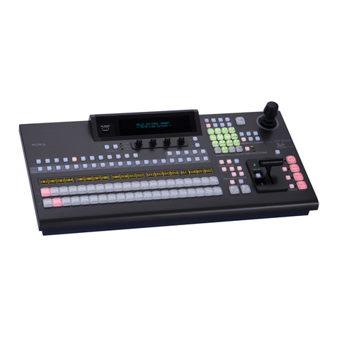
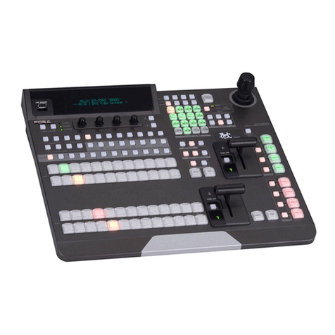
FOR-A VPS-700 MU User manual

Released: 05/01/2007
FOR-A Co., Ltd.
VPS-700OU
Important Note On USB Memory
Do not power on VPS-700OU with a USB flash memory inserted in the USB port of
VPS-700OU.
If VPS-700OU is powered on with a USB memory inserted by mistake, VPS-700OU cannot
start up properly, displaying such messages as "Now Initializing..." on the menu display.
In this case, make sure there is no memory access (access lamp is not flashing.) and
remove the USB memory from the USB port. And then power off, then on VPS-700OU.


VPS-700 MU
Video Production System
VPS-700RPS MU
Video Production System
VPS-700OU
Operation Unit
5th Edition
OPERATION
MANUAL

Edition Revision History
Edit. Rev. Date Description Section
1 - 2005-10-25
1 1 2005-11-04 Added Shutdown procedure.
1 2 2005-12-28 Changed Startup screen.
Added VPS-70DPUIF.
Changed output signal description.
Changed Memory management for OU and USB.
Changed Event operation.
Added Sequence Edit.
2 - 2006-07-18 Added analog expansion card setup procedure.
Corrects signal names, pattern pictures, still store and
pre-combiner description.
2 1 2007-01-17 Changed MU/OU control cable.
Corrects USB port specification.
Corrects Joystick Default procedure.
Added default procedure for WIPE and DVE modify
menu.
Corrected and Added pre-combiner operation example.
Corrected and Added event operations.
Corrected other factual errors.
2-3-2
2-3, 16-1-2
5-3-2
9-1, 10-1
12
13
3 - 2007-05-31 Added Color Control.
Added Defocus (Warp option).
Added Strobe.
Added Event Target.
Added Remap Link.
Corrected other factual errors.
10-5-2
10-5-3
10-6-10
13-2
12-3
4 - 2008-3-18 Added VPS-70FR
Changed file management description
Changed flash recorder (option) description
Changed OU clearing and backing up description
Corrected other factual errors.
13
4-5
13
17-2
4 1 2008-5-31 Changed VPS-700RPS rear panel illustration
Changed the detailed drawing of VPS-700RPS 2-2
18-2-2
5 - 2010-2-1 Added information about setting graphic Wipes with Flash
Recorder (option).
Changed the title of section 17-2
Added Odd/Even/Any selection for button performances
Changed the title, structure, and contents of section 5, 7
and 8
Corrected other factual errors
14-6
17-2
18-4-4
5, 7, 8

Precautions
Important Safety Warnings
[Power]
Operate unit only on the specified supply voltage.
Disconnect power cord by connector only. Do not pull on cable portion.
Do not place or drop heavy or sharp-edged objects on power cord. A damaged cord
can cause fire or electrical shock hazards. Regularly check power cord for
excessive wear or damage to avoid possible fire / electrical hazards.
[Grounding]
Ensure unit is properly grounded at all times to prevent electrical shock hazard.
Do not ground the unit to gas lines, units, or fixtures of an explosive or dangerous
nature.
Ensure power cord is firmly plugged into AC outlet.
[Operation]
Do not operate unit in hazardous or potentially explosive atmospheres. Doing so
could result in fire, explosion, or other dangerous results.
Do not allow liquids, metal pieces, or other foreign materials to enter the unit. Doing
so could result in fire, other hazards, or unit malfunction.
If foreign material does enter the unit, turn power off and disconnect power cord
immediately. Remove material and contact authorized service representative if
damage has occurred.
[Transportation]
Handle with care to avoid shocks in transit. Shocks may cause malfunction. When
you need to transport the unit, use the original packing materials or alternate
adequate packing.
Stop
Caution
Hazard
Hazard
Caution
Hazard
Caution
Caution

[Circuitry Access]
Do not remove covers, panels, casing, or access circuitry with power applied to the
unit! Turn power off and disconnect power cord prior to removal. Internal servicing /
adjustment of unit should only be performed by qualified personnel.
Do not touch any parts / circuitry with a high heat factor.
Capacitors can retain enough electric charge to cause mild to serious shock, even
after power is disconnected. Capacitors associated with the power supply are
especially hazardous. Avoid contact with any capacitors.
Unit should not be operated or stored with cover, panels, and / or casing removed.
Operating unit with circuitry exposed could result in electric shock / fire hazards or
unit malfunction.
[Potential Hazards]
If abnormal smells or noises are noticed coming from the unit, turn power off
immediately and disconnect power cord to avoid potentially hazardous conditions. If
problems similar to above occur, contact authorized service representative before
attempting to again operate unit.
[Rack Mount Brackets, Ground Terminal, and Rubber Feet]
To rack mount or ground the unit, or to install rubber feet, do not use screws or
materials other than those supplied. Otherwise, it may cause damage to the internal
circuits or components of the unit. If you remove the rubber feet attached on the unit,
do not reinsert the screws securing the rubber feet.
[Consumables]
The consumables used in unit must be replaced periodically. For further details on
which parts are consumables and when they should be replaced, refer to the
specifications at the end of the Operation Manual. Since the service life of the
consumables varies greatly depending on the environment in which they are used,
they should be replaced at an early date. For details on replacing the consumables,
contact your dealer.
Caution
Hazard
Stop
Caution
Caution

Upon Receipt
Unpacking
The VPS-700 and any of its options you may have purchased are fully inspected and adjusted
prior to shipment and can be operated immediately upon completing all required connections
and operational settings. Check your received items against the packing lists below.
MU Box Contents
ITEM QTY REMARKS
VPS-700 MU or
VPS-700RPS MU 1
VPS-700 main processing unit (Single Power Supply model)
VPS-700RPS main processing unit (Redundant power supply
model)
* Note that the VPS-700MU units cannot be upgraded to
VRP-700RPS MU. Be careful to select the right model.
AC Cord 1-2 For AC power connection
One for VPS-700 MU and two for VPS-700RPS MU
Rack Mount
Brackets 1 pr. Rack mounting to EIA standard type
OU Box Contents
VPS-700OU 1 VPS-700 operation unit
Control Cable 1 For connection between MU and OU, 10m
(RJ-45, 10Base-T/100Base-TX, Category 5, Cross-over cable)
AC Cord 1 For AC power connection
Operation Manual 1
Internal Options
VPS-70SDI 1-2 For addition of 4 SD-SDI inputs (max 2 cards)
VPS-70SDO 1-2 For addition of 4 SD-SDI outputs (max 2 cards)
VPS-70AI 1-4 For addition of 2 analog inputs (max 4 cards)
VPS-70AO 1-2 For addition of 2 analog outputs (max 2 cards)
VPS-70DS 1-2 Pre-combiner card with16 channels of DVE (max 2 cards)
VPS-70FR 1-2 Flash Recorder (max 2 cards)
VPS-70CK 1 Chromakey module (hardware dongle)
VPS-70Warp 1 Advanced 3D DVE Warp module (hardware dongle)
VPS-70DPUIF 1 Display Interface Module (hardware dongle)
Refer to each card installation manual for how to install option card. After installation, refer to sections 4-6.
"Input Expansion Option" and 4-7. "Output Expansion Option" to setup analog inputs and / or outputs.
External Options and Devices
VPS-70DPU 1 Touch Panel Display Unit
VPS-70DPUA 1 Touch Panel Display Unit
HVS-AUX8/16/32 1 Auxiliary control unit
Control cable 1 For VPS-700 and HVS-AUX16/32 connection (PC-3168-1, 10m)
Control cable 1 For VPS-700 and Virtual device (RS-422A cable)
Refer to sections 3-3 and 4-8 for HVS-AUX8/16/32 connection and setup. See the HVS-AUX8/16/32
operation manual for how to control the auxiliary units.

Check
Check to ensure no damage has occurred during shipment. If damage has occurred, or items
are missing, inform your supplier immediately.
Rack Mounting
The VPS-700 can be mounted to EIA standard rack units. When rack mounting a unit, use the
accessory rack mount brackets (rack ears).

Table of Contents
1. Prior to Starting...........................................................................................................................1
1-1. Welcome.............................................................................................................................1
1-2. VPS-700 Overview..............................................................................................................1
1-3. About This Manual..............................................................................................................2
1-4. Basic Switcher Operations..................................................................................................3
1-4-1. Background Transitions ..............................................................................................3
1-4-2. Key Transitions ...........................................................................................................4
1-4-3. DVE Pictures ..............................................................................................................5
1-4-4. Sequence Operation...................................................................................................6
2. Panel Description........................................................................................................................7
2-1. VPS-700 MU (Single PS Model).........................................................................................7
2-2. VPS-700RPS MU (Redundant PS Model)..........................................................................8
2-3. Operation Unit.....................................................................................................................9
2-3-1. Control Panel..............................................................................................................9
2-3-2. Rear Panel................................................................................................................10
2-4. Interfaces..........................................................................................................................11
2-5. MU Rear Panel Cards.......................................................................................................14
3. Connection and Setup ..............................................................................................................15
3-1. Basic Connection..............................................................................................................15
3-2. Optional Configuration......................................................................................................16
3-3. Connection for Aux Output Control (Option) .....................................................................17
4. Setup ........................................................................................................................................18
4-1. Power ON.........................................................................................................................18
4-2. Selecting System Signal Format.......................................................................................19
4-3. Power OFF .......................................................................................................................20
4-4. Quick Reference for Menu Setting....................................................................................21
4-5. File Management..............................................................................................................22
4-6. Input Expansion Option.....................................................................................................24
4-6-1. Available Combinations of Card Installations............................................................24
4-6-2. Adjustments on CPU Card........................................................................................25
4-6-3. Settings for Optional Inputs.......................................................................................26
4-7. Output Expansion Option..................................................................................................27
4-7-1. Available combinations of card installations..............................................................27
4-7-2. Settings for Optional Analog Outputs........................................................................28
4-8. Connection Settings for Aux Output Control .....................................................................29
4-9. Easy Virtual Connection Setting........................................................................................30
5. Menu Description......................................................................................................................31

5-1. Menu Overview ................................................................................................................31
5-2. Menu Display....................................................................................................................33
5-3. How to Access Menus......................................................................................................34
5-3-1. How to Use Menus................................................................................................... 36
5-3-2. Keypad Input............................................................................................................37
5-3-3. Joystick Input............................................................................................................38
5-4. Returning to Default .........................................................................................................39
5-4-1. Using Menu Controls................................................................................................39
5-4-2. Using Buttons in Joystick Section.............................................................................39
6. Touch Panel Operations (Option).............................................................................................40
7. Signal Setting Workflow............................................................................................................ 41
7-1. Input Signal ......................................................................................................................41
7-1-1. Signal Name.............................................................................................................41
7-1-2. Changing Signal Name ............................................................................................41
7-1-3. Selecting Signals for Background............................................................................. 43
7-1-4. Assigning Signals to M/E Bus...................................................................................44
7-1-5. Input Signal and Frame Synchronizer Modes .......................................................... 45
7-1-6. Input Signal Adjustments (Proc Amp).......................................................................46
7-1-7. Selecting Signals for Keys and DSKs.......................................................................46
7-2. Output Signals..................................................................................................................47
7-2-1. Assigning Signals to Auxiliary Outputs .....................................................................47
7-2-2. Selecting Signals for PREV and CLEAN Outputs.....................................................48
7-2-3. Selecting Preview Output.........................................................................................49
8. Transition Operations ...............................................................................................................50
8-1. About Transitions..............................................................................................................50
8-1-1. Transition Rate.........................................................................................................51
8-2. Background Transitions....................................................................................................52
8-2-1. Cut............................................................................................................................52
8-2-2. Mix............................................................................................................................53
8-2-3. WIPE and DVE......................................................................................................... 54
8-2-4. Fader Limit ...............................................................................................................55
8-3. Key and DSK Transitions .................................................................................................56
8-3-1. DSK Transitions and Changing Priority Orders ........................................................ 56
8-3-2. Key Cut Transitions..................................................................................................57
8-3-3. Mix Transitions for Keys...........................................................................................57
8-3-4. Wipe Transitions for Keys......................................................................................... 58
8-3-5. DVE Transitions for Keys .........................................................................................59
8-3-6. Priority Order Change of Keys.................................................................................. 59
8-4. BLACK Transitions...........................................................................................................60
9. Keyer / DSK Setup...................................................................................................................61
9-1. Keyer /DSK Setup Menu...................................................................................................61
9-2. Mask.................................................................................................................................63
9-3. Edge and Shadow.............................................................................................................64
9-4. Making and Adjusting Chromakeys (Option).....................................................................66
9-4-1. Auto Key ...................................................................................................................66
9-4-2. Adjusting Chromakey................................................................................................67
9-5. Assigning DVEs to Keyers................................................................................................69
9-5-1. About DVE Channels................................................................................................69
9-5-2. Opening DVE Menus and Assigning DVE.................................................................69
10. Wipe Modify............................................................................................................................70
10-1. Returning Wipe Modify Setting to Default.......................................................................71
10-2. Wipe Modify Example.....................................................................................................71
11. DVE Modify.............................................................................................................................72
11-1. Returning DVE Modify Setting to Default ........................................................................72
11-2. DVE Modify Example......................................................................................................73
11-3. Basic...............................................................................................................................75
11-3-1. Position and Rotation..............................................................................................75
11-3-2. Aspect .....................................................................................................................76
11-3-3. Setup.......................................................................................................................76
11-4. Border .............................................................................................................................77
11-5. Sub Effect........................................................................................................................79
11-5-1. Trail .........................................................................................................................79
11-5-2. Chroma Control.......................................................................................................80
11-5-3. Strobe......................................................................................................................80
11-6. Warp (Option)..................................................................................................................81
11-6-1. Ripple......................................................................................................................81
11-6-2. Swirl ........................................................................................................................82
11-6-3. Mosaic.....................................................................................................................82
11-6-4. Slats........................................................................................................................82
11-6-5. Lens ........................................................................................................................83
11-6-6. Page Turn................................................................................................................84
11-6-7. Page Peel................................................................................................................85
11-6-8. Splits .......................................................................................................................85
11-6-9. Mirror.......................................................................................................................86
11-6-10. Defocus.................................................................................................................86
11-7. Light (Option) ..................................................................................................................87
11-7-1. Type ........................................................................................................................87
11-7-2. Light 1-2..................................................................................................................87
12. Internally Generated Signals...................................................................................................88
12-1. Bus Mattes......................................................................................................................88
12-2. Still Store.........................................................................................................................88

12-2-1. Downloading Still Images from USB.......................................................................89
12-2-2. Capturing Program Out and Saving Still................................................................. 90
12-2-3. Assigning Stills to Video Sources ...........................................................................90
12-2-4. Exporting Stills to USB Flash Memory Drive ..........................................................91
12-2-5. Deleting Still File.....................................................................................................91
12-2-6. 32-bit TGA Images .................................................................................................92
13. Pre-combiner (Option)............................................................................................................93
13-1. Setting Up Pre-combined Images................................................................................... 93
13-2. Editing Pre-combined Images ........................................................................................95
13-3. Merging Input Mapping................................................................................................... 96
13-4. Pre-combined Image Setting Example...........................................................................96
13-4-1. Setting Up Image A ................................................................................................ 97
13-4-2. Setting Up Image B................................................................................................ 99
13-4-3. Making Transition.................................................................................................100
14. Flash Recorder (Option)....................................................................................................... 101
14-1. Managing Frame Memory ............................................................................................ 101
14-2. Initializing .....................................................................................................................102
14-3. Recording in Tracks......................................................................................................103
14-4. Editing Clips ................................................................................................................. 104
14-5. Clip Playback................................................................................................................105
14-6. Deleting Clips...............................................................................................................107
15. Event Memory...................................................................................................................... 109
15-1. Storing Events..............................................................................................................109
15-2. Recalling Events............................................................................................................110
15-3. Clearing Events.............................................................................................................112
15-4. Backing up Events to OU or USB Memory....................................................................112
16. Sequence Operations............................................................................................................113
16-1. Storing Sequence to Memory........................................................................................113
16-2. Recalling Sequence ......................................................................................................114
16-3. Playing Sequence .........................................................................................................114
16-4. Editing Sequence..........................................................................................................115
17. Interface Settings ..................................................................................................................117
17-1. RS422 Interfaces...........................................................................................................117
17-2. GPI Inputs .....................................................................................................................118
17-3. Tally Outputs..................................................................................................................119
18. System Setup.......................................................................................................................120
18-1. Signal Format and System Delay................................................................................. 120
18-2. Clearing and Backing Up OU ....................................................................................... 121
18-2-1. Clearing Data .......................................................................................................121

18-2-2. Backing Up OU Data.............................................................................................123
18-3. Update..........................................................................................................................125
18-4. Status............................................................................................................................126
18-4-1. Option Boards.......................................................................................................126
18-4-2. Alarm.....................................................................................................................127
18-4-3. CPU Version .........................................................................................................127
18-4-4. Field Selection for Switchover...............................................................................128
19. Specifications and Dimensions .............................................................................................129
19-1. Unit Specifications.........................................................................................................129
19-1-1. VPS-700 ...............................................................................................................129
19-1-2. VPS-700OU..........................................................................................................130
19-1-3. VPS-70AI..............................................................................................................130
19-1-4. VPS-70AO ............................................................................................................131
19-2. External Dimensions.....................................................................................................132
19-2-1. VPS-700 MU.........................................................................................................132
19-2-2. VPS-700RPS MU..................................................................................................133
19-2-3. VPS-700OU..........................................................................................................134
Appendix 1. Menu List ................................................................................................................135
1-1. M/E menu .......................................................................................................................135
1-2. Keyer / DSK menu..........................................................................................................136
1-3. Pre-Combiner menu........................................................................................................138
1-4. Flash Recorder menu .....................................................................................................139
1-5. Still Store menu...............................................................................................................139
1-6. Sequence and Event menu.............................................................................................140
1-7. Setup (Matte, Input, Aux) menu ......................................................................................141
1-8. Setup (System, Serial, GPIO/Tally, Data Backup, Update) menu................................142
1-9. Status menu....................................................................................................................143
1-10. DVE Modify (Basic, Border) menu................................................................................143
1-11. DVE Modify (Sub Effects) menu....................................................................................144
1-12. DVE Modify (Warp) menu (Option) ...............................................................................145
1-13. DVE Modify (Light) menu (Option)................................................................................146
Appendix 2. GUI menu................................................................................................................147
2-1. M/E menu .......................................................................................................................147
2-2. Keyer / DSK menu..........................................................................................................151
2-3. Pre-Combiner menu........................................................................................................155
2-4. Flash Recorder Menu .....................................................................................................158
2-5. Still Store menu...............................................................................................................162
2-6. Sequence, Event menu...................................................................................................163
2-7. Setup (Matte, Input, Output) menu..................................................................................165
2-8. Setup (System, Serial, GPIO/Tally, Data Backup, Update) menu................................168
2-9. Status menu....................................................................................................................173

Appendix 3. Pattern List.............................................................................................................175
3-1. WIPE Pattern List...........................................................................................................175
3-2. 2.5D (2D & Basic 3D) DVE Pattern List.......................................................................... 176
3-3. 3D DVE (VPS-700Warp Option) Pattern List.................................................................. 177
Index ..........................................................................................................................................180

1
1. Prior to Starting
1-1. Welcome
Congratulations! By purchasing the VPS-700 switcher you have entered the world of FOR-A and
its many innovative products. Thank you for your patronage and we hope you will turn to FOR-A
products again and again to satisfy your video and audio needs.
FOR-A provides a wide range of products, from basic support units to complex system
controllers, which have been increasingly joined by products for computer video based systems.
Whatever your needs, talk to your FOR-A representative. We will do our best to be of continuing
service to you.
1-2. VPS-700 Overview
FOR-A VPS-700 1M/E switchers are versatile, cost-effective and integrated solutions that
support SDI SDTV video signals. They are ideal for operations in limited space such as relay
vans.
¾Standard system configuration provides 8 SD-SDI inputs. Up to 8 SD-SDI or 8 analog inputs
can be added to the system. All inputs are freely assignable.
¾Standard system configuration provides 8 SD-SDI outputs (2 Programs, Preview, Clean
program and 4 AUX outputs). Up to 8 SD-SDI or 4 analog outputs can be added to the
system. All outputs are freely assignable.
¾Every input is provided with a frame synchronizer to allow asynchronous input and the frame
memory of the frame synchronizer can be used to store or freeze live video, or store still
images.
¾Accepts synchronous or non-synchronous video inputs with a built-in frame synchronizer
provided for each input. The FS provides not only synchronous live input, but also frozen live
video or still image stored in its frame memory. The optional VPS-70WARP enables the
addition of up to six versatile 3D-DVE channels. This module can also add two light sources
for each channel (total: 12).
¾A total of 6 keyers, Key1-Key4 for the M/E bus and DSK1-DSK2 for the down stream are
provided. DVEs can be assigned to each keyer and various effects can be added to the
keyers as Line DVEs. Since the number of DVE engines is 6, the total number of effects and
DVEs assigned to the keyer/transition line must be 6 or less. (For example, Page Turn uses
two warp engines.) The optional VPS-70CK can provide 10-bit 4:4:4 processing chromakey
to all 6 keyers.
¾Key masks, edge, shadow, outline and extrude features are provided in the standard
configuration. The keys priority order can be changed between keyers and between DSKs.
¾Analog black burst input signal for system synchronization and two reference outputs.
¾CUT, MIX, WIPE and DVE transitions available for background and keys. CUT and MIX
transitions are available for DSKs.
¾Two still stores and 4 matte colors are supported for the M/E bus.
¾Versatile 6-channel DVE modify operations are possible and 3D Warp engine is available
with the DVE option.
¾Standard and bevel edged borders are available for both inside and outside DVE pictures.

2
¾By installing an optional DVE Input Card, Basic 2.5D-DVEs (position, size, rotation, border)
can be added to each input, and two precombiners can be added. The precombined video
signals can be assigned as primary signals or materials for keyers. One DVE input card has
16 lines of DVEs. Since up to 2 cards can be installed, DVE can be assigned to all Combiner
A/B inputs even at the most number of inputs.
¾Up to 8 configurable signal layers, including PGM, PST, 4 Keys and 2 DSKs, are supported in
the standard system. The optional pre-combiners enable to create the pre-combined image
with up to17 layers and the program output with up to 25 layers.
¾Optional Flash Recorder card is available. Up to a total of two Flash Recorder cards and DVE
cards are installable into two shared slots. One flash recorder card can store approximately
120 seconds of D1 uncompressed images in non-volatile memory and also supports
simultaneous playback of up to two channels with a key. Playback is available in different
modes such as loop play mode, and trigger play mode.
¾The internal event memory for saving and reading 96 events (setting data).
¾100 sequences with up to 31 keyframes each can be saved.
¾Built-in USB ports for flash drive for uploading and downloading setting files and image
sources.
¾Standard system includes three RS-422 ports and 8 GPI inputs and 24 tally outputs
capabilities (Remote connector) for various remote controls.
¾An optional SVGA (800 x 600) Touch Panel LCD display is available for the intuitive menu
operation using GUI.
¾VPS-700 unit is housed in a compact EIA 2RU standard size. VPS-700RPS is EIA 3RU.
¾Redundant power supply (VPS-700RPS only).
1-3. About This Manual
This manual is intended to help users easily operate the VPS-700 and make full use of its
functions during operations. Before connecting or operating your unit, read this operation
manual thoroughly to ensure you understand the product. After reading, it is important to keep
this manual in a safe place and available for reference.
Font Conventions
The following conventions are used through out this manual:
¾Circled text (such as AUTO) is used for buttons.
¾Text in square brackets (such as [SYSTEM] - [GPI]) is used for menu and submenu titles.
¾Shaded text (such as ON) is used for the setting items and values in the menus.

3
1-4. Basic Switcher Operations
This chapter explains important information that you need to know before using the VPS-700.
This includes points related to transition, key setup, DVE key and sequence operations.
1-4-1. Background Transitions
The background is the lowest signal layer during switcher productions, and a background
transition switches over the signal used for that layer to a new signal when a background
transition is performed.
For example, assume image A below is currently selected on the PGM bus. This is the
background signal currently displayed on the PGM line output. Also assume that image B
shown below is selected on the PST bus. When you perform a background transition, image
B is transitioned onto the PGM line output and replaces image A at output.
Background Signal Transition to PGM Output Line
Image A out (before transition) Image B out (after transition)
The flow chart below illustrates how a background transition is performed using the VPS-700.
Operations in the flow chart refer to further operational explanations/examples that are
indicated in [ ] marks.
Refer to section 8-1-1. "Transition Rate" for details.
Background Transitions
Initiate BKGD Transition Press AUTO transition button or move fader
Select PST Image
A
t PST Bus
Select PGM Image
A
t PGM Bus
Select signal layer
where transition occurs Select BKGD
Select Transition Type Select CUT, MIX, WIPE or DVE
[Make Transition Settings] Depends on transition type

4
1-4-2. Key Transitions
Now that you have an idea of how a background transition is performed on the lowest video
layer, this section provides a basic idea of how to perform a key layer transition onto the PGM
line output over the output background layer. Keys are often used to add or remove titles
during video productions. The VPS-700 lets you add up to 4 key and 2 DSK signal video
layers over your background video layer.
For example, assume you need the title shown below added over the background video
currently on the PGM line output. When you perform a key only signal transition, the key title
appears over the background layer on the line output after the key transition is complete.
Transitioning Key Over Background on PGM Output Line
Without key layer With key layer
(Before transition)(After transition)
The flow chart below illustrates how a key transition is performed using the VPS-700.
Operations in the flow chart refer to further operational explanations/examples that are
indicated in [ ] marks.
Refer to section 9. "Keyer / DSK Setup" for details about key setup.
Refer to section 8-2-4. "Fader Limit” for details about key transitions.
Key Transitions
Adjust and/or Modify
A
djust gain/clip levels, add border, etc.
Select Transition Type Select CUT, MIX, WIPE or DVE
[Key Setup] Make key related settings (type, signal, etc. )
Select signal layer
where transition occurs Select BKGD
[Make Transition Settings] Depends on transition type
Initiate KEY Transition Press auto transition button or move fader

5
1-4-3. DVE Pictures
The VPS-700 has DVE features that allow the user to apply manually adjustable DVEs to all
key layers including the DSK layers. The switcher has six DVE channels, so a combined
image containing up to 6 DVE key layers can be composed as illustrated in the figures below.
Addition of optional pre-combiners allows a pre-combined image with up to16 live DVE key
images for each, and more complex and detailed images can be produced.
Modified DVE Keys
DVE Keys (Line DVE applied) DVE Key (Line DVE applied)
(Before modification) (After modification)
Refer to section 9-5. "Assigning DVEs to Keyers" for details on DVE keys.
Refer to section 11. "DVE Modify" for details on how to modify DVEs.
DVE Pictures
Apply DVE to Key Press Key Bus select button and then
BASIC to open the DVE menu for the
keyer. Set DVE to "Enable" from "Disable"
in the [Keyer Setup] menu.
Key Setup Make key related settings (type, signal)
Select BKGD Image
A
t PGM Bus
Add DVE Key
BORDER (if needed) Modify key using DVE menus. To access
DVE menus, press Key Bus select button,
and then press BORDER.
Repeat procedure above to modify anothe
r
DVE key

6
1-4-4. Sequence Operation
The VPS-700 also has event and sequence memory features that allow the user to preset
commonly needed video setups for repeated use during productions, or program a series of
setups into memory for the smooth transition from one image to another. All sequences are
written (stored) to memory as they are made and can be recalled and applied as needed. The
basic flow for sequence operations is as shown below.
See section 16. "Sequence Operations" for more detailed information about making, storing
and using sequences.
Events and Sequences
Setup Your Required Image
Store Event
Recall Event
Store Sequence
Play Sequence
Make/input image
(keyframe 1)
Make/input image
(keyframe 2)
Make/input image
(keyframe 3)
*** (Repeat until
sequence complete)
Sequences Events
This manual suits for next models
2
Table of contents
Other FOR-A Switch manuals

FOR-A
FOR-A MFR-6100 User manual

FOR-A
FOR-A MFR-4100 User manual

FOR-A
FOR-A MFR-5000 User manual

FOR-A
FOR-A HVS-300HS User manual

FOR-A
FOR-A MFR-3000 User manual

FOR-A
FOR-A MFR-6100 User manual

FOR-A
FOR-A MFR-5000 User manual

FOR-A
FOR-A Multi Viewer MV-40F(A) User manual

FOR-A
FOR-A MFR-1000 User manual

FOR-A
FOR-A HVS-AUX8 User manual

FOR-A
FOR-A HVS-100 User manual

FOR-A
FOR-A HVS-6000 User manual

FOR-A
FOR-A HVS-492OU User manual

FOR-A
FOR-A MFR-1616 User manual

FOR-A
FOR-A MFR-1616 Installation manual

FOR-A
FOR-A MFR-1000 User manual

FOR-A
FOR-A VSF-6496 User manual

FOR-A
FOR-A MFR-6000 User manual

FOR-A
FOR-A MFR-6000R User manual

FOR-A
FOR-A HVS-190S User manual