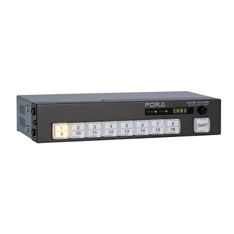
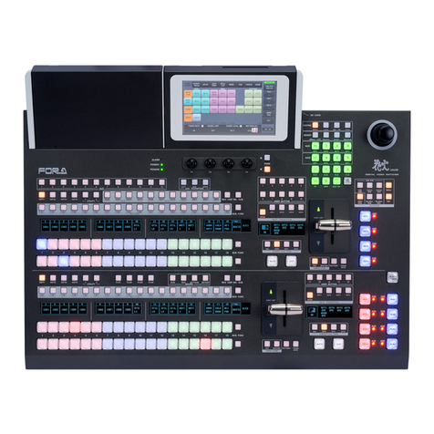
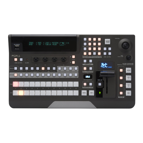
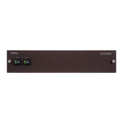
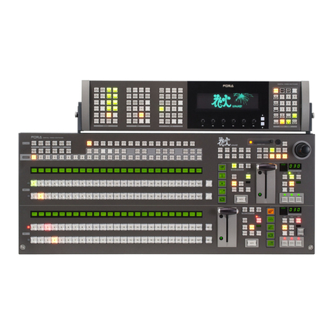
FOR-A HVS-1000HS User manual

HVS-1000HS
Digital Video Switcher
HVS-1000EOU
Hanabi Operation Unit
2nd Edition-Rev.4
OPERATION
MANUAL


Precautions
Important Safety Warnings
[Power]
Operate unit only on the specified supply voltage.
Disconnect power cord by connector only. Do not pull on cable portion.
Do not place or drop heavy or sharp-edged objects on power cord. A damaged cord
can cause fire or electrical shock hazards. Regularly check power cord for
excessive wear or damage to avoid possible fire / electrical hazards.
[Grounding]
Ensure unit is properly grounded at all times to prevent electrical shock hazard.
Do not ground the unit to gas lines, units, or fixtures of an explosive or dangerous
nature.
[Operation]
Do not operate unit in hazardous or potentially explosive atmospheres. Doing so
could result in fire, explosion, or other dangerous results.
Do not allow liquids, metal pieces, or other foreign materials to enter the unit. Doing
so could result in fire, other hazards, or unit malfunction.
If foreign material does enter the unit, turn power off and disconnect power cord
immediately. Remove material and contact authorized service representative if
damage has occurred.
Caution
Hazard
Stop
Caution
Hazard
Hazard

[Circuitry Access]
Do not remove covers, panels, casing, or access circuitry with power applied to the
unit! Turn power off and disconnect power cord prior to removal. Internal servicing /
adjustment of unit should only be performed by qualified personnel.
Do not touch any parts / circuitry with a high heat factor.
Capacitors can retain enough electric charge to cause mild to serious shock, even
after power is disconnected. Capacitors associated with the power supply are
especially hazardous. Avoid contact with any capacitors.
Unit should not be operated or stored with cover, panels, and / or casing removed.
Operating unit with circuitry exposed could result in electric shock / fire hazards or
unit malfunction.
[Potential Hazards]
If abnormal smells or noises are noticed coming from the unit, turn power off
immediately and disconnect power cord to avoid potentially hazardous conditions. If
problems similar to above occur, contact authorized service representative before
attempting to again operate unit.
[Fuse]
If this product is equipped with a fuse, fuse replacement should only be performed
by qualified personnel. Power off equipment and disconnect power cord prior to
replacement. Replace only with fuse of same type, voltage rating, and current rating
as specified for the unit.
[Backup Battery]
If this product contains a memory backup battery (either dry cell or rechargeable)
and when it is necessary to replace the battery, have work done by the shop where
you purchased the product.
Caution
Caution
Caution
Hazard
Stop

Upon Receipt
Unpacking
The HVS-1000HS and any of its options you may have purchased are fully inspected and
adjusted prior to shipment and can be operated immediately upon completing all required
connections and operational settings. Check your received items against the packing lists
below.
MU Box Contents
ITEM QTY REMARKS
HVS-1000HS MU 1 HVS-1000 Series main processing unit
AC Cord 1 For AC power connection
Rack Mount Brackets 1 pr. Rack mounting to EIA standard type
OU Box Contents
HVS-1000EOU 1 HVS-1000 Series Operation Unit for Editing
Control Cable 1 For connection between MU and OU, 10m (PC-3108)
AC Cord 1 For AC power connection
Memory Card 1 Compact Flash memory card
Operation Manual 1
Internal Options
HVS-1000HSDI 1-2 For addition of 4 signal inputs (max 2 cards)
HVS-1000HSCR 1 For addition of 4 signal inputs + UTL-IN
HVS-1000HSDO 1 For addition of 3 signal outputs
HVS-KEYER (*1) 1-2 For addition of a keyer (max 2 cards)
HVS-KYCC (*1) 1-2 For addition of a keyer with color corrector (max 2 cards)
DVE-1000HS (*2) 1 Standard DVE unit (HD/SD switchable)
DVE-1000HSA (*2) 1 Advanced DVE unit (HD/SD switchable)
HVS-ARCNET 1 ARCNET board
HVS-1000PSM 1 Modular redundant power supply for MU
HVS-1000PSO 1 Modular redundant power supply for OU
External Options
HVS-AUX16 (*3) 1-10 For addition of auxiliary controls
(common use with HVS-3100/3000H/S)
HVS-AUXRK 1
For HVS-AUX16 remote connection use
(common use with HVS-3100/3000H/S)
HVS-TALR20/32 (*4) 1-5 For tally signal use (relay type),
(common use with HVS-3100/3000H/S)
HVS-TALOC20/32 (*4) 1-5 For tally signal use (open collector type),
(common use with HVS-3100/3000H/S)
BNC cable 1 For Arcnet connection, 10m (5C2V 75ohm)
Memory Card 1 Compact Flash memory card
(*1) Up to two HVS-KEYER or HVS-KYCC optional boards can be installed to the MU. HVS-1000CC
(software option) is necessary for HVS-KYCC.
(*2) Either DVE-1000HS or DVE-1000HSA can be installed to the MU. (Both not available.)
(*3) HVS-ARCNET optional board is necessary for HVS-AUX16 use.
(*4) A multiple Tally unit configuration possible; up to 5 units max.
Each optional device (except factory installed ones) included the specific operation or installation manuals.

Check
Check to ensure no damage has occurred during shipment. If damage has occurred, or items
are missing, inform your supplier immediately.
Rack Mounting
The HVS-1000HS can be mounted to EIA standard rack units. When rack mounting a unit,
remove the rubber feet and use the accessory rack mount brackets (rack ears).

Table of Contents
1. Prior to Starting...........................................................................................................................1
1-1. Welcome.............................................................................................................................1
1-2. About HVS-1000 Series Switchers......................................................................................1
1-3. About This Manual..............................................................................................................2
2. Panel Description........................................................................................................................3
2-1. Operation Unit.....................................................................................................................3
2-1-1. Operation Panel..........................................................................................................3
2-1-2. Rear Panel..................................................................................................................4
2-2. Main Unit.............................................................................................................................5
2-2-1. Front Panel.................................................................................................................5
2-2-2. Rear Panel..................................................................................................................6
2-2-3. Interfaces....................................................................................................................7
2-2-4. MU Rear Panel Cards...............................................................................................11
3. Connection................................................................................................................................12
3-1. Basic Connection..............................................................................................................12
3-2. Optional Configuration......................................................................................................13
3-3. Aspect/Format Selection...................................................................................................14
4. Menu Operations ......................................................................................................................15
4-1. Menu Control Sections......................................................................................................15
4-2. Making Settings ................................................................................................................15
4-2-1. Selecting Needed Menu............................................................................................15
4-2-2. Changing Parameter Values.....................................................................................17
4-2-3. Confirmation Needed Parameters.............................................................................17
4-2-4. Keypad Input.............................................................................................................18
4-2-5. Joystick Input............................................................................................................19
4-2-6. ON/OFF Button.........................................................................................................19
4-3. Menu Display Descriptions ...............................................................................................20
4-3-1. Menu Select Section.................................................................................................20
4-3-2. Menu Access Shortcuts ............................................................................................21
4-3-3. User Buttons.............................................................................................................22
4-4. Returning to Default..........................................................................................................24
4-4-1. Returning Each Parameter to Default.......................................................................24
4-4-2. Returning Menus to Default......................................................................................24
4-4-3. Returning to User Default .........................................................................................25
5. Selecting Input Signals .............................................................................................................26
5-1. Bus Button Indications......................................................................................................26
5-1-1. Color Indication.........................................................................................................26
5-1-2. Flip-Flop....................................................................................................................26
5-2. MATT................................................................................................................................27
5-3. Input Signals.....................................................................................................................29
5-3-1. Signal Name .............................................................................................................29
5-3-2. Selecting M/E Bus Signals........................................................................................30
5-3-3. Bus Signal Assignment and Inhibit Settings..............................................................32
6. Selecting Where Outputs Appear..............................................................................................33
6-1. Selecting Signals ..............................................................................................................33
6-1-1. Selecting Preview Output..........................................................................................34
6-1-2. Selecting AUX / INPUT PREV / CLEAN Output........................................................34

7. Transition Operations ...............................................................................................................37
7-1. BLACK Transitions...........................................................................................................38
7-2. DSK Transitions................................................................................................................38
7-3. BKGD, KEY1, and KEY2 Transitions................................................................................39
7-3-1. CUT Transition .........................................................................................................39
7-3-2. MIX, FAM and NAM..................................................................................................40
7-3-3. WIPE Transition........................................................................................................41
7-3-4. DVE Transition .........................................................................................................42
7-4. Additional Transition Settings ........................................................................................... 44
7-4-1. Fader Limit ...............................................................................................................44
7-4-2. Fader Operational Settings ......................................................................................45
7-4-3. Transition Rate.........................................................................................................45
7-4-4. AUTO Button Operational Setting............................................................................. 46
7-5. Selecting A Pattern...........................................................................................................47
7-5-1. Checking and Setting Patterns.................................................................................47
7-5-2. Pattern List Pop-up Menu.........................................................................................47
7-5-3. Direct Pattern Function.............................................................................................48
7-6. Modifying A WIPE Pattern................................................................................................ 49
7-6-1. Making Modify Settings............................................................................................49
7-6-2. Initializing WIPE MODIFY Menu...............................................................................49
7-6-3. WIPE MODIFY Menu ............................................................................................... 50
7-7. DVE Pattern Modify..........................................................................................................51
7-7-1. Making Modify Settings............................................................................................51
7-7-2. Initializing DVE MODIFY Menu ................................................................................ 53
7-7-3. DVE Pattern Modify Setting Example....................................................................... 53
7-7-4. Saving Modified DVE pattern as User Pattern..........................................................54
8. User Patterns ...........................................................................................................................55
8-1. About the User Patterns...................................................................................................55
8-2. Editing User Patterns .......................................................................................................56
8-2-1. Displaying the USER PATTERN Menu.....................................................................57
8-2-2. PROTECT Setting.................................................................................................... 58
8-2-3. Setting the Keypad to USER PATTERN Editing.......................................................58
8-2-4. Selecting the DVE Channel (Menu/Keypad).............................................................59
8-2-5. Creating New Keyframes ......................................................................................... 59
8-2-6. Selecting Keyframes (Menu/Keypad).......................................................................60
8-2-7. Adding and Overwriting Keyframes (Keypad)........................................................... 60
8-2-8. Copying and Pasting Keyframes (Keypad)...............................................................61
8-2-9. Deleting Keyframes (Keypad)...................................................................................61
8-2-10. Selecting the Interpolation Mode (Menu)................................................................61
8-2-11. Setting the Keyframe Duration................................................................................62
8-2-12. Previewing User Patterns.......................................................................................62
8-2-13. Deleting User Patterns ...........................................................................................62
8-2-14. Exiting User Pattern Editing ...................................................................................63
8-3. Executing User Patterns...................................................................................................63
8-4. Modifying Created Keyframes..........................................................................................63
9. LINE DVE.................................................................................................................................64
9-1. Assigning LINE DVE.........................................................................................................64
9-1-1. Assigning to PGM bus.............................................................................................. 64
9-1-2. Assigning to PST bus ...............................................................................................65
9-1-3. Assigning to KEY1 or KEY2 bus............................................................................... 65
9-2. DVE Options ....................................................................................................................66
9-3. LINE DVE Modify Setting Example ..................................................................................67
9-4. DVE MODIFY Menu.........................................................................................................68
9-4-1. Position and Size......................................................................................................69
9-4-2. DVE STILL (DVE. Ver.2.00 or later) ......................................................................... 71
9-4-3. PERSPECTIVE.........................................................................................................71
9-4-4. CROP .......................................................................................................................71
9-4-5. WARP (Option) .........................................................................................................72
9-4-6. BORDER ..................................................................................................................73
9-4-7. TRAIL / SHADOW.....................................................................................................74
9-4-8. SUB EFFECT ...........................................................................................................74
9-4-9. HILITE.......................................................................................................................75
10. Examples of Effect Operations................................................................................................76
10-1. Effects using WIPE Modify..............................................................................................76
10-1-1. Jagged Edge...........................................................................................................76
10-2. Effects Using Still Store...................................................................................................77
10-2-1. Motion Blur..............................................................................................................77
10-2-2. Animation Logo.......................................................................................................78
10-3. Effects Using DVE ..........................................................................................................80
10-3-1. WIPE Switchover In A Video Wall (LINE DVE)........................................................80
10-3-2. DVE MULTI MOVE (DVE Pattern Modify)...............................................................81
10-3-3. PIZZA BOX (DVE Pattern Modify)...........................................................................82
11. Key Operations .......................................................................................................................84
11-1. Luminance Key Setup.....................................................................................................85
11-2. Bus Key Setup ................................................................................................................86
11-3. Available Signals.............................................................................................................88
11-3-1. KEY MATT ..............................................................................................................88
11-4. Key Adjustments .............................................................................................................89
11-4-1. TRANSPARENCY...................................................................................................89
11-4-2. FAM ON/OFF..........................................................................................................89
11-4-3. CLIP and GAIN .......................................................................................................89
11-4-4. Gain Clip Processing Settings.................................................................................90
11-5. Key Mask and Invert .......................................................................................................91
11-5-1. Key Invert................................................................................................................91
11-5-2. Box Mask ................................................................................................................92
11-5-3. DSK Mask (Option).................................................................................................93
11-6. Edge and Shadow (Option).............................................................................................94
11-7. Key Priority (Option)........................................................................................................95
12. Chromakeys............................................................................................................................96
12-1. Chromakey Setup Flow...................................................................................................96
12-2. Chromakey Setup...........................................................................................................97
12-2-1. Auto Setup..............................................................................................................97
12-2-2. Chromakey Adjustment...........................................................................................98
13. Color Correction (Option)......................................................................................................100
13-1. Color Correction Overview............................................................................................100
13-2. Color Corrector Specifications ......................................................................................100
13-3. Color Correction Flow...................................................................................................101
13-4. Assigning Color Corrector Signals ................................................................................102
13-5. Proc Amp......................................................................................................................103
13-6. Color Correction............................................................................................................103
13-6-1. Balanced Mode and Differential Mode..................................................................104
13-6-2. Gamma Curve.......................................................................................................105
13-7. Clip Adjustment.............................................................................................................106
13-7-1. YPbPr Mode and RGB Mode................................................................................107
13-8. Assigning User Button Signals......................................................................................109
13-8-1. Assigning CC Channels to User Buttons...............................................................109
13-8-2. Selecting a Signal.................................................................................................109

14. Still Store...............................................................................................................................110
14-1. Still Capture and Save...................................................................................................110
14-2. Assigning Bus................................................................................................................110
15. Event Memory.......................................................................................................................111
15-1. Saving Events ...............................................................................................................111
15-2. Recalling Events............................................................................................................112
15-2-1. Recalling Events Using Keypad (0-199)................................................................112
15-2-2. Recalling Events Using USER Buttons (0-7).........................................................113
16. Sequence Operation .............................................................................................................114
16-1. Overview of Sequence Function....................................................................................114
16-2. Editing Sequences ........................................................................................................115
16-2-1. Displaying the SEQUENCE Menu.........................................................................116
16-2-2. PROTECT Setting (Menu).....................................................................................117
16-2-3. Setting the Keypad to SEQUENCE Editing...........................................................118
16-2-4. Creating New Steps (Keypad)...............................................................................119
16-2-5. Selecting Steps (Menu/Keypad)............................................................................119
16-2-6. Adding and Overwriting Steps (Keypad)................................................................119
16-2-7. Copying and Pasting Steps (Keypad)...................................................................120
16-2-8. Deleting Steps (Keypad)....................................................................................... 120
16-2-9. Selecting the Interpolation Mode (Menu)..............................................................120
16-2-10. Setting the Duration (Menu) ............................................................................... 120
16-2-11. Deleting Sequences ...........................................................................................121
16-2-12. Exiting Sequence Editing ................................................................................... 121
16-2-13. Backing Up Sequence Data ...............................................................................121
16-3. Playing Back Sequences.............................................................................................. 122
16-3-1. Sequence AUTO PLAY......................................................................................... 122
16-3-2. Setting Crosspoint Playback ................................................................................123
16-3-3. Bus Settings......................................................................................................... 123
16-3-4. Selecting Loop Playback...................................................................................... 123
16-3-5. Using Fader Link for Sequence Playback ............................................................ 124
16-3-6. Break Settings during Fader Link......................................................................... 125
17. File Operations.....................................................................................................................126
17-1. CF Card........................................................................................................................126
17-2. Saving Data to CF Cards..............................................................................................126
17-3. Downloading from CF Cards........................................................................................127
17-4. Deleting Memory Card Files......................................................................................... 128
17-5. Renaming Saved Files.................................................................................................129
17-6. Aborting File Transfer...................................................................................................129
18. Additional Features...............................................................................................................130
18-1. OU Setup .....................................................................................................................130
18-1-1. Display Brightness and Contrast.......................................................................... 130
18-1-2. Fader Lever Response.........................................................................................130
18-1-3. Screen Contrast ...................................................................................................130
18-1-4. Menu Shift Button Response................................................................................131
18-1-5. Warning Buzzer.................................................................................................... 131
18-1-6. Joystick Response ............................................................................................... 131
18-1-7. Screen Saver........................................................................................................ 132
18-1-8. Date/Time Setting................................................................................................. 132
18-1-9. Mode.................................................................................................................... 132
18-2. Advanced Signal Settings............................................................................................. 133
18-2-1. Selecting and Adjusting Sync Signal ....................................................................133
18-2-2. Safety Area Markers............................................................................................. 134
18-2-3. MATT CLIP........................................................................................................... 135

18-2-4. Ancillary Data........................................................................................................136
18-3. User Default..................................................................................................................137
18-4. Data Recovery..............................................................................................................137
18-5. Reboot and Initialization................................................................................................138
18-5-1. Initializing the System...........................................................................................138
18-5-2. Initializing OU Mode MENU ..................................................................................138
18-5-3. System Reboot .....................................................................................................138
19. Interface Settings..................................................................................................................139
19-1. GPI and Tally Control....................................................................................................139
19-1-1. GPI IN Free Assignments .....................................................................................139
19-1-2. GPI/TALLY OUT Free Assignments ......................................................................141
19-1-3. TALLY Free Assignments......................................................................................142
19-2. Editor Control................................................................................................................144
19-3. Network Settings...........................................................................................................145
19-3-1. Arcnet (Option)......................................................................................................145
19-3-2. Ethernet (Option) ..................................................................................................147
19-4. Upgrading Operational Version.....................................................................................148
19-4-1. How to Verify Version............................................................................................148
19-4-2. Upgrade Procedure...............................................................................................148
19-4-3. Saving Setting Data..............................................................................................149
19-4-4. To Upgrade MU.....................................................................................................149
19-4-5. To Upgrade OU.....................................................................................................150
19-4-6. Loading Setting Data ............................................................................................150
19-5. Changing Signal Format Data (DVE Ver.1)...................................................................151
19-5-1. Before starting.......................................................................................................151
19-5-2. Checking the signal format data............................................................................151
19-5-3. Changing the format data .....................................................................................152
19-6. Upgrading DVE Card (DVE Ver.2) ................................................................................154
19-6-1. Checking the DVE Card Version...........................................................................154
19-6-2. Upgrading the DVE Card ......................................................................................155
20. Specifications and Dimensions .............................................................................................157
20-1. System Specifications...................................................................................................157
20-1-1. HVS-1000HS (HD mode)......................................................................................157
20-1-2. HVS-1000HS (SD mode)......................................................................................158
20-1-3. HVS-1000EOU......................................................................................................159
20-2. External Dimensions.....................................................................................................160
20-2-1. HVS-1000HS ........................................................................................................160
20-2-2. HVS-1000EOU......................................................................................................161
Appendix 1. Menu List ....................................................................................................................1
1-1. STATUS menu....................................................................................................................1
1-2. SETUP menu......................................................................................................................2
1-3. COLOR CORRECTION menu............................................................................................8
1-4. EDITOR menu ....................................................................................................................9
1-5. MATT menu ........................................................................................................................9
1-6. STILL menu ......................................................................................................................10
1-7. FILE menu........................................................................................................................11
1-8. TRANSITION menu..........................................................................................................12
1-9. WIPE MODIFY menu........................................................................................................13
1-10. DSK menu ......................................................................................................................14
1-11. KEY1 and KEY2 menu....................................................................................................15
1-12. DVE MODIFY menu........................................................................................................18
1-13. USER PATTERN menu...................................................................................................22
1-14. SEQUENCE menu..........................................................................................................22

Appendix 2. Available File List......................................................................................................23
Appendix 3. WIPE Pattern List.....................................................................................................24
Appendix 4. DVE Pattern List.......................................................................................................25
Appendix 5. User Preset Patterns (50 patterns)........................................................................... 27

1
1. Prior to Starting
1-1. Welcome
Congratulations! By purchasing the Hanabi HVS-1000 series switcher you have entered the
world of FOR-A and its many innovative products. Thank you for your patronage and we hope
you will turn to FOR-A products again and again to satisfy your video and audio needs.
FOR-A provides a wide range of products, from basic support units to complex system
controllers, which have been increasingly joined by products for computer video based systems.
Whatever your needs, talk to your FOR-A representative. We will do our best to be of continuing
service to you.
1-2. About HVS-1000 Series Switchers
The Hanabi HVS-1000 series switchers are 1M/E low-cost, compact digital switchers that are
ideal for operations and mobile applications in limited space such as production, mobile relay
vans, and live signal distribution. These HD/SD switchable switchers have multi bit-rate /
multi-format capability supporting SDI HDTV and SDTV signals for usage in a wide range of
applications.
Up to 21 sources and 2 matt signals can be assigned to an M/E bus, including built-in still store
for 4 images and standard 8 primary inputs, expandable to a maximum of 17 inputs with the
addition of an option board. The standard configuration includes five outputs -- two program
outputs, a preview output, an auxiliary output, and input preview output. Available expansion
options include three auxiliary outputs. The operation panel keeps the same ease of operation of
the HVS-3000 series but now includes a CF card reader drive in the standard system for image
file transfer and backup of settings.
In addition to mix and wipe transitions, 2D DVE are available as standard, and DVE upgrades
are also available. The HVS-1000 also features distinctive effects not available in the HVS-3000,
including motion blur and logo animations using still store and mix and wipe transitions in a
modified floating DVE wall.
This HVS-1000 series switcher, the HVS-1000EOU, is designed as an operation unit specifically
for editing, and it provides the same ease of operation and functions of the previous FOR-A
VPS-400D switcher. In the standard configuration, the HVS-1000EOU has an editor connecting
facility, 200-event memory and user programmable 3D effects and sequence operation
capabilities.
Features
Full option system supports up to 16 HD/SD SDI video signal inputs and 1 camera return
input for a total of 17 inputs. Up to 8 signal outputs available; 2 PGM, 1 PREV, 1 Input Prev
and 4 AUX outputs
10-bit 4:2:2 digital component signal processing.
Support for multi bit-rate / multi-format digital component input signals. Easy signal
switchover between HD multi-format (1080/60i, 1080/24p, 720/60p, etc.) and SD format
(NTSC/PAL) signals by using the operation panel menu settings. In addition to standard 16:9
(for HDTV) and 4:3 (for SDTV), 4:3 is available for HDTV and Letterbox and Squeeze formats
are available for SDTV.
One downstream keyer is available in the standard configuration, and 2 keyers with
chromakey functions are available in the optional configuration.
Key masks are provided in standard configuration. Edge and shadow effects and priority
change are available for the 2 optional keyers.

2
HDTV tri-sync and analog black burst input signals for system synchronization and
dedicated connectors with loopthrough output for each sync signal.
MIX, FAM and NAM transitions available with 100 WIPE patterns in standard configuration,
expandable to 120 DVE patterns with option.
Provides 50 user programmable 3D effects patterns. Up to 50 keyframes available for each.
Versatile 4 channel (for S DTV) or 2-channel (for HDTV) DVE modify operations possible
with optional DVE board.
Up to 6 signal layers, including PGM, PST, 3 keys and 3D effect BKGD buses, are available
in the full option system.
Includes 4 still stores and 2 bus matt signal generators. Incorporates logo animation function
using still store.
200 event internal memory for saving and reading of setting data.
20 sequence memory. Up to 50 steps available for each.
Built-in memory card drive for uploading and downloading of setting files and image
sources.
Configuration of up to 5 MU/OU and AUX units possible with optionalArcnet board.
Standard system includes RS-422 GPI IN and GPI/TALLY OUT ports. Up to 5 Hanabi series
tally units (HVS-TALOC, HVS-TALR) can be used in RS-422 cascade connection.
Capable of various GPI input/output controls using GPI IN and GPI/TALLY OUT ports.
Supports redundant power supply for main unit and operation unit.
Main unit is a compact EIA 2RU standard size.
1-3. About This Manual
This manual is intended to help the user easily operate the Hanabi series switchers and make
full use of their functions during operations. Before configuring or operating your system, read
this operation manual thoroughly to ensure you understand the product. After reading, it is
important to keep this manual in a safe place and available for future reference.
Font Conventions
The following conventions are used through out this manual:
Boxed text (for example MATT) is used for OU buttons.
Shaded text (such as OFF) is used for the setting parameters and values in the menus.

3
2. Panel Description
2-1. Operation Unit
2-1-1. Operation Panel
Item Description Function
A Operational menu selection Selects menu or operational parameters
displayed at B.
B Menu display / controls LCD menu / parameters display and controls
For number input / operational data adjust.
C Keypad / Event control section For event save / recall operations.
D Joystick control section For number input.
E Memory card drive For data upload / download (CF card)
F User buttons For menu shortcut and function assignments.
AUX/KEY output selection Selects whereAUX output or key use signals in
M/E inputs appear.
G M/E bus for AUX and KEY For key insert or AUX signal source selection.
H M/E bus for background For background signal source selection.
I Transition control section For transition setup of background and key
layers.
Y
WIPE POS
Z
EDITOR
STILL
USER
ON/OFF
EDGE1
KEY1
DVE
EDGE2
KEY2
WARP
SHADOW
OPT SEL
DSK
CROP
SHIFTSUB E FF
(BORDER)
(MASK2) (MASK)
(TRAIL)
(HILITE)
(SHA DOW2)(SHADOW 1)
(FREEZE)
USER
1USER
2USER
3USER
4
BLACK
BLACK 1
1
2
8
3
7
4
6
5
5
6
4
7
3
8
2
MATT
MATT
SHIFT
SHIFT
X
(MOSAIC)
7
+/-
89
456
123
0
AUTO
TRANSITION TYPE
NEXT TRANSITION
NOR REVNOR/REV
8765
DEFDVE POS
DVEROT
STATUS WIPE MATT
(BORDER) SEQ EVENT DVE CH DIRECT PATT
(SETUP) (PATTERNSEL)
(FILE) (MASK1)
(SEQ)
DSK
TRANS
LCD
BLACK
TRANS
F1 F2 F3 F4 F5
MEMORY CARD
ACCESS
BKGD KEY1 KEY2 DSK
TRANSITION
RATE
BLACK
DVE
DVE
AUTO C K MEN U
MIX
WIPE
FAM
NAM
MIX
WIPE
ON
MIX
WIPE
ON
KEY2KEY1BKGD
KEY1
OVER
SEQL INKFADERLIM
DVE DVE DVE
DVE
(NAM)
WIPE
(FAM)
MIX
CUT
TRANS
CUT
MIX
HVS-1000
DIGITALVIDEOSWITCHER
TRANS
STORE
RECALL
(CANCEL)
CLEAR SHIFT ENTER
(PLAY)(PAUSE)
USERUSERUSERUSER
BLACK 12345678
MATT SHIFTDVE
BUS
SELECT
KEY/
AUX
KEY1 KEY2 DSK EFFECT BK AUX1 AUX2 AUX3 AUX4 INPUTPREV PGM PREV CLEAN DVE KEY UTILITY IN

4
2-1-2. Rear Panel
Item Description Function
A TO MU TO MU connector (PC-3108, 15-pin D-sub, female)
B POWER1 For AC input connection to power supply unit 1 (standard PS)
(AC100V-240V 50/60Hz).
C POWER2 For AC input connection to power supply unit 2 (optional PS)
(AC100V-240V 50/60Hz).
D RESET Reset switch for MU/OU.
E ARCNET BNC connector with loopthrough output for Arcnet use (option).
F SERVICE Do not use.
G Ground Terminal Used to ground unit for electrical protection.
TO MU
ON
OFF
ARCNET SERVICE I/O
OFF
ON
RESET
RATING LABEL
POWER 1POWER 2
AC100-2 40V ~50/6 0Hz INAC100-240V ~50/60Hz IN

5
2-2. Main Unit
2-2-1. Front Panel
Item Description Function
A POWER 1 Used to switch power supply unit 1 ON / OFF.
DC power alarm
indicator for PS1 The green power indicator lights on if the power supply unit
1 is operating normally. The indicator is not lit if an alarm
condition occurs.
B MU fan alarm
indicator The red fan alarm indicator lights on if any fan of the MU
(unit fan and fans for PS1 and PS2) fails. The indicator is
not lit when the fans are operating normally.
C POWER 2 Used to switch power supply unit 2 ON / OFF.
DC power alarm
indicator for PS2 The green power indicator lights on if the power supply unit
2 is operating normally. The indicator is not lit if an alarm
condition occurs.
D MU fan alarm
indicator The red fan alarm indicator lights on if any fan of the MU
(unit fan and fans for PS1 and PS2) fails. The indicator is
not lit when the fans are operating normally.
IMPORTANT
If alarm indication continues to appear, check out each unit status using the STATUS
menu (To open the STATUS menu, press the STATUS button in the menu select
section.), then power the unit off and contact your FOR-A supplier for advice.
If you have both the accessory and optional power supplies installed, you will need to
turn at least one power switch ON before you can use your MU. Normally, both
power switches should be set to ON at the same time if you want power backup
protection should one of the power units fail during operation. Note that if both
power units are set to on and one unit fails, the unit with problem will be powered
off automatically.
HANABI
ON
POWER 1
OFF
POWER 2
ON
OFF
DC
FAN
FAN
DC
DIGITAL VIDEO SWITCHER
HVS-1000HS

6
2-2-2. Rear Panel
Item Description Function
PGM1, PGM2 For program outputs, BNC.
PREV For preview output, BNC.
AUX1 For auxiliary output, BNC.
INPUT PREV For loopthrough output from INPUT PREV input signal, BNC.
A
AUX2-AUX4 For auxiliary outputs (option), BNC.
1-8 For serial digital component input signal connection, BNC.
9-16 For serial digital component input signal connection (option),
BNC.
B
UTL-IN For serial digital component input signal connection (option),
BNC.
C LAN
(10/100BASE-T) For 10BASE-T/100BASE-TX Ethernet connection (option),
RJ-45.
D ARCNET For Arcnet connection (option), BNC.
E EDITOR For Editor connection, 9-pin D-sub (female).
F RS-422 For tally unit connection, 9-pin D-sub (female).
G OU For OU connection use, 15-pin D-sub (female).
H ALARM For alarm output, 9-pin D-sub (female).
I GPI IN For GPI operation control input, 15-pin D-sub (female).
J GPI/TALLY OUT For GPI and tally operation control output, 25-pin D-sub
(female).
TRI SYNC IN For tri-sync genlock reference signal input, BNC with
loopthrough.
BB IN For black burst genlock reference signal input, BNC with
loopthrough.
K
REF OUT For reference signal output, tri-sync and BB signal selectable in
the menu.
L AC IN1 For AC input connection to power supply unit 1 (standard PS)
M Ground terminal Used to ground unit for electrical protection.
N AC IN2 For AC input connection to power supply unit 2 (optional PS)
* See section 3 “Connection“ for more details about system configurations.
RATING LABEL
1
2
GPI/TALLYOUTGPI INOUEDITOR
CPU
LAN
(10/100BASE-T)
ARCNET TRI SYNC INALARMRS-422 BB IN REFOUT
12
GL
OUTPUT
INPUTPREV
133
INPUT
UTLIN41 1412 15 169811106257
AC100-240V ~ 5 0/60Hz IN
AUX4AUX3AUX2 PGM 1 PGM 2 AUX1PREV

7
2-2-3. Interfaces
ALARM Connector
Pin Assignment Table
Pin No. Signal Name Description
1 FAN ALARM OUT Fan failure alarm. Normally open.
2 POWER ALARM OUT Power supply failure alarm. Normally close.
3 N/C Not used
4 N/C Not used
5 RESET IN External reset input. Active low initiate.
6 FAN ALARM COMMON Fan alarm common.
7 POWER ALARM
COMMON Power supply alarm common.
8 GND Common ground
9 GND Common ground
Cable Connectors
9-pin D-sub connector (male) with inch security lock screws needed for user cable
fabrication.
Fan alarm
Pins 1, 6 remain OPEN during normal operation. If fan failure occurs at HVS-1000HS side,
pins 1, 6 will short and fan alarm signal output occurs.
Power supply alarm
Pins 2, 7 remain OPEN during normal operation. If a power supply failure occurs, pins 2, 7
will short and power supply alarm signal output occurs.
External reset
External reset signal input to pin 5, shorts pin 5 to pin 9.MU reset occurs when short initiated.
*Max. contact load of 0.5A DC.

8
EDITOR Connector
Pin Assignment Table (9-pin D-sub female)
Pin No. Signal Name Description
1 FG Frame ground
2 T- Transmit data (-)
3 R+ Receive data (+)
4 SG Signal ground
5 - Not used
6 SG Signal ground
7 T+ Transmit data (+)
8 R- Receive data (-)
9 FG Frame ground
Cable Connectors
9-pin D-sub connector (male) with inch security lock screws needed for user cable
fabrication.
RS-422 Connector
Pin Assignment Table (9-pin D-sub female)
Pin No. Signal Name Description
1 FG Frame ground
2 R- Receive data (-)
3 T+ Transmit data (+)
4 SG Signal ground
5 - Not used
6 SG Signal ground
7 R+ Receive data (+)
8 T- Transmit data (-)
9 FG Frame ground
Cable Connectors
9-pin D-sub connector (male) with inch security lock screws needed for user cable
fabrication.
This manual suits for next models
1
Table of contents
Other FOR-A Switch manuals

FOR-A
FOR-A VSF-6496 User manual

FOR-A
FOR-A MFR-6100 User manual

FOR-A
FOR-A HVS-100 User manual

FOR-A
FOR-A RS-HD808 User manual

FOR-A
FOR-A HVS-350HS User manual

FOR-A
FOR-A HVS-3800HS User manual

FOR-A
FOR-A HVS-3800HS Quick setup guide

FOR-A
FOR-A HVS-300HS User manual

FOR-A
FOR-A HVS-492OU User manual

FOR-A
FOR-A MFR-6000R User manual

FOR-A
FOR-A HVS-AUX8 User manual

FOR-A
FOR-A HVS-6000 User manual

FOR-A
FOR-A MFR-6000 User manual

FOR-A
FOR-A Multi Viewer MV-40F(A) User manual

FOR-A
FOR-A MFR-3000 User manual

FOR-A
FOR-A VPS-700 MU User manual

FOR-A
FOR-A HVS-390HS User manual

FOR-A
FOR-A HVS-190S User manual

FOR-A
FOR-A MFR-4000 User manual

FOR-A
FOR-A MFR-1616 User manual