Forest SDA46GBARFP User manual
Making British gardens great
Thank you for purchasing your garden bar from Forest Garden. Simply follow these step-by-step instructions and
our top tips, and you’ll be enjoying your garden bar for many years to come. If you have any questions or need
advice, our friendly team is here to help.
ISSUE: 0122
SHIPLAP GARDEN BAR
INSTRUCTIONS (6x4)
Missing something or need more information?
Call our aftersales team on
0333 321 3142
Visit our website for spare instructions and
more information
www.forestgarden.co.uk
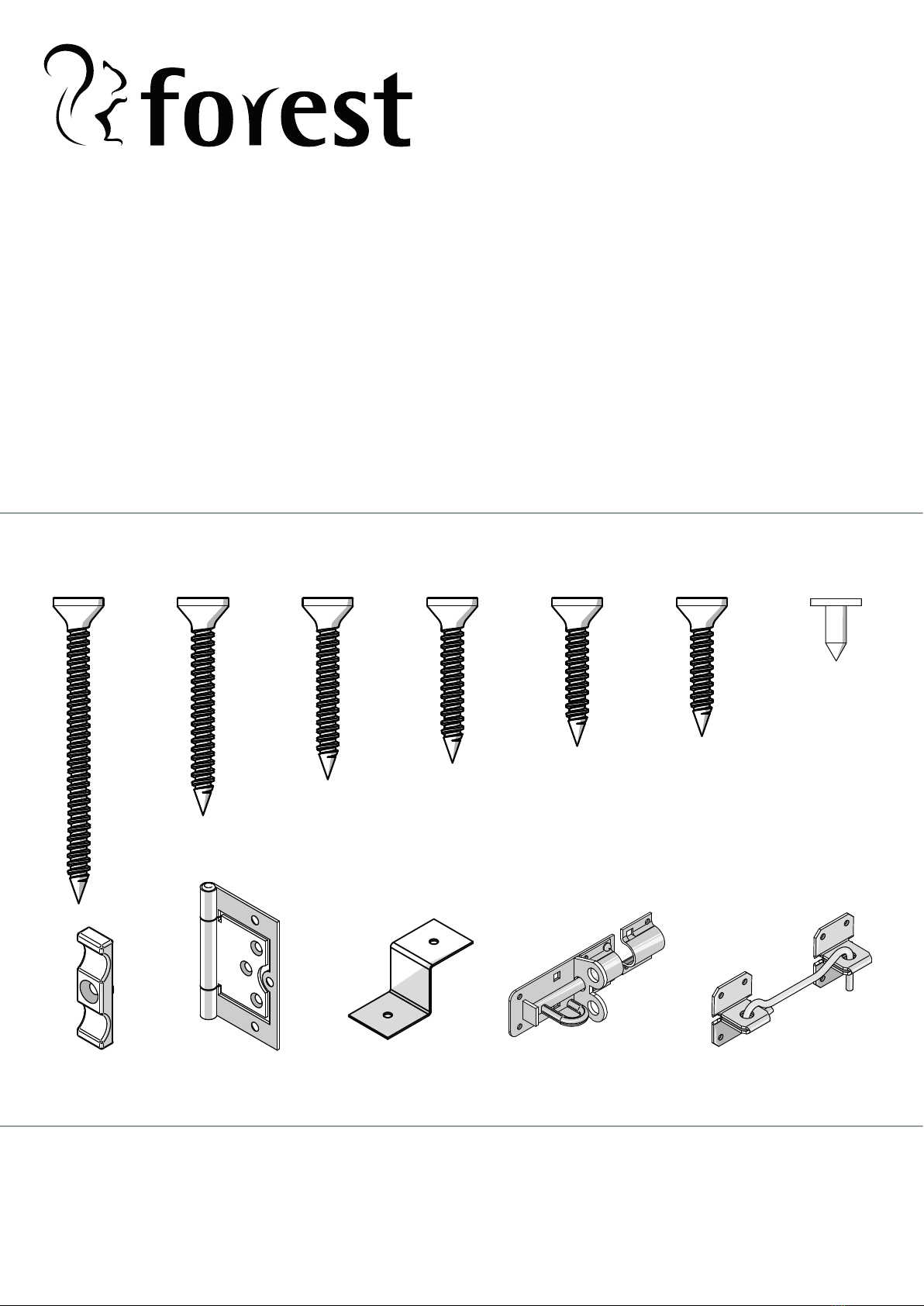
FIXING PACK CONTAINS:
4x50mm Screws
QTY: 58
5x70mm Screws
QTY: 12
4x40mm Screws
QTY: 12
3.5x30mm Screws
QTY: 109
3.5x25mm Screws
QTY: 112
Felt Tacks
QTY: 124
Flush Hinges
QTY: 10
Padbolt
QTY: 1
Turn Buttons
QTY: 4
6x120mm Screws
QTY: 3
Z-Brackets(28mm)
QTY: 14
Hook & Eye
QTY: 2
FIXING PACK CODE: SDA46GBARFP
Forest Garden, Oak Drive, Hartlebury Trading Estate, Hartlebury, Worcestershire, DY10 4JB
EU Authorised Representative: Authorised Representative Service, 77 Camden Street Lower Dublin, D02 XE80, Ireland
2
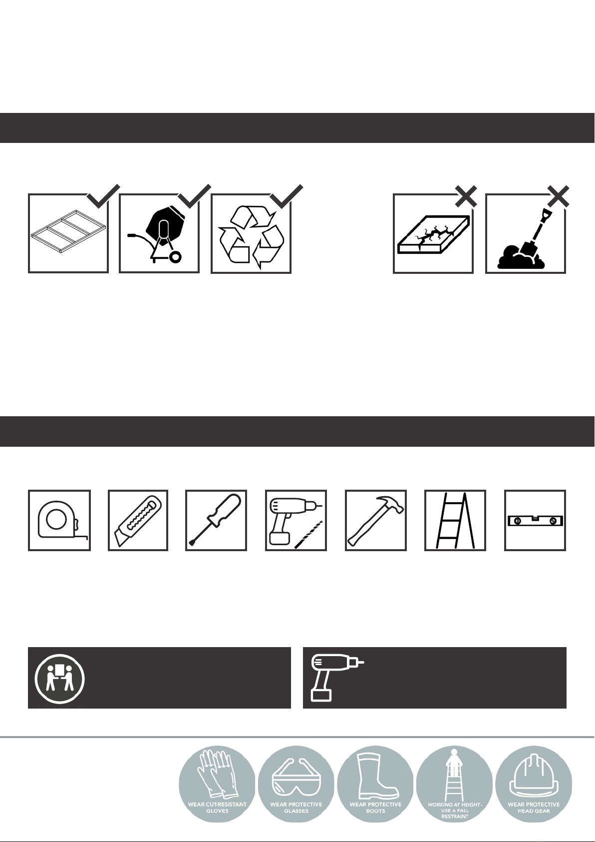
HEALTH & SAFETY
We strongly recommend that PPE
(Personal Protective Equipment) is
used throughout your build to ensure
you are protected from any potential
health and safety risks. Do not
exempt yourself from wearing PPE.
BEFORE YOU START
Please read through these instructions to familiarise yourself with your garden bar. We
recommend that you check all the components using the lists found on the front and back pages
before you start to build.
It is vital that you build your new garden bar on a solid, level base. Timber or plastic bases are
ideal, as are concrete slabs or solid concrete.
We recommend using the following tools (not supplied):
If you have an existing base and think it is suitable for your new garden bar to be sited on, it is
important that you check it is level and doesn’t deviate by any more than 15mm from edge to
edge. If this is not the case, the building will twist causing gaps to appear in the sections and
causing the roof, doors and windows to misalign.
There is more information on base preparation on our website www.forestgarden.co.uk
Assembly is relatively straightforward if you follow these step-by-step instructions.
We recommend aligning components properly before securing them together and pre-drilling
screw holes to avoid splitting the timber.
BASE PREPARATION
TOOLS NEEDED
Timber Base
Self-constructed/
Buy pre-made
Tape
Measure
Sharp Knife Pozidrive
Screwdriver
Drill &
2-3mm Drill
Bits
Hammer
Concrete
Concrete surface/
Concrete slabs
Pro Shed Base
Interlocking
eco-friendly base
Soil
A base of soil or
grass only
Broken Slabs/Gaps
Uneven slab sizes
with no cement
REMINDER
Always pre-drill before
screwing.
IMPORTANT
Assembly requires 2+
adults.
Ladder Spirit Level
PLEASE KEEP PLASTIC BAGS AND SMALL PARTS AWAY FROM CHILDREN
MOVEMENT, TWISTING & WARPING
Wood contains a natural level of moisture so decreasing humidity levels in the surrounding air may cause panels to change their
shape as the porous bres shrink. This can be exaggerated during prolonged periods of dry weather. Movement and gaps in
timber products are normal. In most cases, the wood will revert to its original form once the high temperatures subside and there
is more moisture content in the air. Similarly, in winter months, the opposite may occur with wood swelling.
CARE & ATTENTION
To help you get the most out of our products, it is useful to know a little more about the properties of timber, what
is normal and how your garden bar may behave as the seasons change. Wood is an extremely durable material for
construction but, as a natural product, when used outdoors it is susceptible to changes in the environment.
3
EXPANSION, CONTRACTION, SPLITS & CRACKS
All timber will expand and contract according to its environment. As a result of this expansion and contraction, it is very common
to see splits and cracks developing in the wood. Splits are common during the spring and summer months as the wood begins to
dry out. The outer surface dries rst and contracts over the still expanded core of the wood. The result is that splits and cracks
appear along the grain of wood. These splits are not a fault and do not affect the structural integrity of a product.
MOULD & BLUE STAIN
Mould is a surface-dwelling fungus that feeds on the nutrients and debris contained in the surface cells of timber. The most
common problems associated with mould are discoloured timber and an increase in permeability of the timber. Blue stain is part
of the same family but penetrates deeper into the surface layers of the timber. It stains the timber a dark blue, whereas mould is
usually black. These do not cause the timber to rot. Keep the building well ventilated to avoid mould.
POSITION YOUR GARDEN BAR IN THE BEST LOCATION IN YOUR GARDEN
Avoid areas where water pools and which are constantly wet. Position away from trees and cut back any overhanging foliage which can
cause moisture to be trapped against the walls and debris to collect on the roof.
1
RAISE YOUR GARDEN BAR OFF THE GROUND
Ideally, any concrete base should be the same footprint as the garden bar to allow surface water to run off without pooling. A timber base
can also be used. Raise your garden bar 50mm above ground level.
2
SEAL THE BEARERS
If using a wooden base, we recommend treating it with a treatment containing wax or oil. Also coat the bearers that come into contact
with the ground to prevent moisture rising.
3
USE AN END-GRAIN PROTECTOR
To protect the corners and panel joins, an end grain treatment can be applied.
4
SEAL THE PANELS & WINDOWS
Use a exible silicone sealant around windows to prevent water ingress. This can also be used where two sections of the garden bar join
together. Apply internally.
5
Treat your building annually. We advise the application of a high-quality preservative that contains a
mildewcide. For more information on the conditions of our guarantee see forestgarden.co.uk.
CONSIDER ADDING GUTTERS
Adding guttering around the fascia of the garden bar will redirect rain water away from the garden bar’s foundation.
6
KEEP VENTILATED
Good airow around the perimeter of the garden bar and regular ventilation inside the garden bar will help prevent mould and mildew.
7
CONSIDER A WEATHERPROOFING STAIN OR CLEAR TREATMENT
We recommend painting your garden bar with a weatherproong treatment at least once a year. This will help maintain the wood, stabilise
timber movement and help prolong the life of your garden bar.
8
TREATED TIMBER CONTAINING A BIOCIDAL PRODUCT
CONTROL OF WOOD DESTROYING ORGANISMS
Active Ingredients - Propiconazole, Tebuconazole, IPBC, Permethrine, Benzyl-C12-16-Alkyldimethyl Chlorides. (Dip Treated)
Basic Copper Carbonate, DDA Carbonate, DDA Chloride. (Pressure Treated)
Wear gloves when handling. Avoid inhalation of sawdust. Do not use in contact with drinking water or food. Do not use for animal
bedding or in sh ponds. Dispose of treated wood responsibly.
THINGS THAT YOU MIGHT SEE IN YOUR PRODUCT
8 TOP TIPS TO ENSURE YOUR GARDEN BAR IS FULLY WATERPROOF
THE ROOF OF THIS BUILDING IS NOT A LOAD BEARING STRUCTURE
ADVICE ON FELT HANDLING & USAGE
Roong felt is exible at temperatures above 5°C. In cold temperatures, extra care must be taken when handling and installing to prevent
cracking and damage to the felt. The felt should not be rolled, folded or used in temperatures lower than 5° C. In cold temperatures, the felt
should be stored indoors above 10°C for 24 hours prior to use. Felt must be lifted, not dragged, and should be stored on its end on a dry
surface.
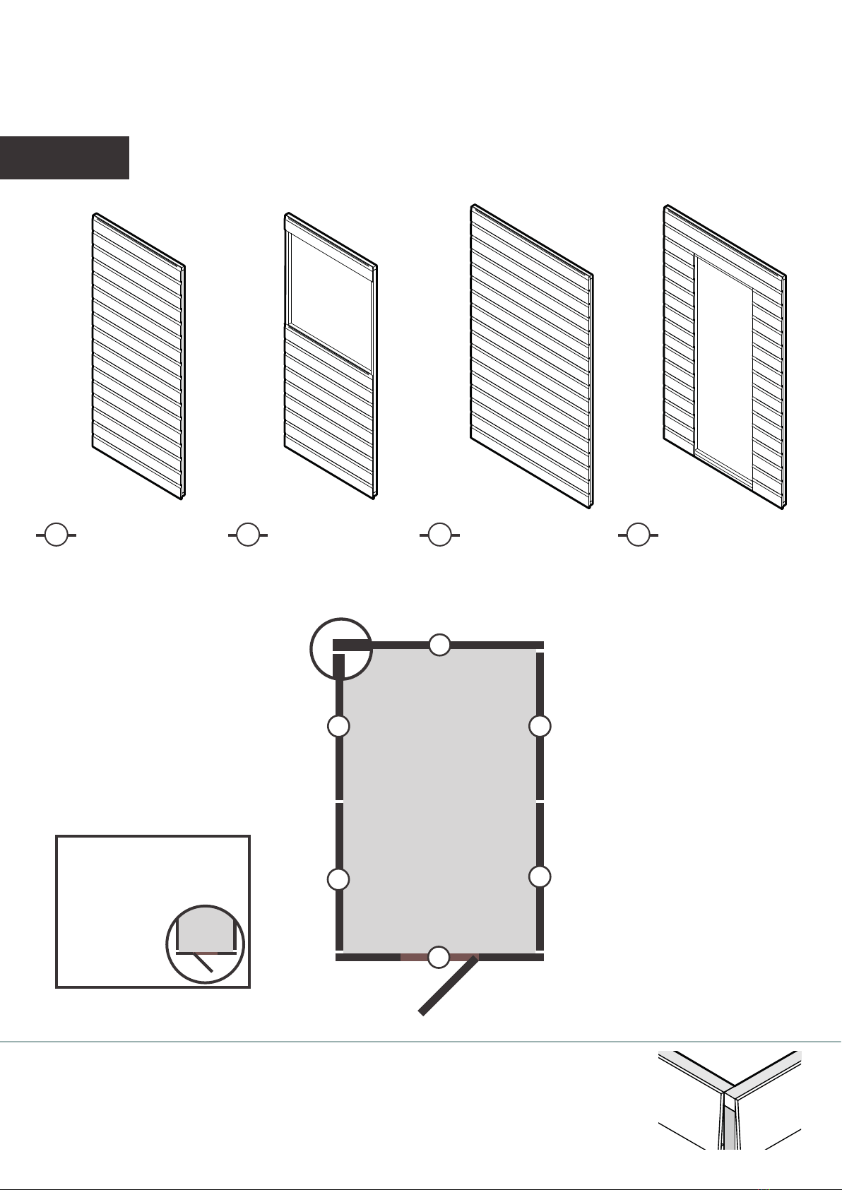
A3ft Panel (885 x 1945mm) C4ft Panel (1180 x 1945mm)
B3ft Panel (885 x 1945mm)
(Window)
KEY
PLEASE NOTE
The garden bar is made up of
multiple sections where same size
panels are interchangeable.
The door can be
hinged on either
side.
D4ft Panel (1180 x 1945mm)
(Door)
4
GARDEN BAR PANEL LAYOUT
Use the oor plan below, to identify the side panel positions before assemblying your garden bar.
Use the key and visuals below as a guide.
B
D
B
4’
6’ REVERSE APEX
C
A
A
Indicates the panel orientation
during construction.
PANEL POSITION
When assemblying your wall panels, ensure the timber framing on the panels are
ush at the corners. The space left next to the board is for the cover strip to sit into.
Ensure to apply the same panel position to all corners.
PRE-DRILL WITH
2-3MM BIT
FOR ALL STEPS
BELOW
PRE-DRILL WITH
2-3MM BIT
FOR ALL STEPS
BELOW.
PRE-DRILL WITH
2-3MM BIT
FOR ALL STEPS
BELOW.
50MM
SCREWS 50MM
SCREWS 50MM
SCREWS
50MM
SCREWS 50MM
SCREWS
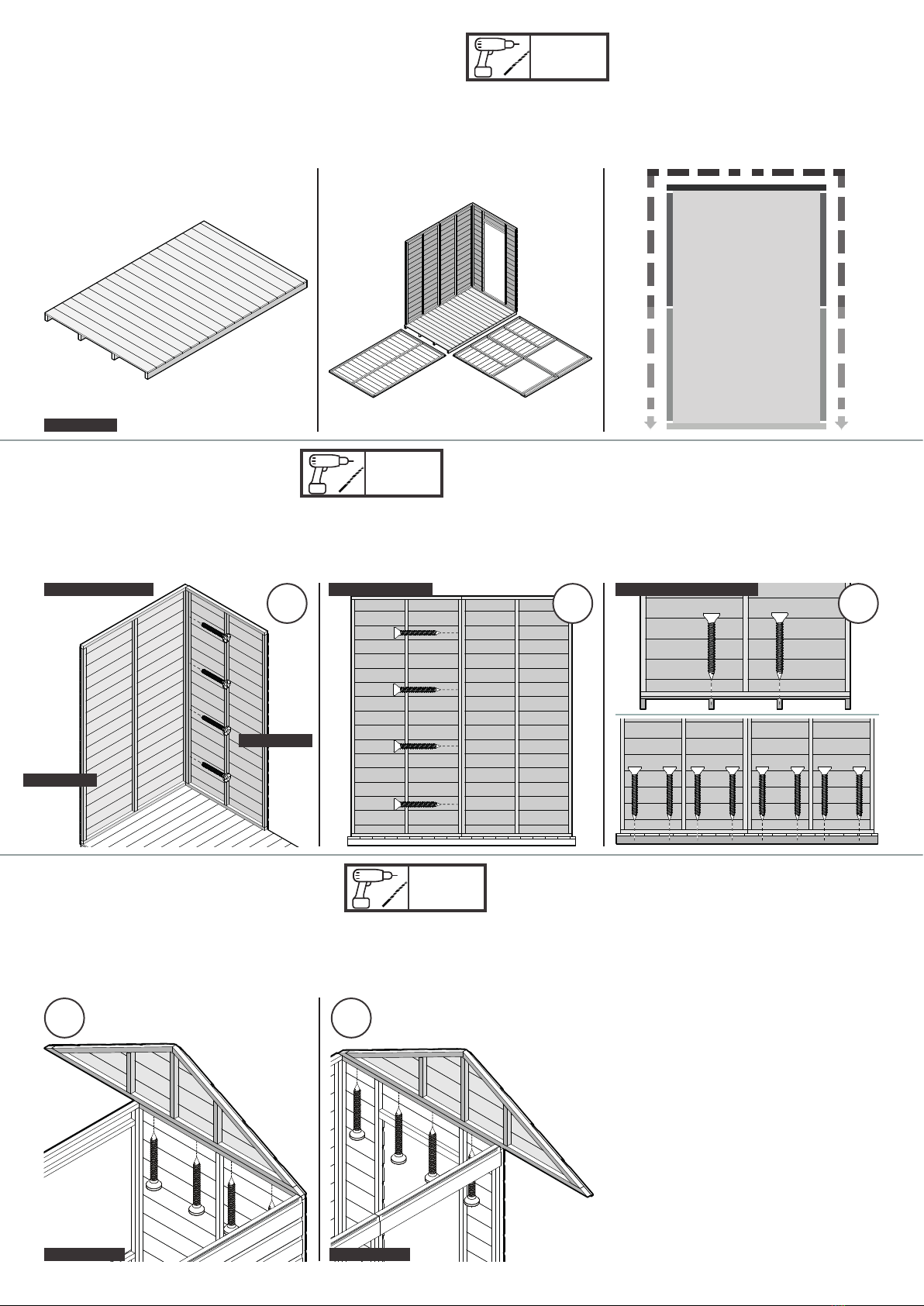
5
1a FLOOR & PANEL LAYOUT
1c APEX SECTIONS
1b SIDE PANELS
Position the Floor in your desired location. Lay out the panels around your garden bar
oor.
We recommend to start in a back corner,
then work from the back panels to the front
panels for assembly.
Attach the Apex Section by screwing to the
wall panels as shown below.
Repeat the process and attach the other
Apex Section by screwing to the wall panels as
shown below.
Start at a back corner. See the section layout
on page 4 to conrm position. Secure the
corner as shown below.
Repeat the process for the remaining panels
and secure the panels together. Ensure the
bottom board on the wall panel is up against
the oor’s outer edge.
Secure the panels into place by screwing into
the oor bearers beneath.
EG. INSIDE CORNER
SIDE PANEL
BACK PANEL
EG. BACK PANELS
APEX SECTION
EG. INTO FLOOR BEARERS
FLOOR
APEX SECTION
PRE-DRILL WITH
2-3MM BIT
FOR ALL STEPS
BELOW.
WALL
PANEL
FRAME
DOOR
WEATHER
STRIP
PRE-DRILL WITH
2-3MM BIT
FOR ALL STEPS
BELOW.
PRE-DRILL WITH
2-3MM BIT
FOR ALL STEPS
BELOW.
120MM
SCREWS
30MM
SCREWS 30MM
SCREWS
30MM
SCREWS
30MM
SCREWS
30MM
SCREWS
30MM
SCREWS
70MM
SCREWS
70MM
SCREWS
50MM
SCREWS 30MM
SCREWS 30MM
SCREWS
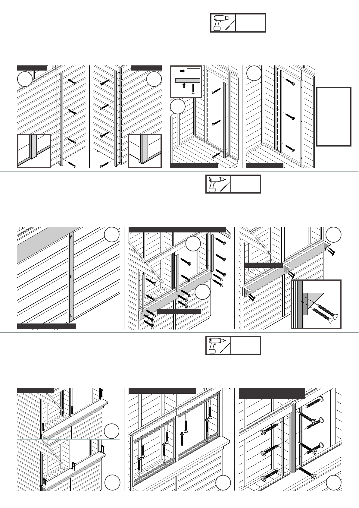
6
Secure the Door Weather
Strip to the side you want the
hinges, and ensure it’s ush to
the oor and against the face
of the wall panel framework.
Attach the Slamming Strip, to
the wall panel shown below.
This will be on the opposite
side you want the hinges.
PLEASE
NOTE
Screwing the
door weather
strip onto the
side panel
determines
the side of
your hinges.
2COVER STRIPS & DOOR STRIPS
Attach the Cover Strip to the
adjoining panels. Ensure it is
ush to the bottom edge of
the panels as shown below.
COVER STRIPS COVER STRIPS
DOOR WEATHER STRIP
3b TABLE & WINDOW ASSEMBLY
3a TABLE & WINDOW ASSEMBLY
Attach the Top Table Piece. Secure to the
Table Back Piece at each end and in the centre.
Then use 50mm screws to secure to the angled
braces.
Attach the Top and Bottom Window Strips.
Repeat this process for the other window
opening. Ensure the strips are ush to the
window opening.
First attach the Smaller Cover Strip to the
adjoining window panels as shown below. You
will need this to position your bar table for the
correct height.
Attach the Window Cover Strips with 30mm
screws. Position and ensure your Table Back
Piece is ush end to end and sitting on the
Smaller Cover Strip underneath. Fix with
70mm screws.
Attach the Angled Braces to the Table Back
Piece. Angle the screws to secure the braces
into place. Ensure the end Angled Braces are
ush to the edge and the other is central.
SLAMMING STRIP
Attach the Cover Strips to the
corners. Ensure they are ush
to the bottom edge of the
panels as shown below.
COVER STRIP (40 x 12 x 828)
TABLE BACK PIECE
COVER STRIPS (28 x 12 x 791) & (56 x 12 x 791)
ANGLED BRACE
TABLE TOP PIECE
Secure the two Window Opening Side Strips
as shown below. Attach the middle Window
Cover Strip.
WINDOW STRIPS (28 x 12 x 829) WINDOW STRIPS (28 x 12 x 765)
COVER STRIP (40 x 12 x 890)

28mm
223mm
55mm
223mm
461mm
PRE-DRILL WITH
2-3MM BIT
FOR ALL STEPS
BELOW
PRE-DRILL WITH
2-3MM BIT
FOR ALL STEPS
BELOW.
PRE-DRILL WITH
2-3MM BIT
FOR ALL STEPS
BELOW
25MM
SCREWS 25MM
SCREWS
25MM
SCREWS
30MM
SCREWS
30MM
SCREWS 30MM
SCREWS 30MM
SCREWS
7
4a ROOF OVERHANG
4b ROOF STRUCTURE
Attach a Z-bracket to each end of the Beam
as shown below. Repeat the process for all
Beams. The Beam should be ush to the
Z-bracket.
Position 3 x Beams to the Apex Sections, in
the overhang section using the measurements
below as a guide.
Secure the Beams to the Apex Sections from
underneath into the attached Z-Brackets.
Position the Beams on your roof and use
the measurement provided before securing in
place. Ensure you are measuring in between
the Beams as shown below.
Screw the Z-brackets to the Apex Sections to
secure the Beams as shown below.
Position the OSB sheet for the overhang.
Ensure the OSB is ush and ts in between the
Apex Sections as shown below. Secure the
OSB sheet to the Apex Sections.
Z-BRACKET
4c OSB ROOF SHEETS
Secure the OSB sheet to the Beams. Mark
out where the beams are positioned before
pre-drilling.
Attach a Roof Strip to your OSB Roof Sheet.
Ensure the Roof Strip is ush to the edge of
the sheet. Repeat for the other OSB Roof
Sheet.
Screw the OSB Roof Sheets into position
as shown below into the Apex Sections, wall
panels and Beams beneath.
BEAM
BEAM
OSB OVERHANG SHEET
(636 x 1826)
OSB ROOF SHEET
(1105 x 1858)
ROOF STRIP (28 x 28 x 1858)
BEAM
175mm
175mm 5mm
Allow a 5mm gap at the
top when tting the door.
DOOR FACE
NOTCH IN
LINE WITH
DOOR FACE
DOOR
Make sure the outer
face of the notch on
the hinge is in line
with the door face.
HINGE POSITION
100mm
100mm
PRE-DRILL WITH
2-3MM BIT
FOR ALL STEPS
BELOW
50mm
40MM
SCREWS
PRE-DRILL WITH
2-3MM BIT
FOR ALL STEPS
BELOW.
PRE-DRILL WITH
2-3MM BIT
FOR ALL STEPS
BELOW
25MM
SCREWS
25MM
SCREWS
25MM
SCREWS
25MM
SCREWS 25MM
SCREWS
25MM
SCREWS 25MM
SCREWS
8
4d FELT, FASCIAS & FINIALS
5a DOOR FIXINGS
Measure out 3 equal lengths and overlap
on the top, around the edges and fold the
corners; tack to keep secure. Ensure there is
a 50mm overhang, working from the bottom
to the top.
Secure the Fascias as shown below. Ensure to
screw the Fascias into the framework behind.
Secure the Finials as shown below. Ensure to
screw the Finials into the Fascias behind.
Attach 2 x hinges to the door frame using the
measurements provided. Please take note of
the hinge position shown below.
Place the Door into the opening, ensuring it
is level. Make sure the hinges are up against
the Door Weather Strip face. Secure the hinges
in place.
Fix the Padbolt as shown below. Ensure
the screws for the lock go into the Door’s
framework behind. Attach the receiver to the
panel’s framework.
5b SHUTTER FIXINGS
Attach 2 x hinges onto the Outside Shutter frame with the
measurements provided. Please take note of the hinge position shown
above. Secure the shutter to the window opening as shown below.
Ensure the shutter is positioned centrally. Repeat this process for the
other Outside Shutter.
Attach 2 x hinges onto the Inside
Shutter frame (with the lip) with the
measurements provided. Secure
the Inside Shutter to the Outside
Shutter. Ensure the shutter is
positioned centrally.
Position centrally and attach
the turn buttons, onto the Inside
Shutter frame. Ensure when the
buttons turn, they catch the side
window strips to hold the shutters
in place.
TOP TIP: Use a measuring tape to measure out
3 equal lengths & cut with a sharp knife. Hammer the
tacks into the felt. Add the tacks at 150mm intervals.
FASCIAS
FINIAL
DOOR
INSIDE SHUTTER INSIDE
SDP63GBARIS
WITH LIP
SDP63GBAROS
WITHOUT LIP
OUTSIDE SHUTTER

PRE-DRILL WITH
2-3MM BIT
FOR ALL STEPS
BELOW
25MM
SCREWS 25MM
SCREWS
Label Part Code
Description No.
AMSBFL46
Floor (1180x1826mm) 1
BSDM885TPP
Section A - 3ft Panel (885x1945mm) 2
CSDPGB885WP
Section B - 3ft Window Panel (885x1945mm) 2
DSDM1180TPP
Section C - 4ft Panel (1180x1945mm) 1
ESDM1180TDP
Section D - 4ft Door Panel (1180x1945mm) 1
FSDAMPEA6
6ft Apex Section (474x1828mm) 2
G40121925PDT
Cover Strip (40x12x1925mm) 5
H38121710PDT Door Weather Strip (38x12x1710mm) 1
I28121637PDT
Slamming Strip (28x12x1637mm) 1
J40120828PDT
Small Cover Strip (40x12x828mm) 1
K28120791PDT
Window Cover Strip (28x12x791mm) 2
L56120791PDT
Window Cover Strip (56x12x791mm) 1
M165401794PDT
Table Top & Back Pieces (165x40x1794mm) 2
N120400120PAI45DT
Angled Brace (120x40x120mm) 3
O28120829PDT
Window Opening Top & Bottom Strip (28x12x829mm) 4
P28120765PDT
Window Opening Side Strip (28x12x765mm) 2
Q40120890PDT
Window Cover Strip (40x12x890mm) 1
R45281770 Beam (45x28x1770mm) 7
SOSB18266368
OSB Overhang Sheet - (636x1826x8mm) 1
TOSB185811058
OSB Roof Sheet - (1105x1858x8mm) 2
U28281858 Roof Strip (28x28x1858mm) 2
V59121145PAII63DT
Fascia (59x12x1145mm) 4
WFIN20010512DTR
Finial (105x12x200mm) 2
XMSDDR
Door (582x1692mm) 1
YSDP63GBAROS
Outside Shutter Door - Without Lip (410x780mm) 2
ZSDP63GBARIS Inside Shutter Door - With Lip (410x780mm) 2
AA 1
6' x 4' Reverse Apex Garden Bar (SDA46GBAR)
Felt - Please contact our aftersales team with your product code if you are missing your felt.
9
Use the labelled components on the next page to help identify the part code and description.
5c SHUTTER & DOOR FIXINGS
Screw your hook to the Inside Shutter and
secure your receiver to the panel into the
framework behind. Repeat the process for
both sides.
Line up the hook and eye and mark the
edges with a pencil for guidance. Ensure the
hook and eye are level and secured to the
framework behind.
CHECK YOU HAVE ALL YOUR PARTS PRIOR TO ASSEMBLY.
(The parts do not have codes on them. They are listed below should you need to order one.)
Timber is a natural material of which will shrink and swell as a result of varying moisture content.
Assembly of damaged parts may be deemed to be acceptance and this may affect the remedies you are entitled to. If the product is not constructed
in accordance with the instructions, or is altered in anyway (e.g. painted), the manufacturer cannot be held liable for any resulting damage.
The components provided may be heavy. Please lift with caution and with a minimum of 2 people.
Fix a Turn Button to the top and bottom
of the door panel. Ensure to screw into the
framework behind and once turned, the Door
is held in place.

10
H I J K L M N O P Q R
S T U V W X Y Z AA
A B C D E
F G
CHECK AND TIGHTEN ALL THE FIXINGS APPLIED TO THIS PRODUCT ON A REGULAR BASIS.
Table of contents
Other Forest Lawn And Garden Equipment manuals

Forest
Forest SCP90 User manual

Forest
Forest SBP43M User manual

Forest
Forest HANBURY DOMED TOP ARCH User manual

Forest
Forest SLATWALLPLANT1 User manual

Forest
Forest CALEDONIAN CALBASEPK2 User manual

Forest
Forest POTATO PLANTER User manual

Forest
Forest 2.4M ULTIMA PERGOLA Manual

Forest
Forest OVERLAP APEX LOG STORE User manual


