Page 3 / 4
Ce Guide peut faire l’objet de changement sans préavis. www.ifar.ca pour la récente version.
This Guide may change without notice. www.ifar.ca for latest version.
3
PROCÉDURE DE
PROGRAMMATION
PROGRAMMING
PROCEDURE
Follow the programming procedure
on page 4. Suivez la procédure de programmation à
la page 4.
Déterminez si le démarreur
à distance ou système
d'alarme est compatible en
Data-Link 2-voies.
Determine if the remote-
starter or alarm system
supports 2-way Data-Link.
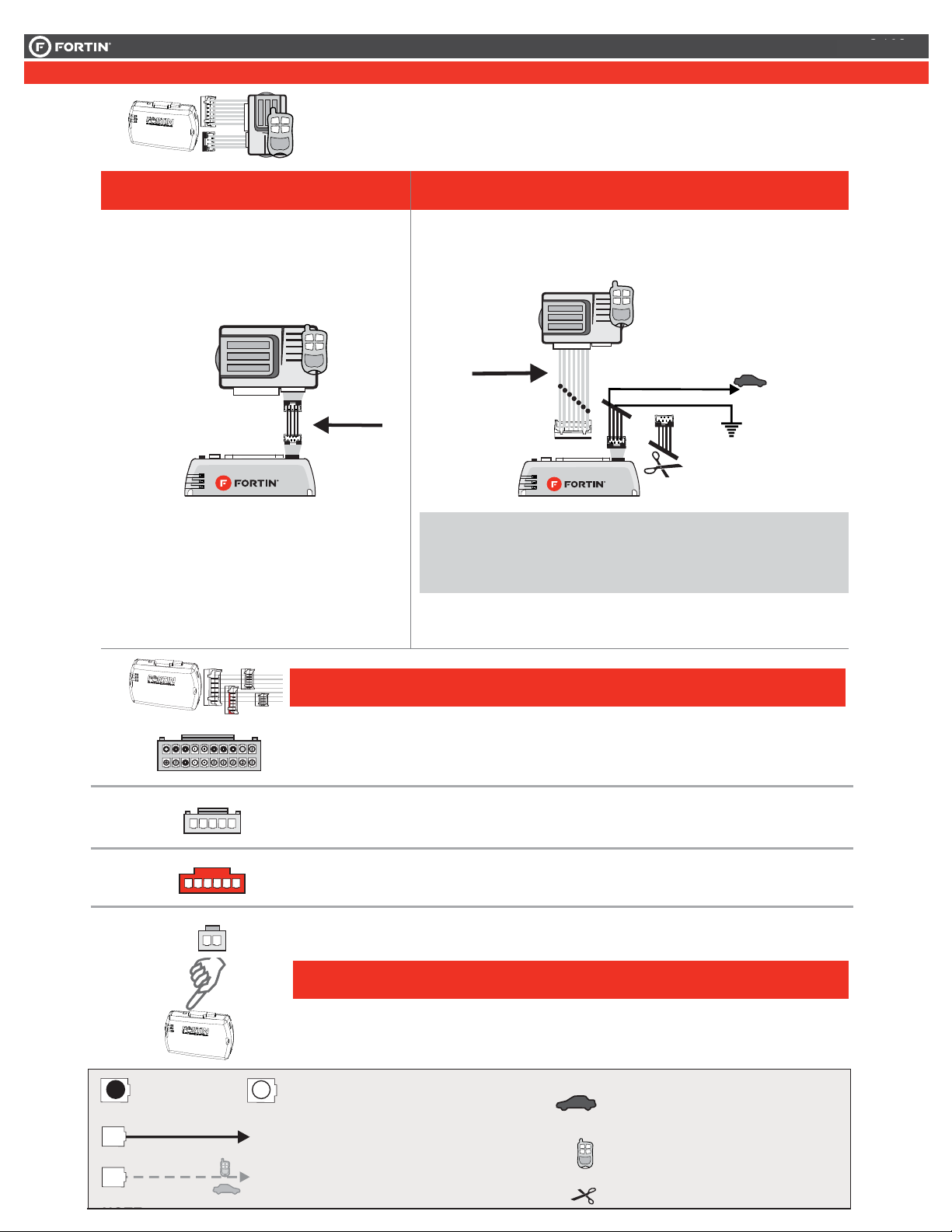
Faire les branchements :Make the connections :
Remote
Starter/Alarm
Démarreur à
distance/alarme
4 Pin
WITH DATA-LINK
AVEC DATA-LlNK
In order to use this type of connection the
remote-starter or alarm-system must be
compatible with the Fortin Data-link
protocol. Consult the installation guide or
visit www.fortinbypass.com/datalink/ for more
information.
Red | Rouge +12V
Black | Noir Ground
20 Pin Conn. 4 Pin
For all other remote-starters or
alarm-systems perform the
following connections.
WITH OUT DATA-LINK
SANS DATA-LlNK
Cut off one plug of the 4 Pin
Data-Link connector
Connect the Red wire to +12V
Connect the Black wire to
Ground
1
2
3
Coupez l'extrémité du connecteur
4 pins Data-Link
Connectez le fil rouge au 12V
Connectez le fil noir à la masse
du véhicule.
1
2
3
Remote
Starter/Alarm
Démarreur à
distance/alarme
20 Pins Connecteur (Blanc ):
Effectuez les branchements associés au
véhicule dans le GUIDE DES VÉHICULES.
20 Pin Connector (White):
Make the connections associated with
the vehicle from the VEHICLE FIT
GUIDE.
5 Pins Connecteur CAN (Blanc):
Effectuez les branchements.(Si nécessaire)
5 Pin Connector CAN (White):
Make the connections (if required)
6 Pins Connecteur RELAI (Rouge):
Effectuez les branchements.(Si nécessaire)
6 Pin Connector RELAY (Red):
Make the connections (if required)
2 Pins Connecteur (Blanc):
Effectuez les branchements.(Si nécessaire)
2 Pin Connector (White):
Make the connections (if required)
5 Pin
onn
6 PIN
NN.
2 Pin
onn
Le démarreur à distance ou le système
d'alarme doit être compatible avec le
protocole Data-link Fortin pour ces
branchements. Consultez le guide
d'installation du démarreur à distance ou du
système d'alarme ou visitez le
www.fortinbypass.com/datalink/ pour plus
d'informations.
Pour tout autres types de
démarreurs à distance ou
d'alarme, effectuez les
branchements suivants.
20 Pin
onn
3
PROCÉDURE DE
PROGRAMMATION
PROGRAMMING
PROCEDURE
Follow the programming procedure
on page 4. Suivez la procédure de programmation à
la page 4.
Faire les branchements :Make the connections :
20 Pins Connecteur (Blanc ):
Effectuez les branchements associés au
véhicule dans le GUIDE DES VÉHICULES.
20 Pin Connector (White):
Make the connections associated with
the vehicle from the VEHICLE FIT
GUIDE.
5 Pins Connecteur CAN (Blanc):
Effectuez les branchements.(Si nécessaire)
5 Pin Connector CAN (White):
Make the connections (if required)
6 Pins Connecteur RELAI (Rouge):
Effectuez les branchements.(Si nécessaire)
6 Pin Connector RELAY (Red):
Make the connections (if required)
2 Pins Connecteur (Blanc):
Effectuez les branchements.(Si nécessaire)
2 Pin Connector (White):
Make the connections (if required)
5 Pin
onn
6 PIN
NN.
2 Pin
onn
20 Pin
onn
3
PROCÉDURE DE
PROGRAMMATION
PROGRAMMING
PROCEDURE
Follow the programming procedure
on page 4. Suivez la procédure de programmation à
la page 4.
INSTALLATION PROCEDURE | PROCÉDURE D’INSTALLATION
Connect to vehicle
Branchement au véhicule
Connect to Remote-Starter/Alarm
Branchement au démarreur
à distance/Alarme
Connection not required with Data-link
Branchement non requis avec Data-Link
Input | Entrée Output | Sortie
Connection always required
Branchement toujours requis
Cut | Couper
Page 3 / 18Page 3 / 22


