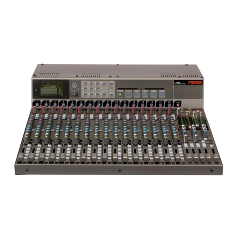
Fostex 450 User manual

Owner’s
Manual
Model
RECORDING
MIXER
OO
90
09
90
90
OO
90
99
09
90
OO
OO
OO
OO
OO
OO
FOStGX

PAGE
TABLE
OF
CONTENTS
SECTION
1
Feature
Descriptions
2
SECTION
2
Introduction
4
SECTION
3
Interconnections
&
Installation
'
4
SECTION
4
External
Effects
&
Processing
5
SECTION
5
Using
the
Parametric
Equalizer
6
SECTION
6
Multitrack
Applications
7
SECTION
7
P.A.
Applications
10
SECTION
8
Maintenance
12
SECTION
9
Block
Diagram
13
SECTION
10
Specifications
14
SECTION
11
Bibliography
14
Safety
Instructions
WARNING:
To
avoid
possible
electric
shock
hazard,
do
not
expose
this
appliance
to
rain
or
moisture.
There
are
no
user-serviceable
parts
inside.
Refer
servicing
to
qualified
service
personnel.
HOUSEHOLD
USE
ONLY


SECTION
1
FEATURE
DESCRIPTIONS
1.
INPUT
LEVEL
TRIM
CONTROL
[TRIM]
When
the
Input
Selector
is
set
to
INPUT,
the
preamplifier
gain
can
be
continuously
controlled
from
10dB
through
50dB.
At
full-
CW
of
the
knob,
the
gain
is
50dB
which
matches
a
—60dBV
(ImV)
mic
input
level
at
the
XLR
jack
or
the
phone
jack
of
the
rear
panel.
At
full
CCW
of
the
knob,
the
gain
is
10dB
which
matches
a
—20dBV
(0.1
V)
level
from
an
electronic
musical
instrument
and
signal
processor.
When
the
Input
Selector
is
set
to
TAPE,
tape
input
signals
from
the
TAPE
IN
phono
jack
of
the
patch
panel
cannot
be
controlled
by
this
trim
control.
2.
INPUT
SELECTOR
[INPUT
LINE/MIC,
OFF,
TAPE]
A
3-position
switch
for
selecting
signals
applied
to
the
input
jacks
of
each
channel.
The
center,
OFF
position,
in
a
con¬
venient
way
to
mute
the
input
signal.
‘LINE/MIC:
In
this
position,
signals
from
mic
level
through
line
level
applied
to
the
rear
panel
INPUT
XLR
or
phone
jack
feed
the
preamplifier
and
are
applied
to
the
input
fader.
‘OFF:
Signals
to
the
input
fader
are
bypassed
in
this
position.
‘TAPE:
The
recorder/reproducer
output
bypasses
the
preamplifier
and
is
applied
to
the
input
fader
in
this
position
of
the
switch.
Not
only
can
this
input
position
be
used
to
mixdown
a
multitrack
recorder
output,
but
it
can
also
be
used
to
receive
the
output
from
an
external
signal
processor.
3.
AUX
1
INPUT
LEVEL
CONTROL
[AUX
1]
This
control
feeds
the
input
channels’
post-fader
post-equalizer
signals
to
a
summing
amplifier
that
mixes
the
AUX
1
signals
of
all
eight
input
channels
for
the
AUX
1
jack.
This
mono
mix
may
be
used
to
feed
external
signal
processing
equipment.
4.
INPUT
SELECTOR
FOR
AUX
2
OUTPUT
[AUX
2]
Input
signals
to
be
sent
to
the
AUX
2
buss
out
are
selected
by
this
3
position
switch.
*PRE:
In
this
position,
the
input
signal
is
pre-fader
and
pre¬
equalizer.
‘POST:
In
this
position,
the
input
signal
is
post
fader
and
post-
equalizer.
‘TAPE:
The
output
of
the
recorder
is
the
input
signal
at
this
position.
5.
GAIN
POT
FOR
AUX
2
BUSS
OUT
[GAIN]
Gain
pot
for
adjusting
the
level
of
the
signal
selected
by
switch
4),
above.
6.
PAN
POT
FOR
AUX
2
BUSS
OUT
[PAN]
A
2-channel
PAN
pot.
With
the
12
o’clock
knob
position
as
center,
CCW
rotation
will
increase
the
left
channel
level
of
the
2-channel
buss
out
and
decrease
the
right
channel
level
at
the
same
time
(vice-versa
for
CW
rotation).
7.
4-CHANNEL
BUSS
OUT
SELECTOR
[ASSIGN]
In
combination
with
the
PAN
pot
located
directly
under
this
selector,
it
assigns
the
input
signal
to
the
4-channel
buss
out.
‘1
-2:
In
this
selector
position,
the
PAN
pot
can
control
only
the
signals
between
CHAN
1
and
CHAN
2
of
the
,
4-channel
buss
out.
‘OFF:
In
this
position,
signals
from
the
input
section
to
the
4-channel
buss
out
are
switched
off.
For
example,
if
you
were
mixing
the
4-channel
buss
out
with
the
output
of
an
echo
or
reverberation
unit
by
using
the
4-channel
buss
input,
and
you
wanted
to
monitor
echo
or
reverberation
return
only,
turn
this
switch
OFF.
‘3-4:
In
this
selector
position,
the
PAN
pot
can
control
only
the
signals
between
CHAN
3
and
CHAN
4
of
the
4-channel
buss
out.
8.
PAN
POT
FOR
4-CHANNEL
BUSS
OUT
[PAN]
The
signals
selected
by
the
4-channel
buss
out
selector
of
7),
above,
can
be
pan
controlled
by
this
pot
for
CHAN
1
only,
CHAN
1
and
2,
or
CHAN
2
only
(CHAN
3
only,
CHAN
3
and
4,
or
CHAN
4
only).
The
12
o'clock
position
of
the
PAN
pot
is
center.
If
it
is
rotated
CCW,
the
signal
applied
to
CHAN
1
(or
CHAN
3)
increases
and
that
to
CHAN
2
(or
CHAN
4)
decreases
(vice-versa
for
CW
rotation).
9.
PARAMETRIC
EQUALIZER
[EQ]
A
2-band
parametric
equalizer
for
60Hz
~
1kHz
and
400Hz
~
6kHz,
and
a
shelving
type
equalizer
for
10kHz.
Boost
and
cut
levels
are
±15dB
(max).
10.
INPUT
SOLO
BUTTON
[SOLO]
When
the
SOLO
button
of
any
channel
is
depressed,
the
headphone
output
and
monitor
output
normally
present
changes
to
post
fader
and
equalizer
input.
The
SOLO
buttons
are
lock
type
switches.
The
SOLO
functions
are
for
MON
OUT
and
PHONE
OUT
and
do
not
affect
the
4-channel
buss
out.
11.
OVERLOAD/SOLO
INDICATOR
Indicates
the
input
solo
mode
when
the
SOLO
button
is
depressed
or
when
this
button
is
released,
overload
at
the
preamplifier
output.
12.
INPUT
FADER
The
optimum
level,
relative
to
noise
and
distortion,
is
obtained
when
the
input
fader
knob
is
set
at
OdB.
Therefore,
it
is
advisable
to
first
set
the
input
fader
at
this
point
and
then
set
the
overall
level
by
the
input
trim
control.
13.
4-CHANNEL
BUSS
OUT
SOLO
BUTTON
[SOLO]
The
4-channel
buss
out
signals
for
each
channel
can
be
monitored
individually
via
the
pre-fader.
Using
the
same
logic
as
input
solo,
monitor
signals
at
MON
OUT
and
PHONES
are
changed
to
4-channel
buss
out
signals.
14.
4-CHANNEL
BUSS
INPUT
LEVEL
CONTROL
[BUSS
INPUT]
For
individual
level
control
of
each
channel.
Effects
return
signals
applied
to
the
4-channel
BUSS
IN
jacks
on
the
patch
panel
or
signals
from
another
mixer
are
controlled
here.
15.
PAN
POT
FOR
STEREO
MASTER
OUTPUT
[BUSS
PAN]
This
pan
pot
has
the
function
of
mixing
the
4-channel
buss
out
signals
with
the
stereo
master
output.
16.
MONITOR
SELECT
BUTTONS
With
these
buttons,
either
channel
1,2,3
or
4
of
the
4-channel
buss
out,
output
of
AUX
1,
or
output
of
channel
L/R
of
AUX
2
buss
out
can
be
selected
and
applied
to
PHONES
and
MONITOR
OUT.
Seven
push
buttons
for
channels
1,2,3,4
AUX
1
and
AUX
2
2

L/R
can
be
divided
into
four
groups
—
channels
1
and
2,
3
and
4,
AUX
1
and
AUX
2
L/R.
By
pressing
the
1
and
2
buttons
together,
the
signal
from
channel
1
is
applied
to
the
left
channel
of
PHONES
and
MONITOR
OUT,
and
the
signal
from
channel
2
is
applied
to
the
right
channel.
Press
either
1
or
2,
and
the
signal
selected
can
be
applied
to
both
the
left
and
right
channels.
The
3
and
4
group
functions
in
the
same
way
as
group
1
and
2.
When
the
AUX
1
button
is
depressed,
the
AUX
1
signal
is
applied
to
both
PHONES
and
MONITOR
OUT.
The
group
function
of
the
AUX
2
button
is
the
same
as
for
BUSS
1
and
2
or
BUSS
3
and
4.
When
the
four
button
groups
(BUSS
1
and
2,
BUSS
3
and
4,
AUX
1,
and
AUX
2)
are
simultaneously
depressed,
these
signals
will
be
mixed
and
applied
to
PHONES
and
MONITOR
OUT.
17.
METER
SELECT
SWITCH
[METER]
Chooses
the
four
LED
bargraph
meter
display
for
4-channel
buss
out
signals
or
the
stereo
master
outputs.
When
set
for
stereo
master
out,
the
two
LED
bargraph
meters
at
the
right
side
will
not
function.
18.
SOLO
LEVEL
CONTROL
[SOLO]
This
is
the
knob
to
control
monitor
level
of
the
input
channel
solo
and
4-channel
buss
out
solo
signal.
As
monitor
levels
are
normally
set
first
(see
the
following
items
19)
and
20),
solo
level
is
generally
set
second.
19.
MONITOR
LEVEL
CONTROL
[MONITOR]
This
pot
controls
the
monitor
output
level.
20.
HEADPHONE
LEVEL
CONTROL
[PHONES]
21.
STEREO
MASTER
OUTPUT
LEVEL
CONTROL
[STEREO
MASTER]
The
master
level
control
of
the
4-channel
buss
output
signal
mixed
down
to
stereo.
22.
4-CHANNEL
BUSS
MASTER
FADER
23.
HEADPHONE
JACK
[PHONES]
These
two
jacks
are
wired
in
parallel.
24.
LED
BARGRAPH
METERS
These
display
levels
of
the
4-channel
buss
output
or
stereo
master
output.
25.
SOLO
INDICATOR
[SOLO]
This
LED
is
lit
when
either
the
input
channel
solo
or
4-channel
buss
out
solo
button
is
depressed.
26.
POWER
INDICATOR
[POWER]
27.
POWER
SWITCH
[POWER]
28.
PHANTOM
POWER
SWITCH
[PHANTOM]
Phantom
power
supply
voltage
is
48V
DC.
30.
TAPE
IN
JACK
[TAPE
IN]
Input
jacks
for
receiving
(normally)
the
outputs
from
a
multi¬
track
recorder.
In
addition,
these
jacks
can
be
used
to
connect
outputs
from
reverberation
units,
compressor/limiters
and
other
line
level
sources.
31.
ACCESSORY
SEND/RECEIVE
JACK
[ACC
SEND
RCV]
This
is
the
patch
point,
between
the
preamplifier
output
and
the
input
fader,
where
a
signal
processor,
such
as
an
equalizer,
is
plugged
in.
'
32.
PHONE
JACK
INPUTS
[INPUT]
These
input
jacks
are
for
unbalanced
inputs
from
mic
level
to
line
level:
from
—60dBV
(ImV)
through
—20dBV
(0.1V).
Input
impedance
is
about
50K
ohms.
33.
XLR
JACK
INPUTS
[INPUT]
These
jacks
are
for
balanced
mic
input
signals
and
will
handle
levels
of
-60dBV
(ImV)
through
—20dBV
(0.1V).
Unbalanced
signals
can
also
be
handled
by
these
XLR
jacks:
pins
#1
and
#2
will
be
GND;
PHANTOM
must
be
switched
OFF.
34.
4-CHANNEL
BUSS
IN
[4
CHAN
BUSS
IN]
Input
jacks
for
mixing
the
outputs
from
an
external
processor
into
the
4-channel
buss
line.
35.
4-CHANNEL
BUSS
OUT
[4
CHAN
BUSS
OUT]
Normally,
these
jacks
will
feed
a
multitrack
recorder.
36.
AUX
2
BUSS
IN
[AUX
2
IN]
Input
jacks
for
mixing
the
outputs
from
an
external
processor
into
the
AUX
2
buss
line.
37.
AUX
2
BUSS
OUT
[AUX
2
OUT]
The
AUX
2
buss
output
jacks
are
for
a
monitor
amplifier,
master
recorder,
etc.
38.
AUX
1
BUSS
IN
[AUX
1
IN]
Input
jacks
for
mixing
the
outputs
from
an
external
processor
into
the
AUX
1
buss
line.
39.
AUX
1
BUSS
OUT
[AUX
1
OUT]
The
AUX
1
buss
output
jacks
are
for
signal
processors,
slap
echo
recorders,
etc.
40.
MONITOR
OUTPUT
[MON
OUT]
The
4-channel
buss
out,
the
AUX
1
buss
out
or
the
AUX
2
buss
out,
as
selected
by
the
MONITOR
select
switch,
is
active
here.
These
outputs
are
generally
connected
to
the
cue
and
monitor
amplifiers.
41.
STEREO
MASTER
OUTPUT
[STEREO
MASTER]
The
4-channel
buss
out
after
mixdown
to
stereo
is
the
output
here,
and
it
is
generally
applied
to
the
2-channel
master
recorder.
42.
AC
POWER
CORD
29.
D
IRECT
OUT
JACK
[D.
OUT]
This
output
stage
is
immediately
after
the
input
fader
and
parametric
equalizer.
3

SECTION
2
INTRODUCTION
The
Fostex
Model
450
is
one
of
the
most
flexible,
versatile
mixers
ever
designed
for
its
price
category.
With
a
complement
of
features
such
as
phantom
power,
in-line
monitoring,
input
solo
and
multiple
send/receive
circuits
and
patch
points,
this
8x8x4x2
mixer
can
be
used
in
a
wide
variety
of
creative
applications.
From
multitrack
recording
to
complex
sound
reinforcement,
the
450
delivers
quality
audio,
direct
or
through
the
summing
amplifiers,
pre-
or
post-
EQ
and
fader.
Anywhere
you
need
it;
however
you
want
it
to
sound.
Fostex’s
engineers,
who
pioneered
the
development
of
personal
multitrack
and
mixing
equipment,
designed
the
450
to
meet
the
needs
of
the
serious
small
studio
or
production
facility
as
well
as
stage
and
P.A.
users.
It
combines
ease
of
operation,
reliability
and
flexibility
in
an
extremely
compact
package,
and
is
particularly
compatible
with
multitrack
equipment
such
as
the
Fostex
8-track,
1
/4"
recorder
Model
80.
Your
450
should
provide
years
of
top
audio
performance
with
a
minimum
of
service,
using
reasonable
care.
HOW
TO
USE
THIS
MANUAL
While
it
may
be
possible
to
"get
by”
without
reading
this
manual,
the
utmost
in
creative
results
can
only
be
obtained
when
one
is
thoroughly
acquainted
with
the
450
and
its
full
capabilities.
We
suggest
quickly
reading
this
manual
once
before
using
the
450,
then
re-reading
the
manual
later,
after
becoming
familiar
with
the
basic
functions
of
the
mixer.
Section
1
contains
brief
descriptions
of
each
feature
and
control.
This
is
handy
for
quick
references,
although
for
a
more
detailed
step-by-step
guide
to
connection
and
use,
consult
Section
3.
The
remainder
of
the
manual
will
illustrate
in
more
detail,
the
use
of
external
processing
equipment,
the
equalizers,
and
examples
of
mixing
for
multitrack,
production,
and
P.A.
Then,
most
important,
study
and
refer
to
the
block
diagram
in
Section
10.
You
will
find
this
to
be
an
important
aid
when
reading
the
use
and
applications
sections
of
this
manual,
as
well
as
providing
you
with
more
specific
knowledge
of
the
450
and
its
remarkable
potential.
SECTION
3
INTERCONNECTIONS
AND
INSTALLATION
Whatever
the
application,
certain
standard
procedures
should
be
followed
in
setting
up
the
mixer
for
use.
The
power
cord
of
the
mixer
should
be
connected
to
an
AC
supply
of
the
correct
voltage.
While
the
output
of
the
Model
450
incorporate
a
circuit
to
prevent
an
audible
power
on
“thump”,
it
is
always
advisable
to
turn
the
power
on
to
amplifiers
or
tape
recorders
connected
to
the
outputs
of
the
mixer
AFTER
the
mixer
has
been
switched
on.
CONNECTING
THE
INPUTS
The
input
circuits
of
the
Model
450
are
such
that
they
may
accommodate
an
extremely
wide
range
of
input
signals.
You
may
connect
virtually
any
signal,
ranging
from
microphones
to
electric
musical
instruments
level,
directly
to
the
input
jack.
Each
balanced
XLR
mic
input
has
a
phantom
power
switch
for
use
with
certain
condenser
microphones.
NOTE:
Never
connect
any
signal
output
rated
in
“Watts”
to
any
input
of
the
Model
450.
These
are
often
high
voltage
signals
ordinarily
intended
for
loudspeakers.
If
you
need
to
make
such
a
connection
use
a
“Direct
Injection”
or
“DF’box,
or
direct
box
obtainable
from
your
dealer.
Failure
to
do
this
may
result
in
damage
to
the
circuits
of
the
Model
450,
and/or
the
power
amplifier.
To
set
the
input
trim,
adjust
this
control
on
maximum
signal
peaks
until
the
LED
above
the
corresponding
faderjustceases
to
flash.
This
will
be
the
optimum
input
level.
Should
the
signal
level
rise,
the
LED
will
start
to
flash
again,
giving
you
clear
indication
that
you
should
reduce
the
setting
of
the
trim
control
again.
"Tape
in”
(18)
and
"buss
in"
(21),
accept
a
-lOdBV
(0.3V)
level.
This
is
compatible
with
all
Fostex
recording
equipment
and
most
other
musicians’
studio
equipment.
These
inputs
will
also
accept
a
nominal
level
of
OdBm,
which
are
standards
in
many
professional
studios,
though
the
overload
headroom
will
be
somewhat
lower.
Remember,
as
long
as
your
input
LED
is
not
flashing,
you
are
not
overloading
any
of
the
input
amplifiers.
If
required
you
can
include
a
simple
input
attenuator
in
line
with
your
input
signal.
If
in
doubt
consult
your
dealer.
CONNECTING
THE
OUTPUTS
All
outputs
are
at
a
nominal
—lOdBV
(0.3V)
level.
This
signal
level
is
compatible
with
all
Fostex
recording
equipment
and
most
other
musician’s
studio
equipment.
While
you
may
find
that
certain
recorders,
amplifiers
or
signal
processors
are
specified
with
a
nominal
"OdBm"
or
“OdBV”
level,
these
often
have
a
front
panel
input
control
or
pre-set
which
will
readily
accommodate
this
—
lOdBV
level.
It
is
important
to
set
the
input
level
control
on
equipment
connected
to
the
mixer
outputs,
to
an
optimum
setting
to
achieve
the
best
minimum
noise,
and
maximum
overload
performance.
Setting
correct
levels
is
a
prime
factor
in
attaining
the
maximum
dynamic
range
performance
from
any
professional
audio
system.
While
presetting
inputs
to
external
equipment
need
only
be
done
once,
individual
input
channel
levels
must
be
trimmed
when
mixing
various
sources
via
various
microphones.
4

section
4
EXTERNAL
EFFECTS
AND
PROCESSING
The
nearest
thing
in
real
life
to
what
is
commonly
termed
echo,
is
the
effect
of
the
repeats
which
you
hear
when
you
shout
in
the
midst
of
a
mountain
range.
In
the
studio
this
can
be
achieved
by
feeding
the
output
of
the
play
head
of
a
tape
recorder
or
special
tape
loop
deck
back
to
the
record
heads.
Many
electronic
devices
using
digital
electronics
are
available,
and
these
do
much
the
same
job.
This
effect
is
normally
reserved
as
a
special
effect
only,
and
should
not
be
confused
with
reverberation.
The
sound
of
reverb
is
similar
to
that
of
a
large
empty
concert
hall.
Reflections
of
the
original
sound
are
so
close
and
diffuse,
that
no
distinct
repeats
are
heard.
This
effect
is
often
simulated
by
devices
employing
a
large
metal
plate
or
torsionally
driven
coiled
springs.
The
effect
is
normally
used
to
fill
out
the
sound
of
a
vocal
or
instrument
which
has
been
closed-miked,
or
is
otherwise
void
of
natural
reverbera¬
tion.
Added
judiciously
it
will
provide
commercial
fullness
and
body
to
a
recording.
Used
excessively
it
can
create
exaggerated
illusions
of
space
and
loss
of
clarity
and
intelligibility.
The
echo
or
reverb
effect
is
proportionately
added
to
the
direct
signal
passing
through
the
mixer.
The
following
describes
how
to
connect
either
an
echo
or
reverb,
or
in
fact
any
other
effect
such
as
a
phaser,
flanger,
doubler,
etc.,
to
the
Model
450
signal
path.
Figure
4-2.
There
are
two
ways
to
patch
a
single
channel
processor,
post-fader,
post-EQ.
(A).
Aux
1
out
to
processor
to
Buss
in;
(B)
direct
out
to
processor
to
buss
in
Figure
4-1.
A
single
channel
processor
is
patched
to
an
input
channel,
pre-fader,
pre-EQ.
-iCdBv
NOTE:
This
method
of
connecting
the
effector
(Noise
gate,
limiter/compressor,
chorus
unit,
etc.)
is
very
effective
when
directly
processing
the
original
sound.
<B)
(A)
NOTE:
This
method
of
connecting
the
effector
(Digital
delay,
reverberation,
etc.)
is
very
effective
when
adding
the
processed
sound
to
the
original
sound.
5

Figure
4-3.
A
stereo
processor
is
patched
to
the
Aux
2
buss
with
your
choice
of
pre-
or
post-EQ
and
fader
SECTION
5
USING
THE
PARAMETRIC
EQUALIZER
The
Model
450
incorporates
one
fixed
and
two
band
parametric
type
equalizers
which
have
considerable
advantage
in
fine-tuning.
When
equalizing
individual
instruments
it
is
preferable
to
emphasize
a
narrow
band
around
a
preselected
frequency.
While
a
graphic
equalizer
or
switched
frequency
may
provide
a
greater
selection
of
frequencies,
the
parametric
design
permits
you
to
find
the
fundamental
tonal
qualities
of
instruments
of
those
frequency
bands
which
give
you
the
maximum
control
over
the
sound.
In
PA
applications,
you
will
find
that
you
can
tune
out
acoustic
feedback
or
ringing,
or
correct
a
gross
house
resonance.
IMPORTANT:
Before
using
any
equalizer,
always
try
to
achieve
the
sound
that
you
want
by
moving
the
position
of
the
microphone
or
changing
the
microphone
type.
Learn
to
use
good
microphone
techniques
before
applying
electronic
tone
correction.
TYPICAL
EQUALIZATION
RESPONSE
GRAPH
INSTRUMENT
CUTTING
BOOSTING
OTHER
COMMENTS
Human
Voice
Scratchy
at
2kHz
Nasal
at
1kHz
Popping
p's
below
80Hz.
Hot
at
8
or
12kHz
Clarity
above
3kHz
Body
at
200—400Hz
Tend
towards
thin
when
blending
many
voices
Piano
Tinny
at
1—2kHz
Boomy
at
320Hz
Presence
at
5kHz
Bass
at
125Hz
Not
too
much
bass
when
mixing
with
rhythm
section
Electric
Guitar
Muddy
below
80Hz
Clarity
at
3.2kHz
Bass
at
125Hz
Acoustic
Guitar
Tinny
at
2-3.2kHz
Boomy
at
200Hz
Sparkle
above
5kHz
Full
at
125Hz
Electric
Bass
Tinny
at
1kHz
Boomy
at
125Hz
Growl
at
620Hz
Bass
below
80Hz
Sound
varies
greatly
with
strings
used
String
Bass
Hollow
at
620Hz
Boomy
at
200Hz
Slap
at
3.2—5kHz
Bass
below
200Hz
Snare
Drum
Annoying
at
1
kHz
Crisp
above
2kHz
Full
at
125Hz
Deep
at
80Hz
Also
try
adjusting
tightness
of
snare
wires
Bass
Drum
Floppy
at
620Hz
Boomy
below
80Hz
Slap
at
3.2—5kHz
Bass
at
80—125Hz
Usually
record
with
front
drum
head
off
Put
blanket
inside
of
drum
resting
against
the
head.
6

section
6
MULTITRACK
APPLICATIONS
Multitrack
recording
is
generally
considered
to
be
the
process
of
recording
a
performance
in
sequence,
building
tracks
one
or
more
at
a
time,
then
reviewing,
changing,
and
adding
new
ideas,
until
each
part
is
idealized.
A
single
performer
can
thus
create
an
entity
not
possible
in
real
time,
or
individuals
in
a
group
may
perform
as
many
(or
few)
“takes”
as
necessary
without
imposing
on
the
others.
When
all
tracks
have
been
satisfactorily
recorded,
one
can
take
whatever
time
is
required
to
combine
them
into
an
artistic
composite
in
the
"mixdown”
process.
Even
at
this
point,
flexibilities
are
available
to
change
the
sound
or
character
of
the
separate
tracks
by
means
of
electronic
effects.
Further,
a
performer
not
available
at
the
initial
recording
date
may
be
included
hours,
days
or
weeks
later.
It
is
this
process
that
the
commercial
recording
companies
have
come
to
rely
on,
both
in
terms
of
economics
as
well
as
artistic
flexibility.
The
“personal
multitrack”
concept
of
Fostex
has
made
this
process
available
to
the
independent
musician.
Typically,
the
procedure
begins
with
a
basic
rythm
track
which
provides
the
“reference”
for
the
sections
to
come.
Unlike
ordinary
real-time
recording
in
mono
or
stereo,
relative
balance
of
the
instruments
or
ensemble
is
of
no
concern
during
the
recording
phase
(unless
they
are
combined
on
a
given
track).
Rather,
an
emphasis
is
made
in
getting
the
maximum
undistorted
level
on
each
track
in
the
interest
of
maximizing
signal-to-noise
ratios.
Final
balance
is
achieved
during
mix-
down
or
re-recording,
and
the
end
product
is
a
conventional
mono
or
stereo
tape.
While
specifically
designed
to
work
with
the
Fostex
Model
80
and
Model
20
recorders,
the
mixer
will
interface
satisfactorily
with
most
makes
of
recorders,
provided
that
levels
are
matched
correctly.
RECORDING
BASIC
TRACKS
The
recording
of
signal
onto
separate
tracks
is
reasonably
straight-forward.
Once
levels
have
been
set,
route
the
inputs
by
way
of
the
channel
buss
(7)
and
pan
pot
(8)
to
whichever
tracks
are
selected.
For
four
channel
recording,
output
busses
correspond
to
tracks
1,
2,
3
and
4,
for
the
eight
track
patch
shown
below,
they
are
also
applied
to
tracks
5,
6,
7
and
8
respectively.
Figure
6-1,
Record
rhythm
section
on
tracks
1
and
2.
RHYTHM
SECTION
RECORD
BUSS
1/2
INPUT
(TRACK
1
and
2}
ON
TRACK
1/2
OVERDUBBING
AND
MONITORING
During
the
recording
and
overdubbing
process,
monitoring
what
you
are
recording
as
well
as
what
is
on
tape
is
the
key
to
a
successful
session.
It
s
important
to
become
fully
acquainted
with
the
multitrack
monitoring
facilities
offered
by
the
Model
450.
Figure
6-2,
Overdub
lead
instruments
on
tracks
3
and
4.
LEAD
GUITAR
INPUT
(TRACK
3)
KEYBOARD
INPUT
(TRACK
4)
|
RECORD
BUSS
3/4
ON
TRACK
3/4
SYNC
SIGNAL
AND
CHANNEL
3
AND
4
DIRECT
Figure
6-3,
Final
overdub
of
vocals
on
tracks
5
and
6.
VOCAL
MICROPHONES
(TRACK
5
and
6)
RECORD
BUSS
1/2
1,
2,
3,
4
SYNC
SIGNAL
AND
CHANNEL
5
AND
6
DIRECT
7

The
AUX
2
Buss
is
a
natural
monitor
mix
buss
for
overdubs.
You
have
separate
control
over
pan
and
gain
for
eah
channel;
that
is,
these
controls
have
no
effect
on
the
signal(s)
being
sent
to
the
recorder
(see
Block
Diagram,
Pg.
13
).
The
450
is
particularly
well-designed
for
punch-ins.
Unlike
most
other
mixing
consoles,
the
450
has
"in-line
monitoring."
This
enables
you
to
use
only
one
input
channel
to
do
punch-ins/outs.
Most
other
8x4x2
boards
require
you
to
use
one
channel
for
monitoring
the
old
track
and
another
channel
for
monitoring
the
punch-in.
To
use
the
450
for
punching-in,
first
set
the
input,
select
switch
to
"input."
Second,
set
the
channel
assign
selector
to
any
desired
position
(except
off).
Third,
select
the
same
4
channel
buss
on
the
monitor
section.
This
will
enable
you
to
monitor
your
new
track.
To
simultaneously
monitor
the
old
track,
switch
Aux
2
to
"tape,”
and
(if
you
want
to
monitor
in
stereo)
set
the
pan
control
to
the
center.
Then
punch
up
both
L
and
R
of
AUX
2
on
the
monitor
switch
panel.
Press
"play"
on
the
recorder
and
then
adjust
the
Aux
2
gain
and
monitor
level
to
hear
the
original
track.
Then
adjust
the
channel
“trim”
&
“fader"
controls
to
get
the
proper
balance
between
the
old
and
new
tracks
through
the
monitor
mix.
Make
sure
the
gain
and
input
fader
controls
are
also
adjusted
to
give
you
the
correct
level
on
the
recorder.
Once
the
reference
levels
have
been
set,
you’ll
be
able
to
punch-in
and
out
(monitoring
must
be
for
AUX
2
only),
fixing
small
mistakes,
faster
and
more
easily
than
you
ever
have.
M1XDOWN
When
all
the
required
tracks
have
been
recorded,
they
must
be
finally
mixed
together,
adding
effects,
to
a
mono
or
stereo
master
tape.
The
Model
450
offers
facilities
to
do
this
with
no
need
to
repatch
the
system.
For
mixdown,
switch
the
appropriate
“input
selectors"
(2)
tothe
"tape”
position.
Mixdown
the
four
channel
buss
out
to
STEREO
MASTER
by
using
PAN
pot
(15).
Tape
out
signals
are
then
selected
and
grouped
as
desired
by
the
four
channel
buss
out
selector
(7).
In
this
format,
the
four
channel
buss
master
fader
(22)
wil
be
the
GROUP
MASTER
FADER.
Monitoring
of
STEREO
MASTER
is
achieved
by
routing
the
2
channel
master
recorder
tape
out
to
AUX
2
BUSS
IN
and
depressing
the
AUX
2
L
and
R
buttons
of
the
Monitor
Select
switch.
Apply
equalization
if
required
and,
if
you
want
to
use
an
echo
or
other
effects
system,
refer
to
section
4
of
this
manual.
For
information
on
where
to
find
out
more
about
the
art
of
multitrack
recording,
look
to
the
list
at
the
back
of
this
manual.
Figure
6-4,
Record
final
mix.
PLAYBACK
ALL
6
TRACKS,
SET
TWO
TRACKS
TO
RECORD,
SPARE
CHANNELS
7
AND
8
MAY
BE
USE
FOR
ECHO
RETURN
OR
USE
“BUSS
IN”
1
AND
2
♦
USE
THIS
SECTION
FOR
EFFECTOR
SEND.
Connecting
the
Model
80
to
the
450
There
are
2
ways
to
connect
the
80
and
the
450:
1)
Using
the
4
channel
buss
outputs.
Connect
these
outputs
from
the
450
to
inputs
1
-4
on
the
Model
80,
to
record
on
tracks
5-8.
You
need
not
repatch
as
input
jacks
5
through
8
are
of
the
normalled
type
phono
jacks
paralled,
respectively,
with
input
jack
1
through
4.
2)
Using
the
direct
outputs.
Connect
the
direct
outputs
from
each
input
channel
to
each
of
the
8
inputs
of
the
Model
80
recorder.
There
are
pros
and
cons
to
both
methods.
1)
makes
it
possible
to
sub-group
without
re-patching,
but
it's
impossible
to
record
on
all
8
tracks
at
once
(for
live
recording).
2)
lets
you
record
all
8
tracks
at
once
and
frees
up
the
4
channel
buss
for
use
as
an
extra
effects
send
or
monitor
mix,
but
you’ll
need
to
repatch
for
subgroups.
2)
also
bypasses
the
4
channel
buss
summing
amp,
giving
you
a
slightly
cleaner
signal
(this
is
true
of
all
mixers).
8

FOSTEX

section
7
P.A.
APPLICATIONS
In
this
PA
application,
the
two
stage
mixes
(AUX
2L
for
Center
Stage
—
the
lead
singer;
AUX
2R
for
Stage
Left
and
Stage
Right)
are
all
post-eq
and
fader
—
which
may
or
may
not
work,
depending
on
specific
feedback
problems.
The
AUX
2
signals
would
likely
be
pre-eq
and
fader,
so
that
external
eq
could
be
used
to
compensate
for
room
acoustics,
speaker
placement,
etc.
Figure
7-1.
Two
separate
mono
mixes
for
the
stage
(left,
lead
vocar
and
right)
with
independent
stereo
house
mains
(STEREO
OUT)
If
you
need
extra
monitor,
cue,
or
effects
mixes/sends,
then
you
need
to
add
the
2050
line
mixer.
For
an
extra
monitor/cue
mix,
just
take
the
“direct
out”
from
each
input
channel
and
connect
this
to
“effects”
on
the
rear
of
the
2050.
If
you’re
already
using
the
“direct
out”
from
the
450
to
go
directly
to
the
10
Model
80,
then
wire
the
2050
as
in
the
preceding
sentence,
and
then
take
the
"foldback”
outputs
from
the
2050
to
the
inputs
of
the
Model
80.
For
PA
use,
simply
parallel
(or
“chain”)
as
many
2050s
as
you
need
for
monitor
mixes
(the
Model
450
offers
as
many
as
three
monitor
mixes
already
built-in).

Follow
the
same
procedure
if
you
need
extra
effects
sends.
For
the
effects
sends,
take
the
cue
or
buss
outputs
from
the
2050
(see
2050
owner’s
manual
for
details)
and
connect
them
to
the
inputs
of
the
signal
processor.
The
outputs
of
the
signal
processor
then
go
to
any
of
the
“4
Buss
Inputs”
on
the
450,
depending
on
your
needs.
An
extra
line
level
mixer
or
two,
plus
a
patch
bay
will
give
you
fast,
easy
access
to
complex
signal
routing
applications.
Your
450
already
contains
the
switching,
patching
and
control
capabilities
to
handle
such
complex
routing.
11

SECTION
8
MAINTENANCE
Servicing
should
be
referred
only
to
qualified
service
personnel.
No
user-maintenance
procedures
are
recommended
other
than
occassional
cleaning
of
the
externa!
surfaces
with
a
damp
soft
cloth.
Do
not
moisten
cloth
such
that
any
liquid
may
flow
into
the
450.
Avoid
any
spillage
or
debris
into
the
fader
slots.
At
Fostex
we
use
the
best
components
and
strictly
quality
control
all
our
products
before
they
leave
our
factories.
If
problems
occur,
check
first
that
you
have
made
all
con¬
nections
correctly,
and
you
are
operating
the
unit
properly.
Isolate
the
mixer
from
any
external
processing
equipment
that
can
interrupt
the
signal
flow.
Then
recheck
your
input
and
output
switching.
If
you
cannot
solve
the
problem
yourself
or
there
is
good
reason
to
think
that
the
equipment
is
at
fault,
contact
your
dealer
or
Fostex
Representative.
12

13
©1-1985
FOSTEX
CORP.
82981621
00

SECTION
10
SPECIFICATIONS
INPUT
(X8)
Mic
Impedance
Input
impedance
Nominal
input
level
Minimum
input
level
Maximum
input
level
TAPE
INPUT
(X8)
AUX
1
and
AUX
2
OUT
(X2)
Output
load
impedance
Nominal
output
level
Maximum
output
level
MONITOR
OUT
(X2)
Output
load
impedance
Nominal
output
level
Maximum
output
level
lOKft
or
less
TOKO
balanced
XLR
connector
and
40KH
unbalanced
phone
jack
Mic:
—60dBV
(ImV)
Line:
-20dBV(0.1V)
—70dBV
(0.3mV)
+15dBV
(5.6V)
HEADPHONE
OUTPUT
(Stereo)
Load
impedance
Maximum
output
FREQUENCY
RESPONSE
Mic
in
Line
in
Headphone
ACCESS
SEND
Output
load
impedance
Nominal
output
level
Maximum
output
level
EQUIVALENT
INPUT
NOISE
OVERALL
SIGNAL
TO
NOISE
One
mic
input
8
mic
inputs
One
line
input
8
line
inputs
PARAMETRIC
EQUALIZER
CROSSTALK
T.H.D.
(overall)
FADER
ATTENUATION
POWER
REQUIREMENTS
8n~4on
10OmW
at
8n~40ft
20Hz~20kHz,
+1/-2dB
20Hz~20kHz,
±1dB
80Hz~20kHz,
±2dB
lOKfl
or
higher
—lOdBV
(0.3V)
+15dBV
(5.6V)
-126d8
weighted
—124dB
unweighted
(20Hz~20kHz)
65dB
weighted,
63dB
unweighted
56dB
weighted,
54dB
unweighted
85dB
weighted,
82dB
unweighted
75dB
weighted,
72dB
unweighted
60Hz~1
kHz,
±15dB
400Hz~6kHz,
±15dB
10kHz
±15dB
60dB
at
1
kHz
0.05%
at
1kHz
nominal
level
70dB
or
more
at
1kHz
120V
AC,
60Hz.
20W
(U.S.A./Canadian
model)
220V
AC,
50Hz,
20W
(European
model)
240V
AC,
50Hz,
20W
(UK/Australian
model)
Input
impedance
i0Kn
Nominal
input
level
—lOdBV
(0.3V)
Minimum
input
ievel
—20dBV
(0.1V)
Maximum
input
level
+25dBV
(17.8V)
4
CHAN
BUSS
IN
(X4)
Input
impedance
10KO
Nominal
input
level
—
lOdBV
(0.3V)
Maximum
input
level
+25dBV
(18V)
AUX
1
BUSS
IN
and
AUX
2
BUSS
IN
(X2)
Input
impedance
20KH
Nominal
input
level
-10dBV(0.3V)
Maximum
input
level
+15dBV
(5.6V)
4
CHAN
BUSS
OUT
(X4)/STEREO
OUT
Output
load
impedance
Nominal
output
level
Maximum
output
level
10KH
or
higher
—lOdBV
(0.3V)
+15dBV
(56V)
10KH
or
higher
—lOdBV
(0.3V)
+15dBV
(5.6V)
lOKfi
or
higher
—lOdBV
(0.3V)
-MOdBV
(3V)
Fostex
reserves
the
right
to
change
specifications
without
notice.
‘220-240V
AC,
50Hz
available
outside
U.S.A.
section
ii
BIBLIOGRAPHY
For
more
information
about
multitrack
recording
techniques
and
creative
sound
in
general,
we
recommend
the
following:
A.
Modern
Recording
Techniques:
An
authoritative
introduc¬
tion
to
modern
recording
studio
technique,
from
the
humblest
setup
right
through
to
24
track
installations.
Published
by
Howard
W.
Sams
&
Co.,
available
through
the
Recording
Institute
of
America
Inc.
15
Columbus
Circle,
New
York,
New
York
10023.
U.S.A.
B.
Various
publications
both
constructional
and
theory,
including
“Setting
Up
and
Using
a
Multi-channel
Studio”
#781
from:
TAB
Books,
Blue
Ridge
Summit,
PA
17214.
U.SA
A
Last
Few
Words.
As
you
have
seen
from
this
manual,
the
Model
450
is
an
extremely
versatile
mixing
console.
It
has
been
designed
to
work
specifically
with
other
Fostex
brand
equipment
and
accessories,
and
is
compatible
with
most
other
recording
equipment.
If
you
have
any
doubt
about
use
and
application,
or
compatibility
with
other
equipment,
check
with
your
local
dealer
or
Fostex
Representative.
At
Fostex
we
are
ready
to
help
you
with
any
operational
or
technical
difficulties
that
you
may
have,
and
we
welcome
any
comments
or
suggestions.
If
you
have
found
any
new
creative
ways
with
the
Mode!
450
please
let
us
know.
14

SAFETY
INSTRUCTIONS
WARNING
“READ
BEFORE
OPERATING”
1.
Read
Instructions—All
the
safety
and
operating
instruc¬
tions
should
be
read
before
the
appliance
is
operated.
2.
Retain
Instructions—The
safety
and
operating
instruc¬
tions
should
be
retained
for
future
reference.
3.
Heed
Warnings—All
warnings
on
the
appliance
and
in
the
operating
instructions
should
be
adhered
to.
4.
Follow
Instructions—All
operating
and
use
instructions
should
be
followed.
5.
Water
and
Moisture—The
appliance
should
not
be
used
near
water—for
example,
near
a
bathtub,
washbowl,
kitchen
sink,
laundry
tub,
in
a
wet
basement,
or
near
a
swimming
pool,
etc.
6.
Ventilation—The
appliance
should
be
situated
so
that
its
location
or
position
does
not
interfere
with
its
proper
ven¬
tilation.
For
example,
the
appliance
should
not
be
situated
on
a
bed,
sofa,
rug,
or
similar
surface
that
may
block
the
ventilation
openings;
or,
placed
in
a
built-in
installation,
such
as
a
bookcase
or
cabinet
that
may
impede
the
flow
of
air
through
the
ventilation
openings.
7.
Heat—The
appliance
should
be
situated
away
from
heat
sources
such
as
radiators,
heat
registers,
stoves,
or
other
appliances
(including
amplifiers)
that
produce
heat.
8.
Power
Sources—The
appliance
should
be
connected
to
a
power
supply
only
of
the
type
described
in
the
operating
instructions
or
as
marked
on
the
appliance.
9.
Power-Cord
Protection—Power-supply
cords
should
be
routed
so
that
they
are
not
likely
to
be
walked
on
or
pinched
by
items
placed
upon
or
against
them,
paying
particular
attention
to
cords
at
plugs,
convenience
recep¬
tacles,
and
the
point
where
they
exit
from
the
appliance.
10.
Cleaning—The
appliance
should
be
cleaned
only
as
recommended
by
the
manufacturer.
11.
Nonuse
Periods—The
power
cord
of
the
appliance
should
be
unplugged
from
the
outlet
when
left
unused
for
a
long
period
of
time.
12.
Object
and
Liquid
Entry—Care
should
be
taken
so
that
objects
do
not
fall
and
liquids
are
not
spilled
into
the
enclosure
through
openings.
13.
Damage
Requiring
Service—The
appliance
should
be
serviced
by
qualified
service
personnel
when:
A.
The
power-supply
cord
or
the
plug
has
been
damaged;
or
B.
Objects
have
fallen,
or
liquid
has
been
spilled
into
the
appliance;
or
C.
The
appliance
has
been
exposed
to
rain;
or
D.
The
appliance
does
not
appear
to
operate
normally
or
exhibits
a
marked
change
in
performance;
or
E.
The
appliance
has
been
dropped,
or
the
enclosure
damaged.
14.
Servicing—The
user
should
not
attempt
to
service
the
appliance
beyond
that
described
in
the
operating
in¬
structions.
All
other
servicing
should
be
referred
to
qualified
service
personnel.

rostex
FOSTEX
CORPORATION
560-3,
Miyazawa-cho,
Akishims,
Tokyo.
Japan
F08TEX
CORPORATION
OF
AMERICA
1
5431
Slackbum
Ave,
Noo/alk,
CA
90650,
J.SA
CPfllMTED
IK
JAPAN
MAY
IMS
3M6
1DS0
01
Other manuals for 450
1
Table of contents
Other Fostex Recording Equipment manuals
Fostex
Fostex 8700 User manual
Fostex
Fostex D-108 User manual

Fostex
Fostex FR-2 User manual
Fostex
Fostex D2424LV MKII User manual

Fostex
Fostex D-30 User manual
Fostex
Fostex APPENDIX User manual
Fostex
Fostex DV-824 Configuration guide
Fostex
Fostex DC-R302 User manual

Fostex
Fostex VF-16 User manual
Fostex
Fostex X-34 User manual

Fostex
Fostex CR300 User manual
Fostex
Fostex D-90 User manual

Fostex
Fostex PD-4 User manual

Fostex
Fostex VR800Z User manual
Fostex
Fostex DV-824 User manual
Fostex
Fostex UR-2 Instructions and recipes
Fostex
Fostex RD-8 User manual
Fostex
Fostex D-80 User manual
Fostex
Fostex DV-40 User manual
Fostex
Fostex R8 User manual

