Fostex DC-R302 Operating and maintenance manual

DC-R302
Portable recorder
Detailed manual
8289685100
(565029)
2012_10

2
Introduction.3
Overview. 3
Main.Features. 3
Features.and.controls. 4
Preparations.9
SD.card. 9
Inserting an SD card 9
Power.supply. 9
Preparing the power supply 9
Display for showing battery status 9
Remaining 9
Alert message 9
Basic.operations. 10
Power.on/off. 10
Internal.realtime.clock.setting. 10
Backup battery for the realtime clock 10
Input.connection.and.setting. 11
Monitoring. 12
Mixer.setting. 12
Recording. 13
Basic recording operations 13
Settings for recording 13
Recording format 13
Record stop key 13
Default le name 13
Record start tone 14
Record end tone 14
Playback.15
Playable.FS/bit.combination. 15
Selecting.a.le. 15
Basic.playback.operations . 15
Outputting.audio. 15
Outputting.a.reference.tone. 15
Table.of.Contents
Using.menu.16
Basic.menu.operations . 16
Menu.item.list. 16
Menu.item.details. 17
Selecting recording format [FS/BIT] 17
Generating the record start tone [ToneRec Start]
17
Generating the record end tone [ToneRec End]
18
Selecting the record stop key [REC STOP KEY]
18
Selecting the default le name [DEF FILENAME]
19
Activating the USB mode [USB] 19
Selecting the battery type [BATTERY] 20
Selecting the infrared controlled device
[IR REMOTE] 20
Formatting an SD card [SD FORMAT] 21
Adjusting the realtime clock [RTC] 21
Resetting menu items [RESET] 22
Viewing the software version [Version xxx] 22
File.management. 23
Automatic.le.management. 23
Creating.a.new.folder. 23
Deleting.a.le. 23
Deleting.all.folders.and.les. 23
Display.details. 24
Level.meters. 24
File.name.+.elapsed.time. 24
File.name.+.remaining.time. 24
Recording.setting.information. 25
Power.supply.status. 25
USB.function.25
Using.the.unit.with.a.DSLR. 26
Mounting.a.DSLR.to.the.unit. 26
Starting/stopping.DSLR.recording
. in.sync.with.the.unit . 26
Selecting the infrared controlled device type 26
Sending.audio.to.a.DSLR. 26
Using.camera.accessories. 27
Using.a.tripod. 27
Using.a.remote.shutter.release.for
controlling.the.unit. 27
Alert.and.error.messages. 28
Alert.messages. 28
Error.messages. 28
Specications.29
Analog.audio.inputs/outputs. 29
Other.connectors. 29
Peak.limiter. 29
HPF.(High.Pass.Filter) . 29
Performance. 29
General. 30
External.dimensions. 30
Block.diagram.31

3
Introduction
Thank you very much for purchasing the Fostex
DC-R302 portable recorder
To ensure the best performance, read this manual
thoroughly before using the unit Keep this manu-
al handy for future reference
Main.Features
●Stereo SD card recorder with analog 3-channel
audio mixer
●A detachable camera mount bracket on the top
panel
●Tripod screw holes on the bottom for mounting
on a various camera rig
●Also usable as an independent portable mixer/
recorder by detaching the camera mount brack-
et
●Remote Start function allows DSLR camera’s
video recording start and stop in sync with the
press of the [REC] key using infra-red connec-
tion
●Record start and stop using off the shelf wired
remote shutter release (Panasonic DMW-RS1 or
equivalent)
●Each of three inputs accepts mic to line level
offering the limiter and HPF for eliminating dis-
tortion caused by overload and removing un-
wanted low frequency range
●48 V phantom power allows use of condenser
microphones
●Mic level output equipped in addition to the line
output to send stereo mix to a DSLR camera
●Headphone monitoring with selections of left/
stereo/right/return
●Auto slate tone (1 kHz/sine wave) function con-
venient for subsequent synchronization
●Recording stereo WAV file in 16 bit - 441/48
kHz or 24 bit - 441/48/96 kHz to SD (SDHC)
card
●USB connector for le transfer as well as USB
audio for PC recording and live streaming
●Powered by 4 x AA batteries (in a detachable
battery case) or the optional power supply unit
(AD15-3200) or an external DC (9-24V)
●Robust but light weight chassis made of extrud-
ed aluminum
Overview
The DC-R302 is a portable recorder with 3-ch
audio mixer ideal for DSLR video recording Au-
dio signal is fed to DSLR while recording to an
SD card A DSLR camera can be mounted on the
top

4
Features.and.controls
LIMITER
DC-R302
123
ML
H
200
80
ML
LINE
OFF
PK
H
200
80
ML
LINE
OFF
PK
PAN
L R
C
100
R
C
L R
C
L
DISP LIGHT
EXIT ENTER -/DOWN +/UP MENU
VOLUME
MAXMIN
RRTN
L
REC
S
HPF
OFF
LINE
PK
GAIN
H
200
80
100 100
L
R
40 30 25 20 15 10 5 0 OL
-dB
❷ ❼ ❽ ❾
❿⓫⓬⓭⓮ ⓯ ⓰ ⓱
❸ ❹ ❻❺❶
❶[PK].indicators.(1.through.3)
Each indicator provides a visual overload warning
at the input stage
When an input signal after the level control reach-
es 3 dB below the internal maximum level, the
indicator shows red (see “Input connection and
setting” on page 11)
<Hint>: If the [PK] indicator lights in red frequently,
select the [GAIN] switch to the next left position or
place the microphone farther away from the audio
source
❷[GAIN].switches.(1.through.3)
Each switch selects the input gain of the corre-
sponding [INPUT] connector on the left side panel
(see “Input connection and setting” on page 11)
●LINE: Accepts -10 dBu line level signals
●L: Accepts -50 dBu mic level signals
●M: Accepts -55 dBu mic level signals
●H: Accepts -60 dBu mic level signals
<Hint>: Each switch should be set appropriately ac-
cording to the microphone sensitivity or the volume of
an audio source
If the [PK] indicator lights in red frequently, select the
[GAIN] switch to the next left position or place the mi-
crophone farther away from the audio source
❸[HPF].switches(1.through.3)
Each switch selects whether or not applying the
high-pass filter to the audio source of the cor-
responding input channel (see “Input connection
and setting” on page 11)
●OFF: The high-pass lter is not applied
●80: The high-pass filter with an 80 Hz cutoff
frequency (at -6 dB/oct) is applied
●200: The high-pass lter with a 200 Hz cutoff
frequency (at -6 dB/oct) is applied
<Hint>: When an input signal from the [INPUT] con-
nector contains suppressing wind or other low fre-
quency noise, you can remove it by setting this switch
to “80” or “200”
❹Level.controls.(1.through.3)
Each level control adjusts the amount of the cor-
responding input signal sent to the recorder’s left
and right tracks (see “Mixer setting” on page 12)
<Memo>: If you set the level control to maximum,
the level meter shows -12 dBFS when the unit re-
ceives an input signal at nominal level
<Hint>: The recorder records the summed signal of
three input signals You can check the recording level
via the level meters on the display To record without
distortion, make sure that the “OL” indicators at the
right of the level meters do not light
❺[PAN].switches.(1.through.3)
Each switch selects the destination (recorder
tracks) of the input signal In other words, each
switch determines the stereo position of the sig-
nal (see “Mixer setting” on page 12)
●L: The signal is sent to the left track
●C: The signal is sent equally to both the right
and left tracks In result, the signal is posi-
tioned at the center of the stereo image
●R: The signal is sent to the right track
❻Display
In the normal mode, the display can show the
level meters, file name, time, battery condition,
setting information, etc (see “Display details” on
page 24)
In the menu mode, the display shows any one of
menu item screens
Front.panel

5
❼[LIMITER].indicator
If the recording signal is too loud, the internal lim-
iter automatically reduce the peak level to prevent
the signal distortion When the limiter is active,
this indicator lights in yellow (see “Mixer setting”
on page 12)
<Memo>: The limiter circuit is also provided in each
input gain section, however, the [LIMITER] indicator
does not light when this limiter is active
❽Status.indicator
Lights in red during recording
Lights in green during playback
Flashes in green while loading a le
Flashes in green when no SD card is set
Flashes in green when the battery voltage is low
Lights or ashes in orange when a USB connec-
tion is established between the unit and a com-
puter
❾[REC].key
Starts or stops recording
While the recorder is stopped, pressing this key
starts recording
During recording, pressing this key stops record-
ing and closes the le
In the menu mode, when an execution conrma-
tion screen is displayed, pressing this key and the
[ENTER] key simultaneously starts execution
❿[■].([EXIT]).key
[ ■] key function:
Stops playback
[EXIT] key function:
Used for exiting the menu mode or canceling
the menu operation, etc
Other functions:
By pressing a specic key while holding down
this key, you can do the following operations
• [ ■ ] key + [
▲
▲
] key:
Changes the current folder to the next folder
• [ ■ ] key + [
▲
▲
] key:
Changes the current folder to the previous
folder
• [ ■ ] key + [DISP] key:
Deletes the current le
• [ ■ ] key + [LIGHT] key:
Generates the 1 kHz tone
<Memo>: You can assign the record stop function
to this key using the “REC STOP KEY” item in the
menu mode (see “Setting the record stop key” on
page 18)
⓫[
▲
].([ENTER]).key
[
▲
] key function:
Starts playback while the recorder is stopped
<Memo>: If you press this key after recording is
nished, the recorder returns to the beginning of the
current le and starts playback
[ENTER] key function:
Used for executing the operation or proceeding
to the next step, etc in the menu mode
⓬[
▲
▲
].([-/DOWN]).key
[
▲
▲
] key function:
While the recorder is stopped, pressing the key
briey skips back to the beginning of the le*
Pressing and holding down the key rewinds the
le at 100 x speed
During playback, pressing the key briey skips
back to the beginning of the le* Pressing and
holding down the key executes backward cue-
ing playback (the cueing speed gradually in-
creases while holding down the key)
During recording, this key is disabled
* If you press the key briefly when the current
position is within two seconds from the begin-
ning of the le, the recorder skips back to the
beginning of the previous le If you press the
key briefly when the current position is more
than two seconds from the beginning of the
le, the recorder skips back to the beginning of
the current le
Features.and.controls
Front.panel
LIMITER
DC-R302
123
ML
H
200
80
ML
LINE
OFF
PK
H
200
80
ML
LINE
OFF
PK
PAN
L R
C
100
R
C
L R
C
L
DISP LIGHT
EXIT ENTER -/DOWN +/UP MENU
VOLUME
MAXMIN
RRTN
L
REC
S
HPF
OFF
LINE
PK
GAIN
H
200
80
100 100
L
R
40 30 25 20 15 10 5 0 OL
-dB
❷ ❼ ❽ ❾
❿⓫⓬⓭⓮ ⓯ ⓰ ⓱
❸ ❹ ❻❺❶

6
[−/DOWN] key function:
Changes a parameter value in the menu mode
Other function:
By pressing this key while holding down the [■]
key, you can change the current folder to the
previous folder
⓭[
▲
▲
].([+/UP]).key
[
▲
▲
] key function:
While the recorder is stopped, pressing the key
briefly skips forward to the beginning of the
next file Pressing and holding down the key
fast-forwards the le at 100 x speed
During playback, pressing the key briey skips
forward to the beginning of the next le Press-
ing and holding down the key executes forward
cueing playback (the cueing speed gradually
increases while holding down the key)
During recording, this key is disabled
[ +/UP] key function:
Changes a parameter value in the menu mode
Other function:
By pressing this key while holding down the [■]
key, you can change the current folder to the
next folder
⓮[DISP].([MENU]).key
[DISP] key function:
Pressing the key briey changes the displayed
item (see “Display details” on page 24)
[MENU] key function:
Pressing the key for more than two seconds
enters the menu mode In the menu mode,
pressing the key changes the menu item
Other function:
By pressing this key while holding down the [■]
key, you can delete the current le
Features.and.controls
Front.panel
⓯[LIGHT].key
By pressing the key briey, the display backlight
turns on for two seconds and then turns off
By pressing and holding down the key for more
than two seconds, the display backlight keeps
lighting until you press and hold down the key for
more than two seconds again
<Memo>: The on/off condition of the display back-
light is memorized when the unit is turned off
By pressing this key while holding down the [ ■]
key, you can generate and output a 1 kHz tone
(see “Outputting a reference tone” on page 15)
⓰Headphone.monitor.source.selector
Selects the headphone monitor source
●RTN: Input signal from the [RTN IN] jack
●L: Left channel signal of the recorder
●ST: Left and right channel signals of the re-
corder in stereo
●R: Right channel signal of the recorder
⓱[VOLUME].control
Controls the headphone volume
LIMITER
DC-R302
123
ML
H
200
80
ML
LINE
OFF
PK
H
200
80
ML
LINE
OFF
PK
PAN
L R
C
100
R
C
L R
C
L
DISP LIGHT
EXIT ENTER -/DOWN +/UP MENU
VOLUME
MAXMIN
RRTN
L
REC
S
HPF
OFF
LINE
PK
GAIN
H
200
80
100 100
L
R
40 30 25 20 15 10 5 0 OL
-dB
❷ ❼ ❽ ❾
❿⓫⓬⓭⓮ ⓯ ⓰ ⓱
❸ ❹ ❻❺❶

7
❶[INPUT].connectors.(1.through.3)
These connectors are used for connecting mi-
crophones or external audio devices (see “Input
connection and setting” on page 11)
The connector type is XLR 3-pin female (pin 2 =
hot)
You can select the input sensitivity using the
[GAIN] switch on the front panel
❷Phantom.power.switches.(1.through.3)
These switches select on/off of 48 V phantom
power supply
At the “P48” position, the 48 V voltage is supplied
to the hot and cold pins of the XLR connector (see
“Input connection and setting” on page 11)
<Caution>: Do not plug or unplug a microphone when
the switch is set to “P48” If you do so, a big click
noise may be generated
❸[MIC.OUT].connector.[35.mm.mini.jack]
This connector outputs the same stereo signal as
fed to the recorder at -50 dBV nominal level (see
“Sending audio to a DSLR” on page 26)
The connector is a 4-pole mini jack with pin as-
signment as follows (showing a plug for conve-
nience)
1: left audio channel
2: right audio channel
3: remote output
4: GND
Though the connector is a 4-pole mini jack, use a
standard 3-pole mini plug when you send audio
to an external device (There is no problem if the
remote output terminal is short-circuited)
1: left audio channel
2: right audio channel
3: GND
INPUT-1 INPUT-2 INPUT-3
OFF P48 P48OFF P48OFF
MIC OUT
❷ ❸❶
1 234
SD
DC-IN
9-24V
OUTPUT
POWER
HOLD
REMOTE USB
PHONES RTN IN
LEFT RIGHT
❶ ❷
❼
❸ ❹
❻❺ ❽ ❾
Features.and.controls
❶[POWER].switch
Used to turn the power on or off
While the power is off, you can turn on the power
by sliding up and release the switch
While the power is on, you can turn off the power
by sliding up and holding the switch for two sec-
onds
<Memo>: During playback or recording, you cannot
turn off the power
❷[REMOTE].connector.[25.mm.mini.jack]
Used to connect a Panasonic (or equivalent) re-
mote shutter release
You can start or stop the unit recording using a
remote shutter release (see “Using a remote shut-
ter release for controlling the unit” on page 27)
The connector is a 4-pole mini jack with pin as-
signment as follows (showing a plug for conve-
nience)
1: (Unused)
2: (Unused)
3: remote
4: GND
❸[USB].connector
Connects to a personal computer using a USB
cable
Via USB, you can transfer audio data as well as
copy an audio le from the unit to a computer (see
“USB function” on page 25)
❹[DC-IN].connector
Connects to the optional AC adaptor (AD15-3200)
or an external battery pack
When a plug is connected to this connector, the
internal battery power (from AA batteries) is dis-
abled
Left.side.panel Right.side.panel
1 234
1 2 3

8
❷❶
❶
Features.and.controls
❶Screw.holes.for.camera.mount.bracket.
These holes are used for fixing the supplied
camera mount bracket The bracket is used for
mounting a DSLR to the unit (see “Mounting a
DSLR to the unit” on page 26)
❷Infrared.transmitter.
Transmits the signal for controlling a DSLR that
can accept infrared remote start/stop signal A
DSLR can start or stop recording in sync with the
unit (see “Starting/stopping DSLR recording in
sync with the unit” on page 26)
❶Tripod.screw.holes
Used for mounting the unit on a camera tripod,
etc Three holes are provided (see “Using a tri-
pod” on page 27)
Top.panel
Bottom.panel
<Memo>: When you connect an external battery
pack, use a center positive 55 mm outer diameter x
21 mm inner diameter plug and supply 9 V to 24 V
power
<Caution>: Please ensure that the power is off when
you connect or disconnect a plug
❺[PHONES].connector.[35.mm.mini.jack]
Connects stereo headphones
The connector is a stereo mini jack
❻[OUTPUT].connectors.(L.and.R)
These connectors output the stereo mix signal in
the stop or recording mode, while they output the
stereo playback signal in the playback mode
The connectors are unbalanced RCA jacks and
the nominal output level is -10 dBV
❼[RTN.IN].connector.[35.mm.mini.jack]
Connects to the stereo output of an external au-
dio device
You can monitor the signal received from this
connector using headphones connected to the
[PHONE] connector
The connector is a stereo mini jack and the nomi-
nal output level is -10 dBV
❽[SD-CARD].slot
This SD card slot is located inside the cover (see
“SD card” on page 9)
To set an SD card to the slot, hold an SD card
with the label side facing to the battery case
compartment and press the card into the slot un-
til you hear a click
To remove an SD card, rmly press the card into
the slot and release it The card should pop par-
tially out of the slot Remove the card from the
slot
<Memo>: You can use the following SD card types
SD, SDHC, MiniSD, MiniSDHC,
MicroSD, MicroSDHC
* When you use a MiniSD, MiniSDHC, MicroSD or Mi-
croSDHC card, an SD card adaptor is needed
* You cannot use an SDXC card
❾Battery.case.compartment
To run the unit on battery power, insert the sup-
plied battery case with four AA batteries to this
compartment
To remove battery case, open the cover and pull
the ribbon attached to the battery case to lift the
case from the compartment
It is recommended to use alkaline or Ni-MH bat-
teries (see “Preparing the power supply” on page
9)
Right.side.panel

9
Preparations
The unit records audio to an SD card
You can use the following SD card types
SD, SDHC, MiniSD, MiniSDHC,
MicroSD, MicroSDHC
* When you use a MiniSD, MiniSDHC, MicroSD or
MicroSDHC card, an SD card adaptor is need-
ed
* You cannot use an SDXC card
[Inserting.an.SD.card]
This SD card slot is located inside the cover on
the right side panel
To set an SD card to the slot, hold an SD card
with the label side facing to the battery case
compartment and press the card into the slot un-
til you hear a click
To remove an SD card, rmly press the card into
the slot and release it The card should pop par-
tially out of the slot Remove the card from the
slot
[Preparing.the.power.supply]
The unit is powered by AA batteries, the optional
AC adaptor (AD15-3200) or external battery pack
●AA.batteries
Use four AA alkaline or Ni-MH batteries
The following describes how to set batteries in-
side the unit
1 Insert four AA alkaline or Ni-MH batteries to the
supplied battery case in the printed direction
2 Open the cover on the right side panel and in-
sert the battery case to the battery case com-
partment with the printing side facing to the SD
slot
3 Close the cover
<Memo>: To remove battery case, open the cover
and pull the ribbon attached to the battery case to lift
the case from the compartment
<Memo>: When you use battery power, set the
“BATTERY” menu item in the menu appropriately to
display the battery status and alert message correctly
(see “Selecting the battery type” on page 20)
SD.card
Power.supply
●AC.adaptor
Connect the optional AC adaptor (AD15-3200) to
the [DC-IN] connector
SD
OUTPUT
REMOTE USB
RTN IN
LEFT RIGHT
PHONES
POWER
HOLD
POWER
HOLD
DC-IN
9-24V
●External.battery.pack
Connect an external battery pack to the [DC-IN]
connector
Use a center positive 55 mm outer diameter x 21
mm inner diameter plug and supply 9 V to 24 V
power
<Memo>: When a power plug is connected to the
[DC-IN] connector, the internal battery power (from
AA batteries) is disabled
[Display.for.showing.battery.status]
Remaining.
When the unit is powered by AA batteries, you
can see the screen as below by pressing the
[DISP] key as many times as required
BATT:| _____
VOLT: 4.4/ALKALI
The upper row shows the battery remaining me-
ter, while the lower row shows the battery voltage
and type
Alert.messages
When the battery voltage is low and the remain-
ing meter drops to two bars, the display shows
the following alert and the status indicator ashes
in green
* Battery:Low *
* [Clear]:MENU *
When the battery voltage is further lower and the
remaining meter drops to zero, the display shows
the following alert
*Battery:Empty*
*[Clear] :MENU *

10
Using the [POWER] switch on the right side pan-
el, you can turn on or off the unit
SD
DC-IN
9-24V
OUTPUT
REMOTE USB
RTN IN
LEFT RIGHT
PHONES
POWER
HOLD
While the unit is off, sliding the switch in
the arrow ( ) direction turns on the unit af-
ter one second and the screen as shown
below appears
Fostex
DC-R302
If an SD card is inserted to the [SD CARD] slot,
the unit reads the card and the screen as shown
below appears
+ Card: Loaded +
+ +
If the card contains one or more audio les, the
unit reads a le, while the level meter screen as
shown below appears
To turn off the unit, slide the [POWER] switch in
the arrow ( ) direction and hold it for two seconds
<Memo>: During playback and recording, you can-
not turn on the unit
Basic.operations
Power.on/off Internal.realtime.clock.setting
When you turn on the unit for the rst time after
purchasing it, the screen as shown below ap-
pears
The year digit ashes and you can set the year
value
M> RTC SETUP
> 2012y03m29d
1 Set the year value using the [-/DOWN] and [+/
UP] keys
2 After you set the year value, press the [ENTER]
key
The month digit now ashes and you can set
the month value
3 Set the month value using the [-/DOWN] and [+/
UP] keys, and press the [ENTER] key
In this manner, you can also set values of other
digits
Each press of the [ENTER] key moves the
ashing digit in the following order
“year -> month -> day -> hour -> minute ->
second -> year ->”
4 After setting all values, press the [EXIT] key
The realtime clock setting is completed and the
display shows the internal clock time
5 Press the [EXIT] key again
The display returns to the normal screen
●.Backup.battery.for.the.realtime.clock
The unit uses the rechargeable button battery for
backing up the internal realtime clock This bat-
tery is charged when the unit is on, while it backs
up the internal realtime clock when the unit is
off Therefore, if the unit is not used for a long
time, the realtime clock may be reset (The fully-
charged button battery can back up the realtime
clock for approximately five months) In such a
case, turn on the unit for some hours to charge
the button battery so that it can back up the
clock
You can record audio even if the internal realtime
clock is reset, however, the date/time information
of the audio le created is not correct

11
You can connect an external audio source such
as a microphone, etc to each of the three [INPUT]
(XLR balanced) connectors
Each input channel provides the phantom power
supply (+48 V) and high pass filter, allowing to
use the unit in a variety of circumstances
Input
signal
INPUT-1 Limiter
GAIN
switch
Phantom
power
switch
HPF
switch
Input
signal
INPUT-2
Input
signal
INPUT-3
Set the following switches and control for each
input channel to match the input source
●Phantom.power.switch
If you use a condenser microphone that requires
external phantom power, set this switch to “P48”
48 V power is supplied to both hot (pin 2) and
cold (pin 3) pins
In other conditions, set the switch to “OFF”
MIC OUT
INPUT-1 INPUT-2 INPUT-3
OFF P48 P48OFF P48OFF
<Memo>: Audio is automatically muted when
switching the switch position, so you can change
switch setting with the power on
<Caution>: Do not connect or disconnect a micro-
phone when the switch is set to “P48” If you do so, a
large click noise may be generated
Basic.operations
Input.connection.and.setting
●[GAIN].switch
This switch selects the gain of the input amplier
Set the switch according to the volume of an au-
dio source or microphone sensitivity
LIMITER
DC-R302
123
200
80
OFF 200
80
OFF
PAN
L R
C
100
R
C
L R
C
L
DISP LIGHT
EXIT ENTER -/DOWN +/UP MENU
RRTN
L
REC
S
HPF
OFF 200
80
100 100
L
R
40 30 25 20 15 10 5 0 OL
-dB
VOLUME
MAXMIN
ML
H
ML
LINE H
ML
LINELINE
GAIN
H
PK PKPK
When you connect a line level source, set the
switch to “LINE”
When you connect a microphone, set the switch
to “L”, “M” or “H”
If the [PK] indicator lights in red, the input signal
is too high In this case, place the microphone
farther away from the audio source or select the
switch to the next left position
<Memo>: A limiter is provided to the input amplier
section of each channel When a hot signal is coming
in, the limiter automatically reduces the gain to pre-
vent excessive distortion
●[HPF].switch
When an input signal contains suppressing wind
or other low frequency noise, you can remove it
using the high pass lter
LIMITER
DC-R302
123
PK PK
PAN
L R
C
100
R
C
L R
C
L
DISP LIGHT
EXIT ENTER -/DOWN +/UP MENU
RRTN
L
REC
S
PK
100 100
L
R
40 30 25 20 15 10 5 0 OL
-dB
VOLUME
MAXMIN
ML
H
ML
LINE H
ML
LINELINE
GAIN
H
200
80
OFF 200
80
OFF
HPF
OFF 200
80
When you do not use the high pass lter, set the
[HPF] switch to “OFF”
To cut ultra-low frequency part, set the switch to
“80” to activate the high pass lter with a 80 Hz
cutoff frequency (-6 dB/oct rolloff)
To cut the low frequency range signicantly, set
the switch to “200” to activate the high pass lter
with a 200 Hz cutoff frequency (-6 dB/oct rolloff)

12
<Memo>: The following describes how to monitor
audio using headphones
To monitor audio via speakers, use the [OUTPUT] (L
and R) connectors on the right side panel These con-
nectors output the recorder’s left and right input sig-
nals (or playback signals during playback) at the xed
level
Connect stereo headphones to the [PHONES]
jack on the right side panel
SD
DC-IN
9-24V
OUTPUT
POWER
HOLD
REMOTE USB
RTN IN
LEFT RIGHT
POWER
HOLD
PHONES
You can adjust the headphone monitor level us-
ing the [VOLUME] control on the front panel
LIMITER
DC-R302
123
ML
H
200
80
ML
LINE
OFF
PK
H
200
80
ML
LINE
OFF
PK
PAN
L R
C
100
R
C
L R
C
L
DISP LIGHT
EXIT ENTER -/DOWN +/UP MENU
REC
HPF
OFF
LINE
PK
GAIN
H
200
80
100 100
L
R
40 30 25 20 15 10 5 0 OL
-dB
VOLUME
MAXMIN
RRTN
LS
You can also select the headphone monitor
source using the headphone monitor source se-
lector below the [VOLUME] control
Normally, set the selector to the “S” position
With this position, you can monitor the recorder’s
left and right input signals (or playback signals
during playback) in stereo
By setting the selector to the “L” or “R” position,
you can monitor the left or right channel signal
of the recorder’s stereo signals in mono You can
easily check the left and right recording (or re-
corded) signals individually
By setting the selector to the “RTN” position, you
can monitor the input signal of the [RTN IN] jack
on the right side panel
DC-R302
123
ML
H
200
80
ML
LINE
OFF
PK
H
200
80
ML
LINE
OFF
PK
DISP LIGHT
EXIT ENTER -/DOWN +/UP MENU
RRTN
L
REC
S
HPF
OFF
LINE
PK
GAIN
H
200
80
L
R
40 30 25 20 15 10 5 0 OL
-dB
VOLUME
MAXMIN
PAN
L R
C
100
R
C
L R
C
L
100 100
LIMITER
Each input signal is sent to the stereo mix buss
and mixed Then the mixed signals are sent to
the recorder as well as output from the [OUTPUT]
connectors
Using the level control, you can adjusts the
amount of the corresponding input signal sent to
the recorder To record audio without distortion,
set the level controls appropriately so that the
“OL” (overload) indicators do not light
L
R
40 30 25 20 15 10 5 0 OL
-dB
<Memo>: The limiter on the stereo bus automati-
cally works for a sudden excessive hot signal to re-
duce the level for preventing audio distortion While
the limiter is working, the [LIMITER] indicator lights in
yellow
The [PAN] switch decides the input signal’s desti-
nation
When you set the switch to “L”, the signal is sent
to the left buss and recorded to the left track In
other words, the signal is positioned to the left in
stereo
When you set the switch to “R”, the signal is sent
to the right buss and recorded to the right track
In other words, the signal is positioned to the
right in stereo
When you set the switch to “C”, the signal is sent
to both the left and right busses equally and re-
corded to both the left and right tracks In other
words, the signal is positioned to the center in
stereo
OUTPUT
L
R
LEFT
RIGHT
L
R
L
R
Input
signal
Input
signal
Input
signal
Limiter
Level
control PAN
switch
Recorder
Basic.operations
Monitoring Mixer.setting

13
[Basic.recording.operations]
When recording is made, a WAV audio le is cre-
ated on an SD card
LIMITER
DC-R302
123
ML
H
200
80
ML
LINE
OFF
PK
H
200
80
ML
LINE
OFF
PK
DISP LIGHT
EXIT ENTER -/DOWN +/UP MENU
RRTN
L S
HPF
OFF
LINE
PK
GAIN
H
200
80
L
R
40 30 25 20 15 10 5 0 OL
-dB
VOLUME
MAXMIN
PAN
L R
C
100
R
C
L R
C
L
100 100
REC
●To start recording, press the [REC] key
●To stop recording, press the [REC] key again (by
default)
After recording stops, the unit closes the audio
le
When you rst record a le to an empty SD card,
a folder is created and an audio le is created in
the folder
When a folder exists on the SD card, an audio le
is created in the current folder
You can create a new folder or delete an existing
folder See “File management” on page 23 for de-
tails
The maximum audio file size is 2 GB If the file
size exceeds 2 GB during recording, the unit cre-
ates a new le and continues recording
As described in the following, there are a variety
of recording-related settings in the menu, such
as the recording format (Fs and bit rate combina-
tion), record stop key selection, automatically giv-
en le name, record start tone, and record stop
tone
Basic.operations
Recording
[Settings.for.recording]
You can make the following settings for recording
using the menu
For details about how to make setting for each
item, see “Using menu” on page 16
Recording.format
( See also “Selecting recording format” on page
17)
You can select the combination of the sampling
frequency (FS) and bit rate (BIT) from the follow-
ing
441 kHz/16 bit (default)
48 kHz/16 bit
441 kHz/24 bit
48 kHz/24 bit
882 kHz/24 bit*
96 kHz/24 bit*
(* Supported from V120)
<Memo>: You can mix les with different recording
formats on an SD card
Record.stop.key
( See also “Selecting the record stop key” on
page 18)
You can select the key to stop recording from the
following
● [REC] key (default)
● [ ■] key
● Either [REC] or [ ■] key
Default.le.name
( See also “Selecting the default file name” on
page 19)
You can select the le name (“default le name”)
that is automatically given to an audio file from
the following
●“SCENE + le number” (default)
(Example: “SCENE001wav”, “SCENE002
wav”)
●“DCR + le number”
(Example: “DCR_001wav”, “DCR_002wav”)
●“Year_Month/Day_Hour/Minute_Second”
(Example: “2012_0325_1345_50wav”)
<Memo>: You cannot edit the le name by the unit
You can transfer a le to a computer and edit the le-
name by the computer, however, the unit cannot rec-
ognize such a le whose lename has been edited

14
Record.start.tone
( See also “Generating the record start tone” on
page 17)
When you start recording, you can generate a 1
kHz tone twice with a 01 second interval
The tone is recorded to the le as well as output
from the [OUTPUT], [MIC OUT] and [PHONES]
jacks
By recording the tone to the audio track of a
DSLR when recording video, the tone can be
used as reference for start timing adjustment
between the DSLR’s “video + audio” le and the
unit’s “audio” le
By default, the unit does not generate the start
tone When you set the start tone to be gener-
ated, you can select the timing of tone generating
after recording starts (0 to 3 seconds)
While the tone is being generated (and recorded),
the display shows the screen as below
+ TONE REC. +
+ +
Basic.operations
Recording
Record.end.tone
( See also “Generating the record end tone” on
page 18)
When you stop recording, you can generate a 1
kHz tone three times with a 01 second interval
The tone is recorded to the le as well as output
from the [OUTPUT], [MIC OUT] and [PHONES]
jacks
By recording the tone to the audio track of a
DSLR when recording video, the tone can be
used as reference for end timing adjustment be-
tween the DSLR's “video + audio” file and the
unit's “audio” le
By default, the unit does not generate the end
tone When you set the end tone to be generated,
you can select the timing of tone generating after
you press the record stop key (0 to 3 seconds)
While the tone is being generated (and recorded),
the display shows the screen as below
+ TONE REC. +
+ +

15
The unit can play back WAV les on an SD card
[Playable.FS/bit.combination]
The unit can play back WAV les with following
FS/bit combinations (which is same as the com-
binations the unit can record les with)
441 kHz/16 bit
48 kHz/16 bit
441 kHz/24 bit
48 kHz/24 bit
882 kHz/24 bit
96 kHz/24 bit
[Selecting.a.le]
You can select a le to be played back by the fol-
lowing procedure
1Select a folder in which the desired file is
stored
Pressing the [
▲
▲
] key while holding down the
[■] key changes the current folder to the next
folder
Pressing the [
▲
▲
] key while holding down the
[■] key changes the current folder to the pre-
vious folder
2 Select the desired le in the folder
Pressing the [
▲
▲
] key changes the current le
to the next le
Pressing the [
▲
▲
] key changes the current le
to the previous le
<Memo>: If you wish to play back a file from the
middle, press and hold the [
▲
▲
] or [
▲
▲
] key while
stopped The unit fast-forwards or rewinds the le at
100 x speed
[Basic.playback.operations]
● To start playback:
Press the [
▲
] key
The recorder stops after playing back the cur-
rent le
●To cue forward or backwards through the le:
Press and hold down the [
▲
▲
] or [
▲
▲
] key
during playback
If you keep holding down the key, the cue speed
increases in a stepwise fashion
●To skip back to the beginning of the current le
while playing back in the middle of the le
Press the [
▲
▲
] key
●To stop playback:
Press the [ ■] key
The unit outputs a line level (-10 dBV) audio
signal to an external device from the [OUTPUT]
jacks on the right side panel, while outputs a mic
level (-50 dBV) audio signal from the [MIC OUT]
jack
SD
DC-IN
9-24V
REMOTE USB
RTN IN
PHONES
POWER
HOLD
OUTPUT
LEFT RIGHT
INPUT-1 INPUT-2 INPUT-3
OFF P48 P48OFF P48OFF
MIC OUT
The [OUTPUT] jacks are normally connected to
an external mixer, recorder or amplier
The [MIC OUT] jack is normally connected to the
external mic input jack of a DSLR
The [OUTPUT] jacks output a stereo mix signal
while the recorder is in the stop or recording
mode, while output a stereo playback signal in
the playback mode
The [MIC OUT] jack always outputs a stereo mix
signal
[Outputting.a.reference.tone]
The unit can generate a 1-kHz reference tone and
output it to an external device
1 While holding down the [ ■] key, press the
[LIGHT] key
The 1-kHz reference tone is output from the
[OUTPUT], [MIC OUT] and [PHONES] jacks (at
-10 dBV from the [OUTPUT] jacks and at -56 dBV
from the [MIC OUT] jack)
2 To stop the reference tone, press the [ ■] key
<Memo>: The unit cannot generate the reference tone
during recording
Basic.operations
Playback Outputting.audio

16
Default
44/16
OFF
OFF
REC
SCENE
2G
ON
ALCALI
OFF
OFF
-
-
-
-
Settingoptions
44/16,48/16,44/24,
48/24,88/24*,96/24*
OFF,ON(0s),ON(0.5s),ON(1s),
ON(1.5s),ON(2s),ON(3s)
OFF,ON(0s),ON(0.5s),ON(1s),
ON(1.5s),ON(2s),ON(3s)
REC,REC&STOP,STOP
SCENE,DC-R_
2G,4G
ON,OFF
ALCALI,Ni-MH
OFF,PC*,AUDIO
*SupportedfromV1.20.
OFF,Canon
-
-
-
-
Description
SelectsFs/bit.
Generates1kHztoneat
recordstart.
Generates1kHztoneat
recordend.
Selectskeyforstoprecording.
Selects “default file name”.
Selects maximum file size.
“Auto continuous file” mode ON/OFF.
Selectsbatterytype.
SelectsUSBconnectionmode.
Selectsinfra-redcontrolleddevice.
FormatsSDcard.
Adjustsinternalclock.
Initializesmenuitemsettings.
Displayscurrentversion.
Menuitem
FS/BIT
ToneRecStart
ToneRecEnd
RECSTOPKEY
DEF.FILENAME
MAXFILESIZE*
AUTOCONTFILE*
BATTERY
USB
IRREMOTE
SDFORMAT
RTC
RESET
Versionx.xx
Basic.menu.operations
1 While the recorder is stopped, press and hold
the [MENU] key for more than two seconds
The unit enters the menu mode and a menu
item is shown on the display
M> FS/BIT
> 44/16
2 Press the [MENU] key to select a desired menu
item
Each press of the [MENU] key changes the
menu item shown
The long press of the [MENU] key changes the
menu item in reverse direction
Menu.item.list
The following menu items are available in the
menu
Using.menu
You can make a variety of settings using the
menu
3 For a menu item that selects the setting, use
the [-/DOWN] or [+/UP] key to select the set-
ting
4 To exit the menu mode, press the [EXIT] key
The unit returns to the normal mode

17
Using.menu
Menu.item.details
●Selecting.recording.format[FS/BIT]
You can select the sampling frequency (FS) and
bit rate (BIT) combination of an audio file to be
recorded in the following procedure
The default is “44 kHz/16 bit” (see “Settings for
recording” on page 13)
<Memo>: You can mix les with different recording
formats on an SD card
1 While the recorder is stopped, press and hold
the [MENU] key for more than two seconds
The unit enters the menu mode and a menu
item is shown on the display
2 Press the [MENU] key as many times as re-
quired to select the “FS/BIT” menu item
M> FS/BIT
> 44/16
The numeric value at the left side of the slash
shows the sampling frequency (kHz), while the
value at the right side shows the bit rate (bit)
<Memo>: The long press of the [MENU] key chang-
es the menu item in reverse direction
3 Use the [-/DOWN] or [+/UP] key to select the
sampling frequency and bit rate combination
from the following
44/16 (default), 48/16, 44/24, 48/24,
88/24, 96/24
The setting is effective immediately
4 To exit the menu mode, press the [EXIT] key
●Generating.the.record.start.tone
. [ToneRec.Start]
When you start recording, you can generate a 1
kHz tone twice with a 01 second interval (see
“Record start tone” on page 14)
You can select the timing of tone generating after
recording starts
The following shows how to select the record
start tone setting
1 While the recorder is stopped, press and hold
the [MENU] key for more than two seconds
The unit enters the menu mode and a menu
item is shown on the display
2 Press the [MENU] key as many times as re-
quired to select the “ToneRec Start” menu
item
M> ToneRec Start
> OFF
<Memo>: The long press of the [MENU] key chang-
es the menu item in reverse direction
3 Use the [-/DOWN] or [+/UP] key to select the
setting from the following
●OFF (default): No tone is generated
●ON (0s): The tone is generated immediately af-
ter recording starts
●ON (05s): The tone is generated 05 seconds
after recording starts
●ON (1s): The tone is generated 1 second after
recording starts
●ON (15s): The tone is generated 15 seconds
after recording starts
●ON (2s): The tone is generated 2 seconds after
recording starts
●ON (3s): The tone is generated 3 seconds after
recording starts
The setting is effective immediately
4 To exit the menu mode, press the [EXIT] key

18
●Generating.the.record.end.tone.
. [ToneRec.End]
Before you stop recording, you can generate a 1
kHz tone three times with a 01 second interval
(see “Record end tone” on page 14)
You can select the timing of tone generating after
you press the record stop key
The following shows how to select the record end
tone setting
1 While the recorder is stopped, press and hold
the [MENU] key for more than two seconds
The unit enters the menu mode and a menu
item is shown on the display
2 Press the [MENU] key as many times as re-
quired to select the “ToneRec End” menu item
M > ToneRec End
> OFF
<Memo>: The long press of the [MENU] key chang-
es the menu item in reverse direction
3 Use the [-/DOWN] or [+/UP] key to select the
setting from the following
●OFF (default): Immediately after you press the
record stop key, the recorder stops without
generating the tone
● ON (0s): Immediately after you press the record
stop key, the unit generates the tone, and then
the recorder stops
●ON (05s): 05 seconds after you press the re-
cord stop key, the unit generates the tone, and
then the recorder stops
●ON (1s): One second after you press the record
stop key, the unit generates the tone, and then
the recorder stops
●ON (15s): 15 seconds after you press the re-
cord stop key, the unit generates the tone, and
then the recorder stops
●ON (2s): 2 seconds after you press the record
stop key, the unit generates the tone, and then
the recorder stops
●ON (3s): 3 seconds after you press the record
stop key, the unit generates the tone, and then
the recorder stops
The setting is effective immediately
4 To exit the menu mode, press the [EXIT] key
●Selecting.the.record.stop.key
. [REC.STOP.KEY]
By default, the [REC] key is used to stop record-
ing, however, the [ ■] key can be used to stop
recording by the following procedure (see “Set-
tings for recording” on page 13)
1 While the recorder is stopped, press and hold
the [MENU] key for more than two seconds
The unit enters the menu mode and a menu
item is shown on the display
2 Press the [MENU] key as many times as re-
quired to select the “REC STOP KEY” menu
item
M> REC STOP KEY
> REC
<Memo>: The long press of the [MENU] key chang-
es the menu item in reverse direction
3 Use the [-/DOWN] or [+/UP] key to select the
setting from the following
●REC (default): The [REC] key is used to stop
recording
●REC & STOP: The [REC] or [ ■] key is used to
stop recording
●STOP: The [ ■] key is used to stop recording
The setting is effective immediately
4 To exit the menu mode, press the [EXIT] key
Using.menu
Menu.item.details

19
●Selecting.the.default.le.name
. [DEF.FILENAME]
You can select the le name (“default le name”)
that is automatically given to an audio le created
by the unit By default, the le name is “SCENE +
le number” (see “Settings for recording” on page
13)
1 While the recorder is stopped, press and hold
the [MENU] key for more than two seconds
The unit enters the menu mode and a menu
item is shown on the display
2 Press the [MENU] key as many times as re-
quired to select the “DEF FILENAME” menu
item
M> DEF. FILENAME
> SCENE
<Memo>: The long press of the [MENU] key chang-
es the menu item in reverse direction
3 Use the [-/DOWN] or [+/UP] key to select the
setting from the following
●SCENE: “SCENE + le number” (default)
(Example: “SCENE001wav”, “SCENE002
wav”)
●DCR_: “DCR + le number”
(Example: “DCR_001wav”, “DCR_002wav”)
The setting is effective immediately
4 To exit the menu mode, press the [EXIT] key
●Activating.the.USB.mode.[USB]
When you connect the unit to a personal com-
puter, you need to set the unit to the USB mode
(see “USB function” on page 25)
1 While the recorder is stopped, press and hold
the [MENU] key for more than two seconds
The unit enters the menu mode and a menu
item is shown on the display
2 Press the [MENU] key as many times as re-
quired to select the “USB” menu item
M> USB
> OFF
<Memo>: The long press of the [MENU] key chang-
es the menu item in reverse direction
3 Use the [-/DOWN] or [+/UP] key to select the
setting from the following
●OFF: The USB mode is off (the USB connec-
tion is disabled)
● PC*: The unit is set to the USB PC mode
(* Supported from V120)
●AUDIO: The unit is set to the USB audio mode
4 After selecting “PC” or “AUDIO”, press the
[EXIT] key to exit the menu mode
The unit restarts and enters to the USB PC or
USB audio mode
For details about the USB PC and USB audio
modes, see “USB function” on page 25
Using.menu
Menu.item.details

20
●Selecting.the.battery.type.[BATTERY]
To display the status and alert regarding battery
condition correctly, set the “BATTERY” item in
the menu appropriately (see “Display for showing
battery status” on page 9)
1 While the recorder is stopped, press and hold
the [MENU] key for more than two seconds
The unit enters the menu mode and a menu
item is shown on the display
2 Press the [MENU] key as many times as re-
quired to select the “BATTERY” menu item
M> BATTERY
> ALKALI
<Memo>: The long press of the [MENU] key chang-
es the menu item in reverse direction
3 Use the [-/DOWN] or [+/UP] key to select the
battery type according to the batteries set in
the unit
ALKALI: When alkaline batteries are set
Ni-MH: When Ni-MH batteries are set
4 To exit the menu mode, press the [EXIT] key
●Selecting.the.infrared.controlled.device
. [IR.REMOTE]
To start or stop DSLR recording in sync with the
press of the REC key of the unit using infra-red
connection, set the “IR REMOTE” menu item ap-
propriately (see “Starting/stopping DSLR record-
ing in sync with the unit” on page 26)
1 While the recorder is stopped, press and hold
the [MENU] key for more than two seconds
The unit enters the menu mode and a menu
item is shown on the display
2 Press the [MENU] key as many times as re-
quired to select the “IR REMOTE” menu item
M> IR REMOTE
> OFF
<Memo>: The long press of the [MENU] key chang-
es the menu item in reverse direction
3 Use the [-/DOWN] or [+/UP] key to select either
of the following
●OFF: The infrared remote control function is
disabled
●Canon: The infrared remote control function for
a Canon DSLR is enabled
The setting is effective immediately
4 To exit the menu mode, press the [EXIT] key
Using.menu
Menu.item.details
Other manuals for DC-R302
1
Table of contents
Other Fostex Recording Equipment manuals
Fostex
Fostex X-26 User manual
Fostex
Fostex DV-824 Configuration guide
Fostex
Fostex D-108 User manual
Fostex
Fostex VF-16 User manual
Fostex
Fostex E-2 User manual
Fostex
Fostex A-2 User manual
Fostex
Fostex X-15 Multitracker User manual
Fostex
Fostex CR200 User manual
Fostex
Fostex DE-1 User manual
Fostex
Fostex VF-16 User manual

Fostex
Fostex PC100USB-HR2 User manual
Fostex
Fostex UR-2 Instructions and recipes
Fostex
Fostex E-16 User manual
Fostex
Fostex 8346 User manual
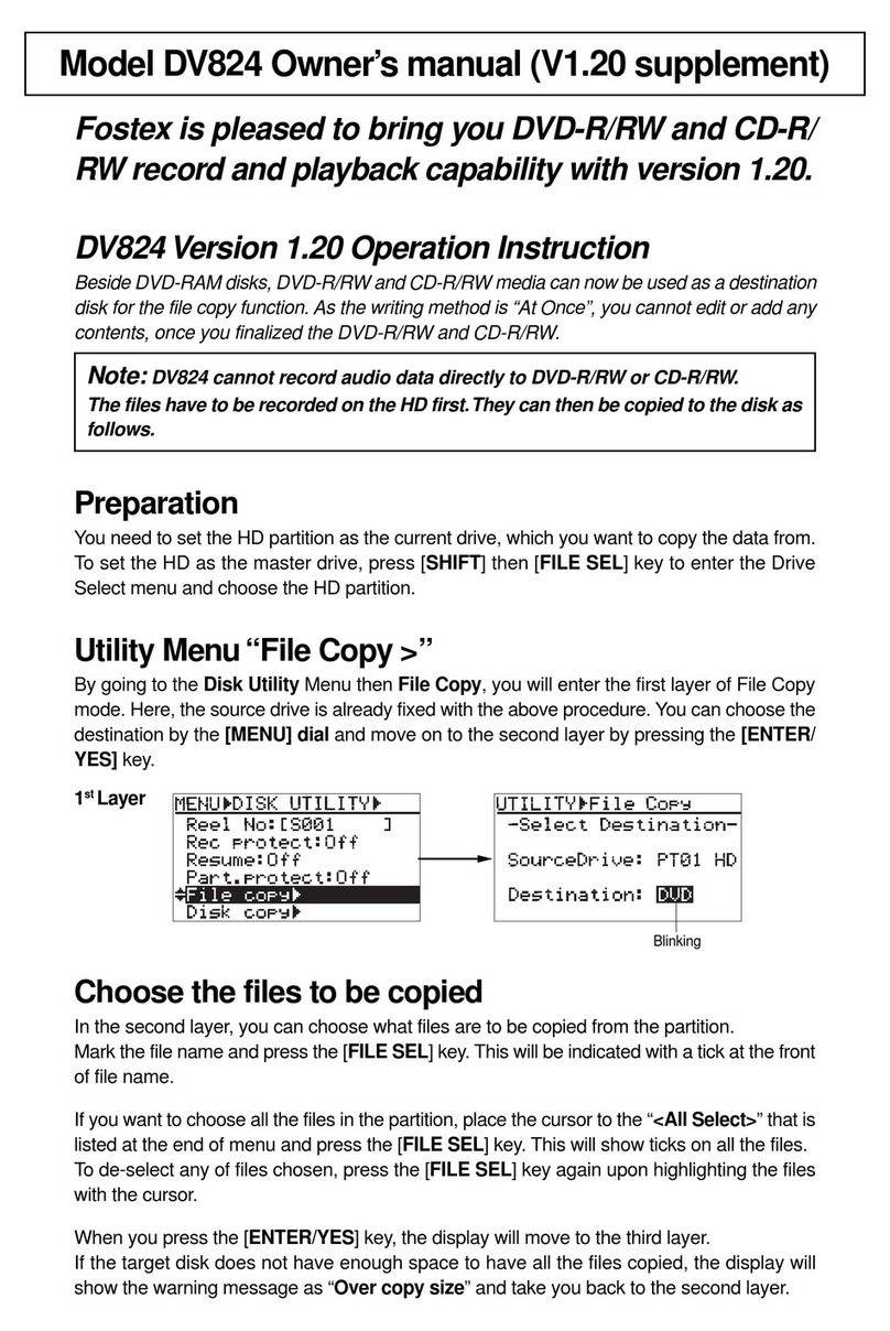
Fostex
Fostex DV-824 Configuration guide
Fostex
Fostex 8345 User manual
Fostex
Fostex 3050 User manual
Fostex
Fostex 8333 User manual
Fostex
Fostex 4010 User manual

Fostex
Fostex MR-16HD User manual

