6
STEP 1: Unpack filter unit, making sure to remove entire contents of the shipping container prior to disposal.
STEP 2: Placethe tanks intheuprightposition. Usetheprovided wrenchtoremove the fillport cap from the
filter tank (See Figure 6a, page 7) by turning it counter-clockwise.
STEP 3: If media is not already loaded, use the provided funnel to pour filter media(s) into the filter tank. If
using multiple filter media types, load in the order of heaviest (most dense) to lightest (least dense).
At least 14” of space MUST be left empty at the top of the filtertank to allow formedia bed expansion
during backwash and to prevent filter media from being discharged into the aeration tank.
STEP 4: Use a garden hose or bucket to fill the media tank with water.
IMPORTANT: Carbon, Filter Ag, Zeolite and Greensand Plus must be soaked for at least 2
hourspriortosubmittingittofullbackwashflowratetopreventlossofmediatoaerationtank.
STEP 5: Clean fillport threads to remove any filtermedia. Lubricatethe fillport cap o-ring with silicone grease.
Replace the fillport cap using the provided wrench.
STEP 6: Shutoffallwaterat mainsupply. Onprivatewellsystem,turnoffpowertopumpanddrainpressure
tank. Make certain pressure is relieved from complete system by opening nearest faucet to drain
system. SHUT OFF FUEL / ELECTRICAL SUPPLY TO WATER HEATER.
STEP 7: Plumb the water supply line to the unit's bypass valve inlet, located at the right rearas youface the
unit. There are a variety of installation fittings available. They are listed under Installation Fitting
Assemblies, pages21-23. Whenassemblingtheinstallationfittingpackage(inletandoutlet),connect
the fitting to the plumbing system first and then attach the nut, split ring, and "O" Ring. Heat from
soldering orsolventcements may damage the nut, split ring, or "O" Ring. Solder joints should be cool
and solvent cements should be set before installing the nut, split ring, and "O" Ring. Avoid getting
solder flux, primer, and solvent cement on any part of the "O" Rings, split rings, bypass valve, or
controlvalve.Ifthebuilding'selectricalsystemisgroundedtotheplumbing,install acoppergrounding
strap from the inlet to the outlet pipe. Plumbing must be done in accordance with all applicable local
codes. MAKE CERTAIN WATER ENTERS THROUGH INLET AND DISCHARGES THROUGH
OUTLET.
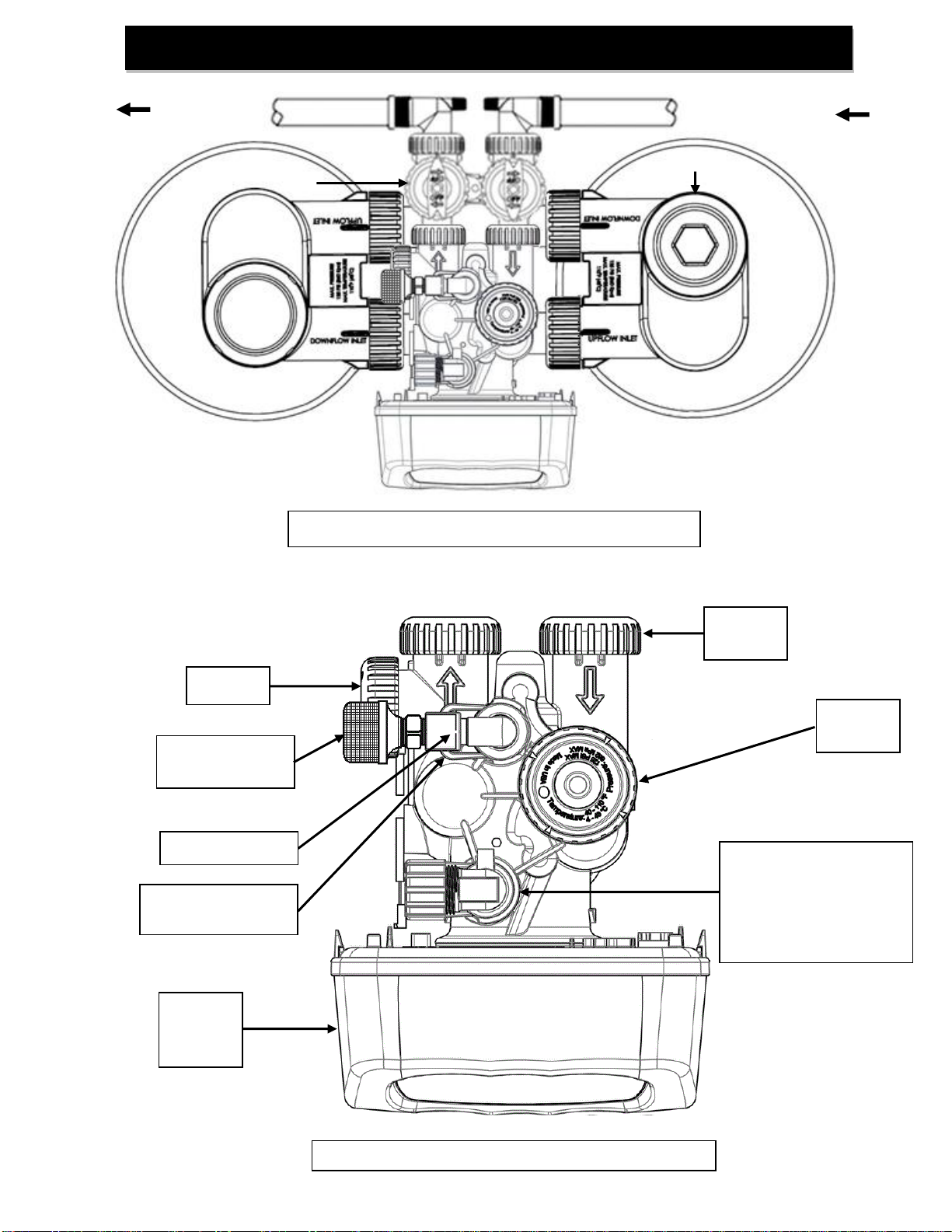
STEP 8: Apply thread tape to DLFC Assembly. Remove drain line flow control (DLFC) retainer clip (Figure
6b, Page 7) and remove the DLFC assembly from the valve body, (Figure 6b, Page 7). Apply thread
tapetothreads.Slidedrainfittingcompressionnutontoprovideddraintubingandplacethetubeinsert
insidetheendofthe tubing. Insert tubingendwithinsertintodrainelbowandtightenthecompression
nut onto the thread taped elbow. Reinsert DLFC assembly into the valve body, making certain it is
FULLY inserted before replacing the retaining clip.
STEP 9: Install drain line. Use the provided ½” I.D. polyethylene tubing (DO NOT USE FLEXIBLE VINYL
TUBING!) to run drain line from control valve DLFC fitting (Figure 6b, Page 7) to floor drain or sump
pitcapableofhandlingthebackwashrate of the filter(refertospecificationsandflowrateonpage 17)
or discard the compression fitting and use the ¾” NPT fitting to connect a rigid pipe drain line . If
backwash flow rate is greater than 7.5 gpm, use existing NPT connector with rigid drain line. There
must be an air gap at the end of the drain line to prevent siphoning of wastewater. Length of drain
line should be 15’ or less. AVOID OVERHEAD DRAINS.