FR100L&FR200L For Wire drawing machine
- 3 -
Chapter 1 Product Information
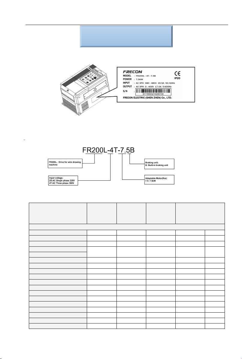
1.1 Nameplate information
Fig. 1-1 Nameplate
Model Instruction
Model numbers on name plate consist of numbers, symbols, and letters, to express its respective
series, suitable power type, power level and other information.
Fig 1-2 Model Explanation
1.2 FR100&FR200L Special Purpose Drive Model Selection
Model No. Power
capacity
KVA
Rated
Input
current
A
Rated
output
current
A
Applicable motor
kW HP
3-Phase:380V,50/60Hz Range:-15%~+30%
FR100L-4T-0.7B 1.5 3.4 2.5 0.75 1
FR100L-4T-1.5B 3 5.0 4.2 1.5 2
FR100L-4T-2.2B 4 5.8 5.5 2.2 3
FR100L-4T-4.0B 6 11 9.5 3.7、4 5
FR200L-4T-4.0B
FR200L-4T-5.5B 8.9 14.6 13 5.5 7.5
FR200L-4T-7.5B 11 20.5 17 7.5 10
FR200L-4T-011B 17 26 25 11 15
FR200L-4T-015B 21 35 32 15 20
FR200L-4T-018B 24 38.5 37 18.5 25
FR200L-4T-022B 30 46.5 45 22 30
FR200L-4T-030B 40 62 60 30 40
FR200L-4T-037 57 76 75 37 50
FR200L-4T-045 69 92 91 45 60
FR200L-4T-055 85 113 112 55 70
FR200L-4T-075 114 157 150 75 100
FR200L-4T-090 134 160* 176 90 125
FR200L-4T-110 160 190* 210 110 150