FR200F series Special Purpose Inverter
- 8 -
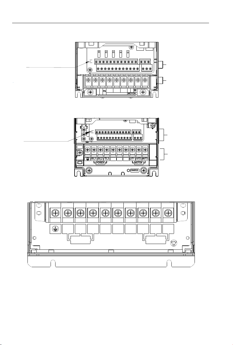
R/L1
U/T1 V/T2
(+)
(-)
POWER
MOTOR
S/L2 T/L3
P
POWER
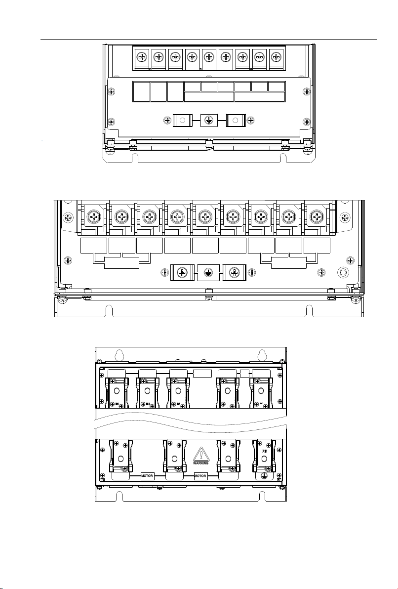
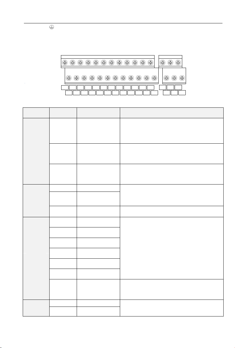
Figure 1-12 315~400kW main circuit terminals diagram
g:450-630kw main circuit terminals
RU/T1 V/T2 W/T3
(-)
POWER MOTOR
ST
DC+
DC
Figure 1-13 450~630kW main circuit terminals diagram
Table 1-3 circuit terminal functions
Designation and Function of Terminals
AC power input terminals for connecting to 3-phase
AC380V power supply.
AC output terminals of inverter for connecting to 3-phase AC
motor.
Positive and negative terminals of internal DC bus.
Connecting terminals of braking resistor. One end connected
to + and the other to PB.
Remarks: No phase sequence requirements on wiring of the input side of inverter. Wiring
Precautions:
1)Power input terminals R/L1、S/L2 、T/L3
◆The cable connection on the input side of the AC drive has no phase sequence requirement.
2)DC bus (+)、(-)
◆Terminals (+) and (-) of DC bus have residual voltage after the AC drive is switched off. After
indicator CHARGE goes off, wait at least 10 minutes before touching the equipment Otherwise, you
may get electric shock.
◆Do not connect the braking resistor directly to the DC bus. Otherwise, it may damage the AC drive
and even cause fire.
3)Braking resistor connection terminals (+)、PB
◆The cable length of the braking resistor shall be less than 5 m. Otherwise, it may damage the AC
drive.
4)AC drive output terminals U/T1、V/T2、W/T3
◆The capacitor or surge absorber cannot be connected to the output side of the AC drive. Otherwise,
it may cause frequent AC drive fault or even damage the AC drive.
If the motor cable is too long, electrical resonance will be generated due to the impact of distributed
capacitance. This will damage the motor insulation or generate higher leakage current, causing the AC
drive to trip in overcurrent protection. If the motor cable is greater than 100 m long, an AC output
reactor must be installed close to the AC drive.