Frecon PV Series User manual

PV series Solar Pumping Inverter
- 1 -
Preface
PV200 special inverters are developed for power supply of water pumps, based on the core
control arithmetic of FR200 vector control inverters, combined with the control requirements of PV
water pump application. The function of maximum power tracking, dormant at weak light, wake up at
strong light, high water level dormant, under-load pre-warning and other control protection functions
can ensure normal operation of water pumps according to the customers’ requirements to switch to the
grid power supply.
Please refer to this manual to commission the inverter, product maintenance refer to FR200 user
manual.
IMPORTANT NOTES
◆To illustrate the details of the products,pictures in this manual based on products with outer
casing or safety cover being removed. When using this product, please be sure to well install
outer casing or covering by the rules, and operating in accordance with the manual contents.
◆The illustrations in this manual are for illustration only and may vary with different products
you have ordered.
◆The company is committed to continuous improvement of products, product features will
continue to upgrade, the information provided is subject to change without notice.
◆If there is any questions when using, please contact our regional agents or our customer
service center:(+86-0755-33067999)
◆For other products, please visit our website. http://www.frecon.com.cn

PV series Solar Pumping Inverter
- 2 -

PV series Solar Pumping Inverter
- 3 -
Contents
Preface..........................................................................................................................................................- 1 -
Contents .......................................................................................................................................................- 3 -
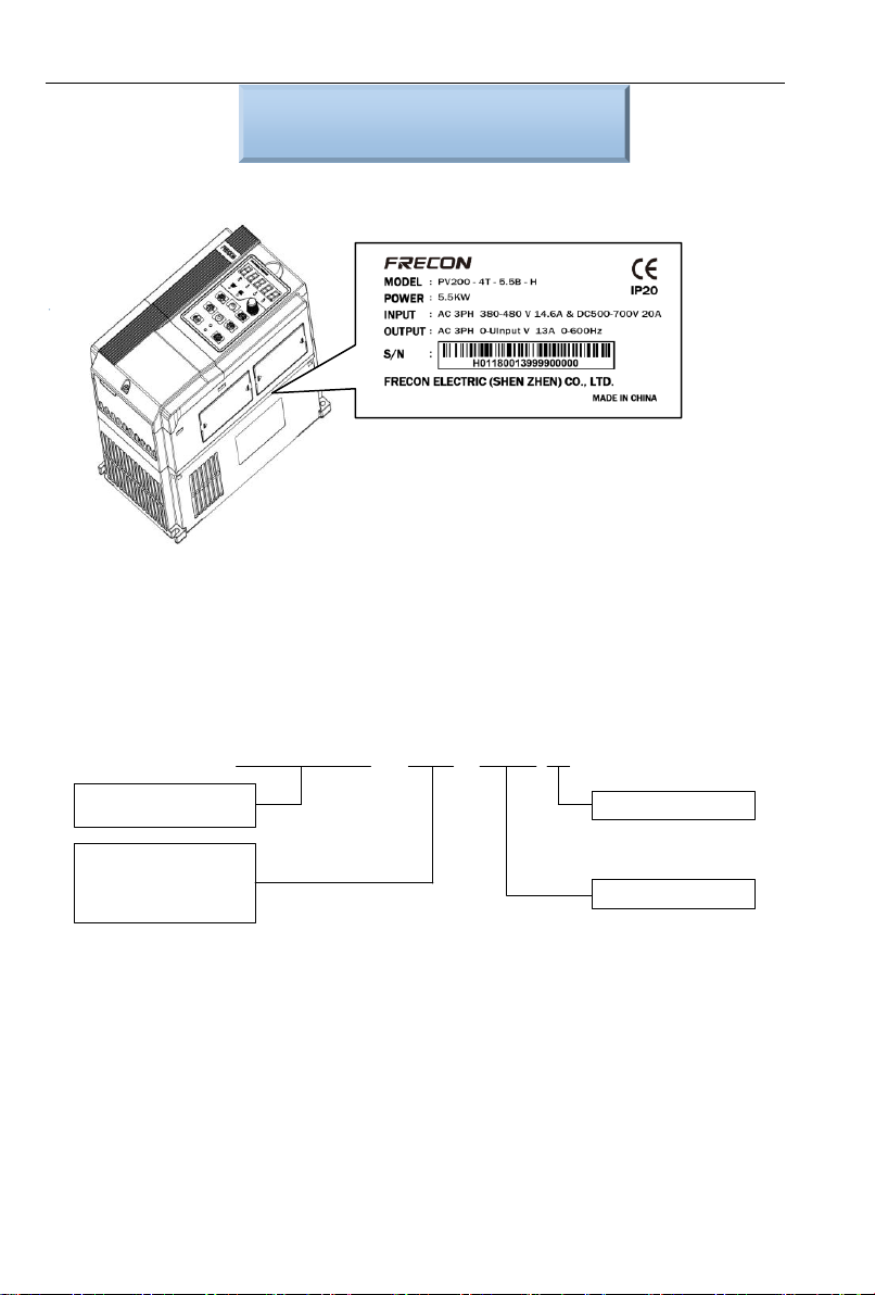
Chapter One Product Overview...............................................................................................................- 4 -
1.1 Name Plate........................................................................................................................................- 4 -
1.2 Product Specifications......................................................................................................................- 5 -
1.3 Dimension Drawing ..........................................................................................................................- 8 -
Chapter Two Commissioning Guide ....................................................................................................- 11 -
2.1 PV Panel Power Supply Commissioning.....................................................................................- 11 -
2.2 Grid or Generator power supply wirings......................................................................................- 13 -
2.3 Wiring diagram between VFD and single phase motor..............................................................- 15 -
2.4 Product Terminal Configuration....................................................................................................- 18 -
Chapter Three Function Parameters....................................................................................................- 22 -
3.1 The Basic Function Parameters....................................................................................................- 22 -
3.2 H00 Group: Detailed Explanation of Function Code ..................................................................- 39 -
Chapter Four Troubleshooting and Countermeasures....................................................................- 45 -

PV series Solar Pumping Inverter
- 4 -
Chapter One Product Overview
1.1 Name Plate
Figure 1-1 Name Plate
Model Instruction
Model numbers on name plate consist of numbers, symbols, and letters, to express its respective
series, suitable power type, power level and other information.
PV200-4T-2.2B
Products series Number
PV: Solar Pump Inverter
Input voltage level
4T: Three phase 380V
2T: Three phase 220V
2S: Single phase 220V
Braking Unit (Built-in )
Output power: 2.2kW
Figure 1-2 Product Model Naming Rules

PV series Solar Pumping Inverter
- 5 -
1.2 Product Specifications
1.2.1 Electric specification ofAC220V and DC310V Input product
Table 1-1 Electric specification of AC220V and DC310V Input product
Model No.
Recommended
Solar Array
Power kWP
Maximum
Input DC
Current A
Output
Current A
Adaptive
Motor kW
Size of
the Case
PV100-2S-0.2B
0.35
2.5
1.6
0.18, 0.2, 0.25
P1-1
PV100-2S-0.4B
0.6
4.5
2.5
0.37, 0.4
PV100-2S-0.7B
1.1
7.5
4.2
0.75
PV100-2S-1.5B
2.25
10
7.5
1.5
P1-2
PV100-2S-2.2B
3.3
18
9.5
2.2
PV100-2T-0.2B
0.35
2.5
1.6
0.18, 0.2, 0.25
P1-1
PV100-2T-0.4B
0.6
4.5
2.5
0.37, 0.4
PV100-2T-0.7B
1.1
7.5
4.2
0.75
PV100-2T-1.5B
2.25
10
7.5
1.5
P1-2
PV100-2T-2.2B
3.3
18
9.5
2.2
PV200-2T-0.7B
3.5
5.3
5
0.18, 0.2, 0.25
P2-1
PV200-2T-1.5B
5.5
8.5
8
0.37, 0.4
P2-2
PV200-2T-2.2B
7.5
11.6
11
2.2
PV200-2T-4.0B
11.7
18
17
4.0
PV200-2T-5.5B
17.3
26.5
25
5.5
P2-3
PV200-2T-7.5B
22
33.5
32
7.5
PV200-2T-011B
31
47.5
45
11
P2-4
PV200-2T-015B
41.5
63
60
15
PV200-2T-018
52
79
75
18
P2-5
PV200-2T-022
63
96
91
22
PV200-2T-030
77.5
118
112
30
P2-6
PV200-2T-037
104
158
150
37
PV200-2T-045
122
185
176
45
P2-7
PV200-2T-055
145
221
210
55
PV200-2T-075
173
263
250
75

PV series Solar Pumping Inverter
- 6 -
Input specification
PV Input
Maximum Input DC
Voltage
400VDC
Recommended Voc
Range
320~370VDC
Recommended MPPT
Voltage Range
250~350VDC
Starting Voltage
Range
120~400VDC
Grid or backup generator input
Input voltage
Single phase 220V(-15%~30%)
Output specification
Rated output voltage
3PH 220V
Output frequency
0~600.00Hz(default: 0~50.00Hz)
Protection
Built-in Protection
Lighting Protection, over-current, overvoltage, output phase-lose,
under-load, under-voltage, short circuit, overheating, water pump run
dry etc.
1.2.2 Electric specification ofAC 380V&DC 540V Input product
Table 1-2 Electric specification of AC 380V&DC 540V Input product
Model No.
Power
Capacity
kVA
Input
Current A
Output
Current A
Adaptive
Motor kW
Size of the
case
PV100-4T-0.7B
1.5
3.4
2.5
0.75
P1-2
PV100-4T-1.5B
3
5.0
4.2
1.5
PV100-4T-2.2B
4
5.8
5.5
2.2
PV100-4T-4.0B
6
11
9.5
3.7、4
PV200-4T-0.7B
1.5
3.4
2.5
0.75
P2-1
PV200-4T-1.5B
3
5.0
4.2
1.5
PV200-4T-2.2B
4
5.8
5.5
2.2
PV200-4T-4.0B
6
11
9.5
3.7、4
P2-2
PV200-4T-5.5B
8.9
14.6
13
5.5

PV series Solar Pumping Inverter
- 7 -
PV200-4T-7.5B
11
20.5
17
7.5
PV200-4T-011B
17
26
25
11
P2-3
PV200-4T-015B
21
35
32
15
PV200-4T-018B
24
38.5
37
18.5
P2-4
PV200-4T-022B
30
46.5
45
22
PV200-4T-030B
40
62
60
30
PV200-4T-037
57
76
75
37
P2-5
PV200-4T-045
69
92
91
45
PV200-4T-055
85
113
112
55
P2-6
PV200-4T-075
114
157
150
75
PV200-4T-090
134
160
176
90
P2-7
PV200-4T-110
160
190
210
110
PV200-4T-132
192
232
253
132
PV200-4T-160
231
282
304
160
P2-8
PV200-4T-185
240
326
350
185
PV200-4T-200
250
352
377
200
Input specification
PV Input
Maximum Input DC
Voltage
800VDC
Recommended Voc
Range
500~700VDC
Recommended MPPT
Voltage Range
450~600VDC
Starting Voltage Range
250~800VDC
Grid or backup generator input
Input Voltage
Three phase 380V(-15%~30%)
Output specification
Rated output voltage
3PH 380V
Output frequency
0~600.00Hz(Default 0~50.00Hz)

PV series Solar Pumping Inverter
- 8 -
Protection
Built-in Protection
Lighting Protection, over-current, overvoltage, output phase-lose,
under-load, under-voltage, short circuit, overheating, water pump run
dry etc.
General Parameters
Application Site
No direct sunshine, no dust、corrosive gas、combustible gas、oil mist、
steam、dripping or salinity etc.
Altitude
0~2000 m
Derated use above 1000m,per 100m, the rated output current
decrease 1%.
Environment
Temperature
-10℃~40℃(Environment Temperature be 40℃~50℃, please
keep derated use.)
Humidity
5~95%,non-condensation
Vibration
less than 5.9 m/s2(0.6g)
Storage Temperature
-20℃~+70℃
Efficiency
Rated Power Run≥93%
Installation
Wall or rail mounting
Protection Grade
IP20
Cooling
ForcedAir Cooling
1.3 Dimension Drawing
1.3.1 PV100
Table 1-3 PV100 Size Table

PV series Solar Pumping Inverter
- 9 -
Model No.
Dimensions and installation size(mm)
kG
W
H
D
W1
W2
H1
H2
H3
H4
d1
d2
P1-1
95
162
120
85
11
151.5
152
110.8
130
4.5
4.5
1.1
P1-2
110
173
135
100
11
163
163
121.8
140.5
4.5
5
1.5
1.3.2 PV200
a: 0.75~15kW Dimensions and wall mounting dimensions
W1
H1
H
W
D
4Xd
Figure 1-3 0.75~15kW Wall Installation Diagram
b: 18.5~200kW Dimensions and installation dimensions
W1
W
H1
H
D
4xd
H
WD
H1
dW1 W1
Figure 1-4 18.5~30kW Wall Mounting Diagram Figure 1-5 37~200kw Wall Mounting Diagram

PV series Solar Pumping Inverter
- 10 -
Table 1-4 Wall Mounting Size Table
Model No.
Dimensions and installation size(mm)
Weight
(Kg)
W
W1
H
H1
D
Installation
Aperture
P2-1
117
106.6
187
176.6
160
4.5
2.2
P2-2
146
131
249
236
177
5.5
3.2
P2-3
198
183
300
287
185
5.5
5.4
P2-4
255
176
459
443
220
7
15.5
P2-5
270
130
590
572
260
7
27.5
P2-6
357
230
590
572
260
7
37
P2-7
430
320
829.5
802
293
12
77.7
P2-8
500
180
1107
1078
328
14
138.5

PV series Solar Pumping Inverter
- 11 -
Chapter Two Commissioning Guide
2.1 PV Panel Power Supply Commissioning
1. Wiring drawings of below inverters shown as Figure 2-1: PV100 series, PV200 series 3 phase 220V
inverters with power lower than 15kw and 3 phase 380V inverters with power lower than 30kw.
PV panels Q1
R/L1
S/L2
T/L3
+24V
DI1
DI2
DI3
DI4
DI5
DI6
+10V
AI1
AI2
GND
PE
U/T1
V/T2
W/T3
485+
485-
GND
R1A
R1B
R1C
M
(-) (+) PB
PV200
Y2/HO
PLC
DI7/HI
COM
AI3
AO1
GND
+24V
Y1
AO2
GND
R2A
R2B
R2C
+
-
Note: The common
terminal of PV100 is
GND.
Tank
The water
level sensor
RUN/STOP
Short film
Operation panel
Figure 2-1 PV Cell Power Supply Wiring Diagram 1
Wire drawings of below inverters shown as Figure 2-2: PV200 series 3 phase 220V inverters with
power higher than 18kw and 3phase 380V inverters with power higher than 37kw.

PV series Solar Pumping Inverter
- 12 -
Tank
The water
level sensor
PV panels Q1
R/L1
S/L2
T/L3
+24V
DI1
DI2
DI3
DI4
DI5
DI6
+10V
AI1
AI2
GND
PE
U/T1
V/T2
W/T3
485+
485-
GND
R1A
R1B
R1C
RUN/STOP
M
(-) (+) PB
PV200
Operation panel
Y2/HO
PLC
DI7/HI
COM
AI3
AO1
GND
+24V
Y1
AO2
GND
R2A
R2B
R2C
+
-
Short film
Note: if it is connected to the power or
generator, the terminal short films
between R/S/T must be removed, or
will cause the fires, and even
casualties risk Short film
Figure 2-2 PV Cell Power Supply Wiring Diagram 2
1. Please wirings as Figure 2-1 or Figure 2-2 according to different inverter powers, check and confirm
the wirings to be correct, and then close Q1.
2. Setting the Motor Parameters
Setting the parameter of name plate on motor F08.01~F08.05。
3. Testing the water yield of pump
Press the operation key “RUN”, under normal circumstance of light strength, if the operation
frequency low or water yield less, which means the motor wiring may be reversed, please exchange
two wirings of motor.
4. System Effluent Speed PI Regulating
If the user has a high requirements for the effluent speed, PI parameters can be regulated
appropriately(H00.09~H00.10), the larger PI parameter, the stronger affection, the faster effluent,
but the larger fluctuation of motor frequency; Otherwise, the slower water effluent, the more steady
frequency of motor operation.
5. MPPT Tracing Speed Commissioning
H00.04 and H00.05 are respectively the lowest voltage and highest voltage under the MPPT mode,
the smaller the range between them two, the faster tracing the maximum power, but the premise if
that the bus voltage during normal operation must fall within this range, or the maximum power point
may not be tracked. Generally speaking, the factory default value is OK.

PV series Solar Pumping Inverter
- 13 -
6. Setting of fault point and fault delay reset time
If clients need to use the pre-warning of weak light, water-logged, under-load, failure monitoring
point, delay time and reset time, water-logged/controlled function can be set as H00.15~H00.19 on
demand; under-load function set as H00.20~H00.22; weak light function set as H00.13~H00.14.
Users also can adopt the default value.
7. Parameter setting after the system operation normally
When the water yield is normal, and system run steadily, the commissioning will be finished. And
then setting F02.00=1, change to terminal operation mode, setting failure auto reset times
F11.27=5.
2.2 Grid or Generator power supply wirings
Wiring drawings of below inverters shown as Figure 2-3: PV100 series, PV200 series 3 phase
220V inverters with power lower than 15kw and 3 phase 380V inverters with power lower than 30kw.
Q1
R/L1
S/L2
T/L3
+24V
DI1
DI2
DI3
DI4
DI5
DI6
+10V
AI1
AI2
GND
PE
U/T1
V/T2
W/T3
485+
485-
GND
R1A
R1B
R1C
Q2
M
(-) (+) PB
PV200
Y2/HO
PLC
DI7/HI
COM
AI3
AO1
GND
+24V
Y1
AO2
GND
R2A
R2B
R2C
PV panels
Note: The common
terminal of PV100 is
GND.
Grid or
generator set
PV Voltage
Given selection
Operation panel
Tank
The water
level sensor
RUN/STOP
Figure 2-3 Grid or Generator Power Supply Wiring Diagram 1
Wire drawings of below inverters shown as Figure 2-4: PV200 series 3 phase 220V inverters with
power higher than 18kw and 3phase 380V inverters with power higher than 37kw.

PV series Solar Pumping Inverter
- 14 -
PV panels Q1
R/L1
S/L2
T/L3
+24V
DI1
DI2
DI3
DI4
DI5
DI6
+10V
AI1
AI2
GND
PE
U/T1
V/T2
W/T3
485+
485-
GND
R1A
R1B
R1C
M
(-) (+) PB
PV200
Y2/HO
PLC
DI7/HI
COM
AI3
AO1
GND
+24V
Y1
AO2
GND
R2A
R2B
R2C
KM1
KM2
+
-
Note:KM1 and KM2
is a pair of
interlocking
contactors
Grid or
generator set
PV Voltage
Given selection
Operation panel
Tank
The water
level sensor
RUN/STOP
Short film
Figure 2-4 Grid or Generator Power Supply Wiring Diagram 2
1. Wirings as Figure 2-3 system wiring drawings according to inverters power, check and confirm
the connections to be correct.
2. Disconnect the switch Q1, and then close Q2, switch to grid or diesel engine power;
disconnect Q2, and then close Q1, switch to PV power supply; Figure 2-4 show inter-locking
connection between connector KM1 and KM2, KM1 close is PV power supply, KM2 close is
grid or generator power supply.
3. When grid or generator power supply, setting H00.01=0, power supplied by grid.
4. For water pump’s frequency, please refer to F01 group code, H00.02~H00.12 function code
does not work.
5. When change to PV power supply, setting F04.1=38 and close the terminal DI2 (or setting
H00.01=1).
Note:
When the bus input terminal does not install the diode protection, PV panel switch Q1 will be
prohibited to close together with grid power input switch Q2, or the panel will be damaged.

PV series Solar Pumping Inverter
- 15 -
2.3 Wiring diagram between VFD and single phase motor
2.3.1 Single phase motor introduction
Single phase motor generally means asynchronous single phase motor powered by single phase
AC 220V, there’re two phase winding in motor stator and motor rotor is common squirrel cage. The
distribution of two phase winding and different power supply will lead to different starting
characteristics and operating characteristics
Usually single phase motor is with single capacitor or double capacitor, photos of motor are as
below:
Figure 2-5 Motor with single capacitor and double capacitor
Single phase motor is consisted of main winding, secondary winding, capacitor and centrifugal
switch, internal wiring of single phase motor with single capacitor is as below:
Main
winding
Secondary
winding
Starting
capacitor
U1
U2
Z1
Z2
M
220VAC
Figure 2-6 Operation mode: Internal wiring of motor with single capacitor
Main
winding
Secondary
winding
Starting
capacitor
U1
U2
Z1
Z2
M
220VAC
Centrifugal
switch
Figure 2-7 Starting mode: Internal wiring of motor with single capacitor
Internal wiring of single phase motor with double capacitors is as below:

PV series Solar Pumping Inverter
- 16 -
Main winding Secondary
winding
Starting
capacitor
U1
U2
Z1
Z2
M
220VAC
Centrifugal
switch
Running
capacitor
Figure 2-8 Internal wiring of motor with double capacitors
Resistor starting mode single phase motor, and internal wiring is as below:
Main
winding
Secondary
winding
R
U1
U2
Z1
Z2
M
220VAC
Centrifugal
switch
Figure 2-9 Resistor starting mode: Internal wiring of motor
We can remove capacitors from above motors, and remaining 4 main and secondary winding
terminals as below:
Main winding Secondary
winding
U1
U2
Z1
Z2
M
Figure 2-10 Main and secondary winding of motor
2.3.2 Wiring between VFD and motor
Connect main and secondary winding of motor to inverter UVW, then inverter can work. But due
to the motor winding difference, motor forward wiring must be as below, if not cause motor too heat

PV series Solar Pumping Inverter
- 17 -
Main winding Secondary
winding
U1
U2
Z1
Z2
M
(-) (+) PB
PV100
KM1
L1
L2
U
V
W
220VAC
Figure 2-11 Forward wiring between PV100 VFD and motor
Motor reverse can’t be completed through parameter setting of inverter or change any two
phase wirings, motor reverse wiring must be as below:
Main
winding
Secondary
winding
U1
U2
Z1
Z2
M
(-) (+) PB
PV100
KM1
L1
L2
U
V
W
220VAC
Figure 2-12 Reverse wiring between PV100 VFD and motor
Motor forward and reverse wiring of 0.75Kw/220V PV200 is same with PV100, and wiring of
PV200 above 0.75kW are as below:
Main winding Secondary
winding
U1
U2
Z1
Z2
M
(-) (+) PB
PV200
KM1
L1
L2
U
V
W
220VAC
Figure 2-13 Forward wiring between VFD PV200 (Above 0.75Kw) and motor

PV series Solar Pumping Inverter
- 18 -
Main
winding
Secondary
winding
U1
U2
Z1
Z2
M
(-) (+) PB
PV200
KM1
L1
L2
U
V
W
220VAC
Figure 2-14 Reverse wiring between VFD PV200 (Above 0.75Kw) and motor
After wiring completed, need to set F08.00=2.
2.4 Product Terminal Configuration
2.4.1 Main Circuit Terminals
0.75~200KW main circuit terminals
Control circuit
terminals
Main circuit
terminals
Upload and
download interfaces
PB (+) (-)
RFI
Figure 2-15 0.75~200kW Main Circuit Terminal Diagram
Table 2-1 Functions of Inverter Main Circuit Terminals
Terminal Label
Description
R/L1、S/L2、T/L3
AC Power Input Terminal, connected to three-phase 380V AC power.
U/T1、V/T2、W/T3
Inverter AC output terminal, connected to three-phase AC motor
(+)、(-)
Respectively to be positive and negative terminal of internal DC bus
PB
Braking resistor connection terminals, one end connected to (+), the
other end of PB.
Ground terminal, connected to the earth.
2.4.2 Control Circuit Terminals

PV series Solar Pumping Inverter
- 19 -
DI1
+24V
DI2
PLC
DI3
COM
DI4
DI5
COM
DI6
Y1 Y2
+10V R1A R1B R1C
R2A R2B R2C
AO1
AI1
GND AI2 485+
AI3 485-
PE
DI7/HI
AO2 GND
Figure 2-16Control Terminals Diagram
Table 2-2 PV200 Inverter Control Circuit Terminal Functions
Type
Terminal Symbol
Terminal Name
Description
Power
Supply
+10V-GND
+10V Power
Supply
Output +10V Power Supply, Maximum
Output Current: 10mA. Generally use for
power supply of external potentiometer,
resistance range of potentiometer: 1~
5kΩ
+24V-COM
24V Power
Supply
Output +24V power supply, generally use
for power supply of digital input/output
terminal and external sensor, maximum
output current: 200mA.
PLC
External Power
Input Terminal
Factory default in connection with +24V,
when using an external signal to drive
DI1~DI7, PLC need to be connected to
external power, and disconnected with
+24V power terminal.
Analog
Input
AI1-GND
Analog Input
Terminal 1
Input Range: DC 0~10V/0~20mA,
selected by AI1、AI2 toggle switches on
control board. Input Impedance: 250kΩ
for voltage input, 250Ω for current input.
AI2-GND
Analog Input
Terminal 2
AI3-GND
Analog Input
Terminal 3
Input voltage range: DC -10~+10V
Input Impedance: 250kΩ
Digital
Input
DI1- COM
Digital Input
Terminal 1
Maximum input frequency: 200Hz
Input Impedance: 2.4kΩ
Voltage Range of level-input:9V~30V
DI2- COM
Digital Input
Terminal 2
DI3- COM
Digital Input
Terminal 3
DI4- COM
Digital Input
Terminal 4

PV series Solar Pumping Inverter
- 20 -
DI5- COM
Digital Input
Terminal 5
DI6- COM
Digital Input
Terminal 6
DI7/HI-COM
Digital Input
Terminal 7 or
high-speed
pulse input
Besides the features of DI1~DI6, DI7 also
can be the channel of high-speed pulse
input. Maximum input frequency: 100kHz.
Analog
Output
AO1-GND
Analog Output
Terminal 1
Output range:DC 0~10V/0~20mA,
selected by A01、A02 toggle switches on
control board. Impedance required≥10kΩ
AO2-GND
Analog Output
Terminal 2
Digital
Output
Y1-COM
Open Collector
Output 1
Voltage Range: 0~24V
Current Range: 0~50mA
Y2/HO-COM
Open Collector
Output 2or
high-speed
pulse output
Apart from Y1 characteristics, Y2 also
can be the channel of high-speed pulse
input. Maximum output frequency:
100kHz.
Relay
Output
R1A-R1C
normal open
terminal
Contact driving ability:
AC250V,3A,COSØ=0.4。
DC 30V,1A
R1B-R1C
normal close
terminal
R2A-R2C
normal open
terminal
R2B-R2C
normal close
terminal
485
Communi
cation
485+-485-
485
Communication
Terminals
Speed:
4800/9600/19200/38400/57600/115200b
ps.
RS485 toggle switch on control board,
setting the terminal matching-resister
GND
485
Communication
Shield Ground
Shielded
PE
Shield
Grounding
It’s use for grounding the shield of
terminal-wire
Aid
Interface
External
Keyboard
Interface
When connected to operation board, the
longest communication distance is up to
50m, adopt the standard network cable
(RJ45)
This manual suits for next models
52
Table of contents
Other Frecon Inverter manuals
Popular Inverter manuals by other brands

CE+T Power
CE+T Power BRAVO 25 user manual

Endress
Endress ESE 608 DHG ES DI DUPLEX operating instructions

Omron
Omron VARISPEED F7 quick guide

Mitsubishi Electric
Mitsubishi Electric 800 Series instruction manual

SolarEdge
SolarEdge SEK-I Series installation guide

Selectronic
Selectronic SP PRO 2i Series instruction manual