Fresh INTELLIVENT CELSIUS User manual

Designed and manufactured
by Fresh in Sweden
MANUAL
INTELLIVENT
®
CELSIUS
EN
DE
FR
ES
NL
IT

Thank you for choosing this product from Fresh.
Before installing and using the fan, read through this manual /
these instruction for use.
Then keep it in a safe place so that you can use it for future
reference.
Safety information!
Children aged 8 and above as well
as persons with reduced physical,
sensory or mental capacity or who
do not have the necessary experience
or know-how may use this
equipment if they are supervised or
given sucient instruction in how
to use the equipment safely and
have understood the risks involved.
Children must not play with this
equipment. Cleaning and
maintenance must not be performed
by unsupervised children.
2

4 Description of functions
5 Installation guide
1 Contents
2 Installation
3 Connection
4 Connecting a pull cord switch
5 Factory setting
6 Setting the fan
9 Functional description
10 Advanced functions
• Activation of constant operation
• Calibration of thermostat
• Calibration of the dierence between the
cut-in and cut-o temperature (hysteresis)
12 LED indicators
13 Maintenance
15 Warranty
15 Recycling
16 Accessories
17 Technical data
18 Troubleshooting guide
EN
3

Description of functions
• Thermostat
Fresh Celsius is equipped with a built-in thermostat which
means that the fan starts when the temperature reaches
the set value.
• Speed control
The integral speed control allows you to adjust the noise
level and capacity to meet your needs.
• Continuous operation
Leave the fan running continuously if you need air
circulation in the home.
• Pause function
The fan can be paused for one hour using the power cord.
• Multi-pole switch
The fan is tted with an approved multi-pole switch, which
means that an external switch is not required.
• LED indicators
An LED indicates which mode the fan is in at any one time.
• 12-volt motor
The motor is a long-life motor, with a life span of approx.
60,000 hours. This type of motor also runs silently.
A more detailed functional description appears on page 9.
4

Installation guide
1 Contents
The packaging should contain the following:
• Fan
• 2 adapters, 1 x Ø98 mm and 1 x Ø118 mm
• Manual
• Accessory bag with 4 screws and plugs, a pull cord with
toggle, and insulation for the standard cable type (FK)
2 Installation
The fan can be installed on a wall or on a ceiling. See the
diagram below for installation dimensions. The fan must
not be installed in an environment where the temperature
exceeds 50°C. Attach an appropriate adapter to the fan’s
chassis, Ø98 (1) for a Ø100 duct or Ø118 (2) for a Ø125 duct.
The fan can also be installed
and used without an adapter,
so that it is mounted com-
pletely on the surface, e.g. in
the case of ducts less than
Ø98.
When installing the fan, check
that there is a seal between
the pipe/duct and wall/ceiling
to prevent air from penetrating the wall or ceiling. Use the
accompanying screw and plug, if necessary.
1
2
Ø100 alt. Ø125
45
55
Min 120
Min 80
45
55
#124
Alt. x4
x4
EN
5

3 Wiring
• Installation work should be performed by a qualied
electrician.
• The fan is double insulated and must not be earthed.
• The fan is tted with an approved multi-pole switch and
does not require a pre-wired external switch.
1 Push the safety switch up to position 0 - OFF.
2 The cable can be installed either along the surface using
entries A in the chassis or concealed using entries B in the
chassis. Both options are shown below. Use the insulating
sleeve supplied for the cable (FK).
3 If you use any of the B inlets, remove the concealed round
plastic cover by tapping inside the break-o notch from
the inside out to the back with a screwdriver, for example.
A
A
A
A
B
B
B
B
ON
OFF
SL N L
L
N
SL N L
L
N
Alt. 2Alt. 1
Alt. 1 Standard
Alt. 2 for forcing (see page 11)
Cable entries
A = surface
B = concealed
Wiring diagram
6

4 Connecting the pull cord switch
If desired, a pull cord can be installed for activating the pause
function and to help calibrate the fan.
Remove the mounting plate using a screwdriver, for example,
and thread the accompanying pull cord through the hole.
• Once installation is complete, push the safety switch down
to position I – ON, to make the fan active again.
When the fan is connected to the power supply, it performs a
self-test where electronics, LEDs and operation of the motor are
all tested.
The fan is now ready for use.
EN
7

5 Factory setting
• temperature – 26°C
• speed – step 5 (70% of max)
• constant operation – o
Re-setting to factory settings
Keep the SPEED minus key pressed in
for at least ve seconds.
6 Setting the fan
You can use the control panel to quickly
and easily set those parameters you
require:
1. Starting temperature.
Set the desired starting temperature using the plus and
minus TEMP keys
2. Speed
Set the desired speed using the plus and minus keys (SPEED).
The fan is now ready for use. For more advanced settings,
go to page 10.
16
18
20
22
24
26
28
30
TEMP
C0
SPEED
step
1
2
3
4
5
6
7
8
SPEED
TEMP
CELSIUS
8

Functional description
Heat transfer / thermostat
The Celsius is tted with an integrated electronic thermostat.
This starts the fan when the temperature exceeds the preset
value. The fan can easily be adjusted to start between 16 and
30°C. The factory setting for the starting point is approx. 26°C.
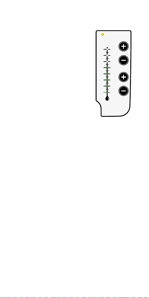
The starting point is adjusted using the plus and minus keys
(TEMP) on the control panel.
The start value is indicated by the LED lamps on the thermo-
meter scale. When the thermostat activates the fan, the
yellow indicator lamp lights up.
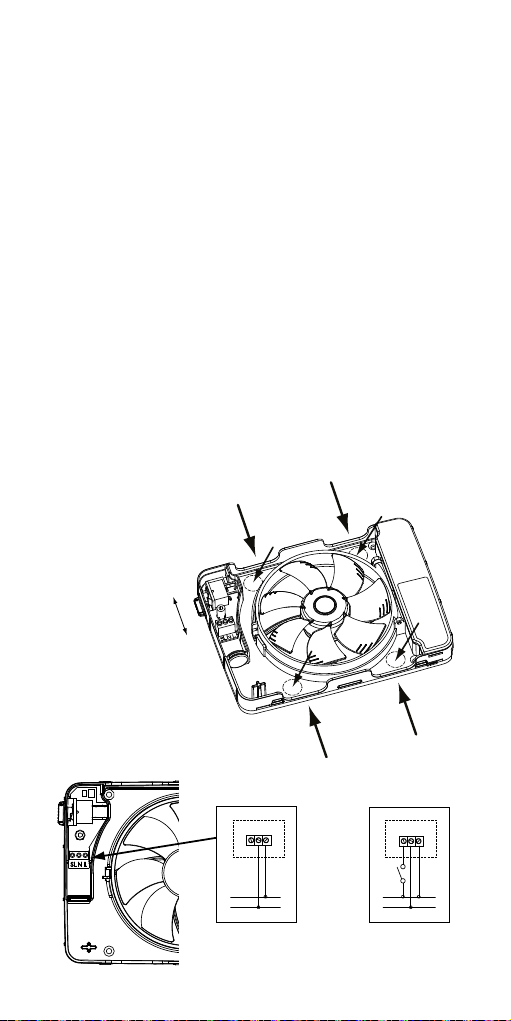
Before the starting point is adjusted, the fan must be
connected for at least 30 minutes. This is in order for the
fan’s electrics to reach operating temperature.
RPM settings
The fan speed can be set to anything from 50% up to maxi-
mum speed. The plus and minus keys (SPEED) on the control
panel are used to set the preferred speed.
The speed is indicated by a column of LED lamps labelled
with a scale from 1 to 8. If you adjust the speed down to zero
(no lamp is lit), the fan stops.
Constant operation
The Celsius also has a constant operation function.
The fan runs continuously at a preset speed.
The yellow indicator lamp does not light up during constant
operation. It is rst lit when the thermostat is activated, the
fan then reaches the speed set for heat transfer.
Pause function
The pause function means that the fan stops (whichever
mode it is in) and remains inactive for one hour. The pause
function is activated by pulling the power cord; after one
hour the fan resumes operation. During this time the yellow
indicator lamp ashes. The pause function can be cancelled
by pulling the cord a second time.
EN
9

Advanced functions
Activation of constant operation
• Pull the power switch mechanism once
- the yellow indicator lamp ashes.
• Set the desired speed using the plus and minus keys (SPEED).
• Pull the power switch mechanism
– yellow indicator lamp stops ashing.
The fan now runs constantly even when the fan's thermostat
function is not activated. This means that the fan can operate
at two individual speeds at constant operation or thermostat
operation if desired.
Switching o constant operation
• Pull the power switch mechanism once
- the yellow indicator lamp ashes.
• Press the minus key (SPEED) until no green indicator lamps
are lit – the fan stops.
• Pull the power switch mechanism
– yellow indicator lamp stops ashing.
Calibration of thermostat
There may occasionally be a need to calibrate the thermostat.
The fan must be connected for at least 30 minutes before-
hand in order for the electronics to reach their operating
temperature.
• Press in one of the plus or minus (TEMP) buttons.
• Then pull the power switch mechanism once
• Release the button – the yellow indicator lamp ashes
slowly
You are now in programming mode
Use the TEMP +/- buttons to adjust the temperature to the
room/desired level.
The temperature is indicated by one or two indicator lamps.
Even degrees are displayed with one lamp on the temperature
scale and uneven degrees with two lamps, one above and
one below the desired level. Pull the power switch mechanism
again and the yellow indicator lamp stops ashing. Calibration
is now complete.
10

Calibration of the dierence between the cut-in and cut-
o temperature (hysteresis)
It may occasionally be necessary to adjust the dierent
between the cut-in and cut-o temperature (hysteresis).
The default value is 1.5°C.
• Press in one of the plus or minus (SPEED) buttons.
• Then pull the power switch mechanism once
• Release the button – the yellow indicator lamp ashes
quickly
You are now in programming mode
Now use the SPEED +/- buttons to adjust the temperature
dierence to the desired level.
The temperature is indicated by one or two indicator lamps.
Whole degrees are displayed with one lamp on the speed
scale and half degrees with two lamps, one above and one
below the desired level. Each step adjusts the hysteresis by
half a degree.
For example, if a dierence of 2.5°C is desired, the tempera-
ture is increased until the indicator lamp 2 and 3 is lit on the
speed scale.
The lowest hysteresis is 0.5°C as no lamps are lit.
When you have nished, pull the cord/cord mechanism once
more and the yellow indicator lamp stops ashing.
Calibration of hysteresis is now complete.
Forcing with ignition wire (control phase SL)
The Celsius also has a forcing function. To gain access to this,
the fan must be connected with ignition wire (control phase)
to SL on the plinth.
Function:
Power supplied (current to SL) via an extern switch causes
the fan to run at max. speed independently of other active
functions.
When the switch is turned o, the fan returns to the
programmed function.
EN
11

LED indicators
LED - what is the fan doing?
The fan uses a yellow indicator lamp to indicate heat transfer
– the thermostat is switched on.
The yellow indicator lamp also has three dierent ashing
speeds.
• Slowly – Calibrating the thermostat
• Medium – The pause function is activated
• Fast – adjustment of the dierence between the cut-in
and cut-o temperature (hysteresis).
If the constant operation function is used, no lamp lights up.
12

Maintenance
The Fresh Celsius is designed to work eciently for many
years.
The fan needs to be cleaned at regular intervals if it is
to function properly. These intervals are determined by
duration of fan operation and air quality.
Clean the fan at least twice a year, or as required.
Disconnect the power supply to the fan by pushing the multi-
pole switch up to position O - OFF.
The fan is tted with a removable impeller. Press in the centre
using your thumb, grip the fan wings and pull the impeller
o. The fan's "swing out" function is also useful, as it provides
easy access to the duct. Press the motor ring’s quick-release
catch and swing out the motor/impeller.
Clean the duct/pipe if there is any dirt present inside. Failure
to do this may result in a risk of impaired capacity.
OFF
EN
13

When cleaning the fan, pay particular attention to the fan
wings if these are dirty. There is otherwise a risk of imbal-
ance and hence increased noise and a reduced life span
for the motor.
The easiest way to clean the impeller is using a brush and a
weakly diluted washing up liquid.
Dry o the impeller after cleaning.
Clean the fan cover with a polishing cloth moistened with
water and possibly a mild detergent.
NB! Never use solvents or similar products on any part of
the fan, as there is a risk of them damaging the fan's plastic
components!
Never submerge the fan in water, as there is a risk that this
could seriously damage the fan.
After cleaning, swing the motor mount ring back into posi-
tion and lock it by securing the snap-in catch. Remount the
impeller, press in until it clicks into place. Switch the multi-
pole switch back on by moving it down to position 1 - ON.
If maintenance of the fan is not performed as specied
above, the product guarantee will be void.
Klick!
14

Warranty
We provide a 5 year guarantee against
manufacturing defects.
For the warranty to be valid, proof of purchase is required
and the fan:
- must be assembled and installed in accordance with the
installation guide in this manual
- must have been maintained according to the maintenance
instructions in this manual
- must be installed in a normal residential environment
- must be connected to a voltage of 100-240 V AC
- must not have been exposed to lightning or abnormal
power surges
- must not be have been subjected to tampering
- must have been installed in a zone rated as IP44
- must not have been installed in an environment where the
temperature exceeded 50° Celsius.
Complaints concerning the product are to be made to the point
of purchase.
Recycling
The product is marked with the WEEE symbol, which indicates
that it must not be disposed of with household waste, but
must be recycled at a suitable recycling location in the local
municipality.
Fresh AB is a part of Sweden’s national
recycling system, in accordance with
the European WEEE Directive.
For more information, see www.fresh.eu
EN
15

Accessories
There are a number of accessories available for Fresh Celsius
to help you, as a user, install the product as smoothly as pos-
sible. Below are some examples of accessories.
Inlet kit
100
Tubes for sizes
100 and 125
Cover plate 190 x 240 mm
white and black
Plastic grille for sizes
100 and 125
Metal grille for sizes
100 and 125
16

Duct
dimensions
Speed steps
1-8
Capacity,
free blowing
(m³/h)
Sound
pressure level
3 m (dB A)
Ø 100 1 32 10
Ø 100 2 41 12
Ø 100 3 49 14
Ø 100 4 61 18
Ø 100 5 70 21
Ø 100 6 77 23
Ø 100 7 85 25
Ø 100 8 105 28
Ø125 1 41 11
Ø125 2 55 13
Ø125 3 64 14.5
Ø125 4 79 18
Ø125 5 89 21
Ø125 6 98 24
Ø125 7 108 27
Ø 125 8 134 29
Maximum capacity 134 m³/h
Sound pressure level 3 m (Speed incre-
ment 5) 21 dB(A)
Power consumption 2.1 - 5.5 W
Mounting dimensions in wall 0-30 mm
Holes 105-130 mm
Material ABS plastic
Protection rating IP44
Insulation class
Voltage 100-240 V
Frequency 50-60 Hz
Certificates
35
30
25
20
15
10
5
0
0 50 100 150
Ø98 step 5
Ø118 step 5
Ø98 max speed
Ø118 max speed
Pa
m³/h
Capacity
Technical data
EN
17

TROUBLESHOOTING GUIDE
The fan does not start
The fan is newly installed and has never been started
• Check that the fan impeller runs freely by spinning it.
• Check the position of the safety switch.
It should be in position I, which corresponds to On.
• Remove the cover and disconnect the power supply to
the fan by moving the safety switch to 0. Then return the
switch to 1.
• Check that there is voltage at terminal block L. (May only
be performed by an electrician.)
• Check that neutral is properly connected by measuring
the voltage across L-N. (May only be performed by an
electrician.)
If the fan still fails to initiate the startup sequence, which in-
volves the LEDs lighting up in sequence and the motor starting
after a short time, you can return the fan as long as it is within
the warranty period and you have a receipt. See Guarantee on
page 15.
The fan has been in use for some time
• Check that the fan impeller runs freely by spinning it.
• Remove the cover and restart the fan by turning the safety
switch o and then on again. Leave the fan switched o
for about 3 seconds before switching it back on.
• Perform a factory reset by holding the SPEED minus button
for at least ve seconds.
If the LEDs light up in sequence but the motor does not start, you
can return the fan as long as it is within the warranty period and
you have a receipt. See Guarantee on page 15.
The fan has been cleaned
• Check that the fan impeller runs freely by spinning it.
• Check the position of the safety switch.
It should be in position I, which corresponds to On.
18

The fan runs non-stop
No LEDs on
• Check that the“constant operation”function is not
activated. See page 10.
• Remove the cover and disconnect the power supply to
the fan by moving the safety switch to 0. Then return the
switch to I.
• Perform a factory reset by holding the SPEED minus button
for at least ve seconds.
Yellow LED is constantly on
• Remove the cover and disconnect the power supply to
the fan by moving the safety switch to 0. Then return the
switch to I.
• Check calibration and settings for thermostat.
• Then adjust the thermostat’s temperature to higher than
that in the room if the stove is not lit.
The recommended starting temperature is at least 25°C
If the fan still runs nonstop, you can return the fan as long as
it is within the warranty period and you have a receipt. See
Guarantee on page 15.
Other faults
The fan does not work as described
• Remove the cover and disconnect the power supply to
the fan by moving the safety switch to 0. Then return the
switch to I on/o.
• Perform a factory reset by holding the SPEED minus button
for at least ve seconds.
If the fan still does not work as described in this manual, contact
the retailer or Fresh AB.
EN
19

Vielen Dank, dass Sie sich für dieses Produkt von Fresh
entschieden haben.
Bitte lesen Sie sich diese Bedienungsanleitung sorgfältig
durch, bevor Sie den Lüfter installieren und in Gebrauch
nehmen.
Verwahren Sie sie anschließend sicher auf, so dass Sie im
Bedarfsfall darauf zurückgreifen können.
Sicherheitshinweis!
Kinder ab 8 Jahren sowie Personen
mit eingeschränkten physischen,
sensorischen oder geistigen
Fähigkeiten bzw. ohne erforderliche
Erfahrung oder Kenntnisse dürfen
das Gerät unter der Voraussetzung
verwenden, dass sie ausreichend
beaufsichtigt werden oder bezüglich
des sicheren Gebrauchs des Gerätes
unterwiesen wurden und die daraus
resultierenden Gefahren verstehen.
Das Gerät ist kein Spielzeug. Kinder
dürfen das Gerät nicht ohne Aufsicht
reinigen oder warten.
2
Table of contents
Languages:
Other Fresh Fan manuals

Fresh
Fresh TF100 User manual

Fresh
Fresh TL100DE User manual

Fresh
Fresh Intellivent Sky User manual

Fresh
Fresh ID100 User manual

Fresh
Fresh F100 Manual

Fresh
Fresh INTELLIVENT User manual

Fresh
Fresh TF Series User manual

Fresh
Fresh Intellivent Sky User manual

Fresh
Fresh DF100 User manual

Fresh
Fresh INTELLIVENT 2.0 User manual
Popular Fan manuals by other brands

minkaAire
minkaAire SUNDOWNER F589-TCL Instruction manual warranty certificate

S&P
S&P SILENT DUAL 100 manual

Mitsubishi Electric
Mitsubishi Electric Fresh Master GUF-50RDH4 operating instructions

Bosch
Bosch DRR18BS25 User manual and assembly instructions

Fan-Tastic Vent
Fan-Tastic Vent 7350 installation instructions

Field Controls
Field Controls 1428000 installation instructions