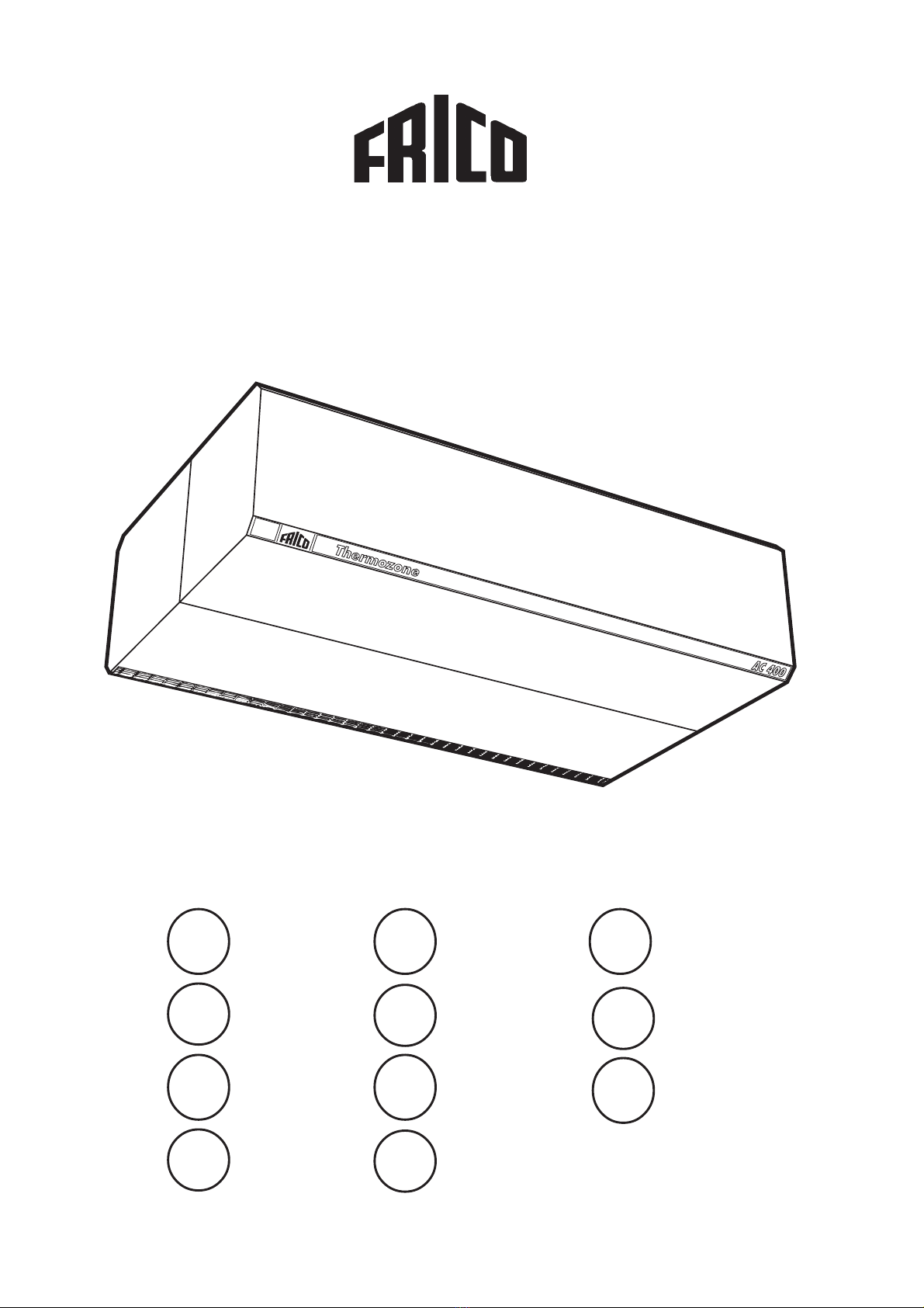
Frico Thermozone AC 400 User manual

Thermozone AC 400
SE
... 12
... 8
NO
FR
... 28
... 24 PL ... 40
... 44
IT
FI
... 20
...16
GB
NL
... 36
... 32
RU
ES ... 48
DE

Thermozone AC 400
2
Thermozone AC 400
1000 / 1665
335
ø 11
ø 20
915 / 1640
710
400
490
1070
1120
945
770
min 200
Fig 1.
Fig 2.
Fig 3.
Fig 4.
Fig 5.

Thermozone AC 400
3
Thermozone AC 400
Thermozone AC 400
45
Fig 6.

Thermozone AC 400
4
7531
2468
ACR 304 01357
1
2
3
4
KS115.1
~
M
AC 401, -402 230V ~
~
M~
M~
M~
M
NL
PTC
123456NL
NLNL
7 8 9
230V~
AGB 304
~
N
2221AG
~
N
2221AG
AC 401, -402
1234NL
230V~
AC 401, -402
1234NL
230V~
9
KS116.1 KS117.1

Thermozone AC 400
AC 401, -402
123456NL
230V~
AGB 304
34 3536 373833
ACR 3042
32
1234
31
AC 401, -402 456
9
9
KS109.1
5
7531
2468
ACR 304
Relay
Relay if Thermozone I > 6A
motors
AGB 304
AC 401, -402
123456NL
AC 401, -402
4569
9
230V~
KS110.1

Thermozone AC 400
7531
2468
ACR 304
Relay
Relay if Thermozone I > 6A
motors
AGB 304
AC 412, -418 123456NL 7
321
LLL
12131415
10
AC 412, -418 456
321
LLL
400V 3~ / 230V 3~
1213141510
AC 412, -418 456
321
LLL
400V 3~ / 230V 3~
12131415
10
230V~
KS113.1
1
2
32
3
1
Hi
Lo
KRT 2800,
16A 230V~ / 10A 400V~
400V 3~ / 230V 3~
6
7531
2468
ACR 304
0
1357
1
2
3
4
321
400V 3~
LLL
K2 K3
230 V 3~
K1
10111213 1514
400V 3~ / 230V 3~
51
2
6
EV 300
62
~
M
AC 412, -418 400V 3(N)~ / 230V 3~
~
M~
M~
M~
M
NL
PTC
123456NL
NLNL
789
230V~
2
32
3
1
Hi
Lo
KRT 2800,
16A 230V~ / 10A 400V~
KS112.1

Thermozone AC 400
7
AC 412, -418 123456NL 7
230V~
AC 412, -418 456
321LLL
400V 3~ / 230V 3~
12131415
10
321LLL
400V 3~ / 230V 3~
12131415
10
51
2
6
EV 300
1
2
32
3
1
Hi
Lo
KRT 2800,
16A 230V~ / 10A 400V~
AGB 304
34 35 36 37 3833
ACR 3042
32
1234
31
AC 412, -418 456 321LLL
1213141510
400V 3~ / 230V 3~
KS119.1
MA120.1

Thermozone AC 400
Application area
The Thermozone AC 400 air curtains are
intended for stationary installation above or
at the side of entrance and smaller doors with
a height of between 3 and 4.5 metres.
The Thermozone AC 400 is supplied with
or without heating elements. Electric heat
can be added to units without heat
afterwards.
The efficiency of the air curtains is
dependent on the difference of air pressure
and temperature (between the rooms that are
separeated by the air curtain) and pressure
caused by wind.
The protection class of AC 400 is IP 24,
drip-proof design.
Operation
The air is drawn in from the upper and under
side of the unit and is blown out at high
velocity across the doorway, providing a
protective air shield. The air shield
minimizes heat and cold air leakage.
When mounted on supplied brackets, the
units can be tilted in an angel where the size
of load on the door in question is taken into
account. The more load caused by negativ
pressure, temperature differences and wind,
the more should the air stream be directed
outwards.
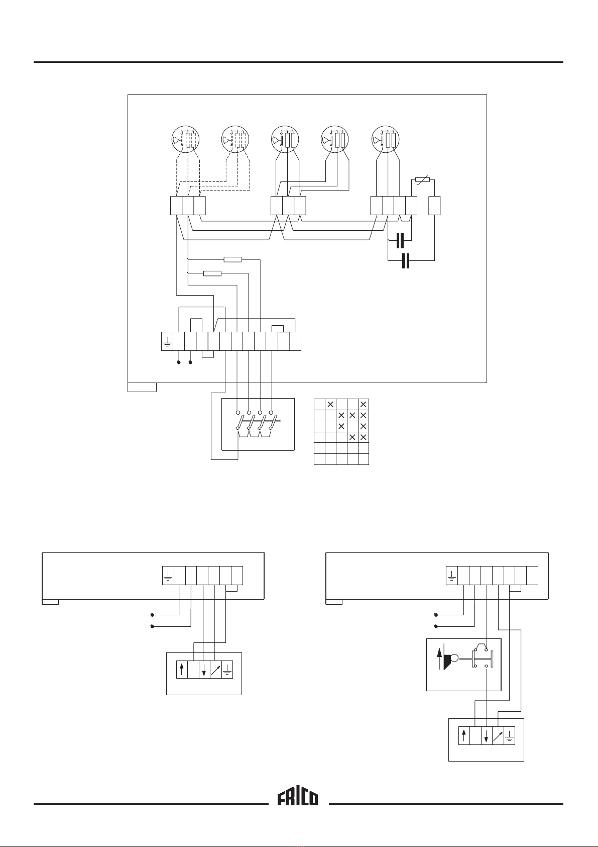
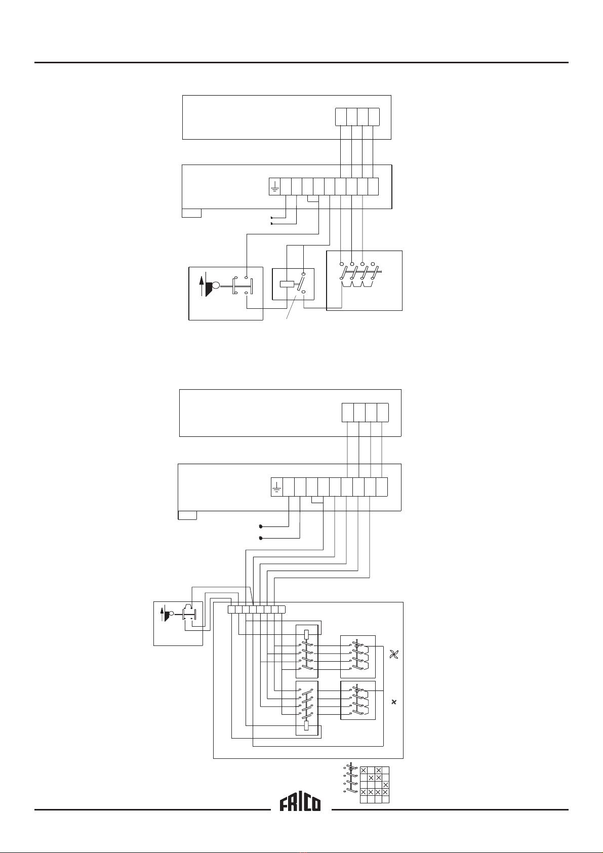
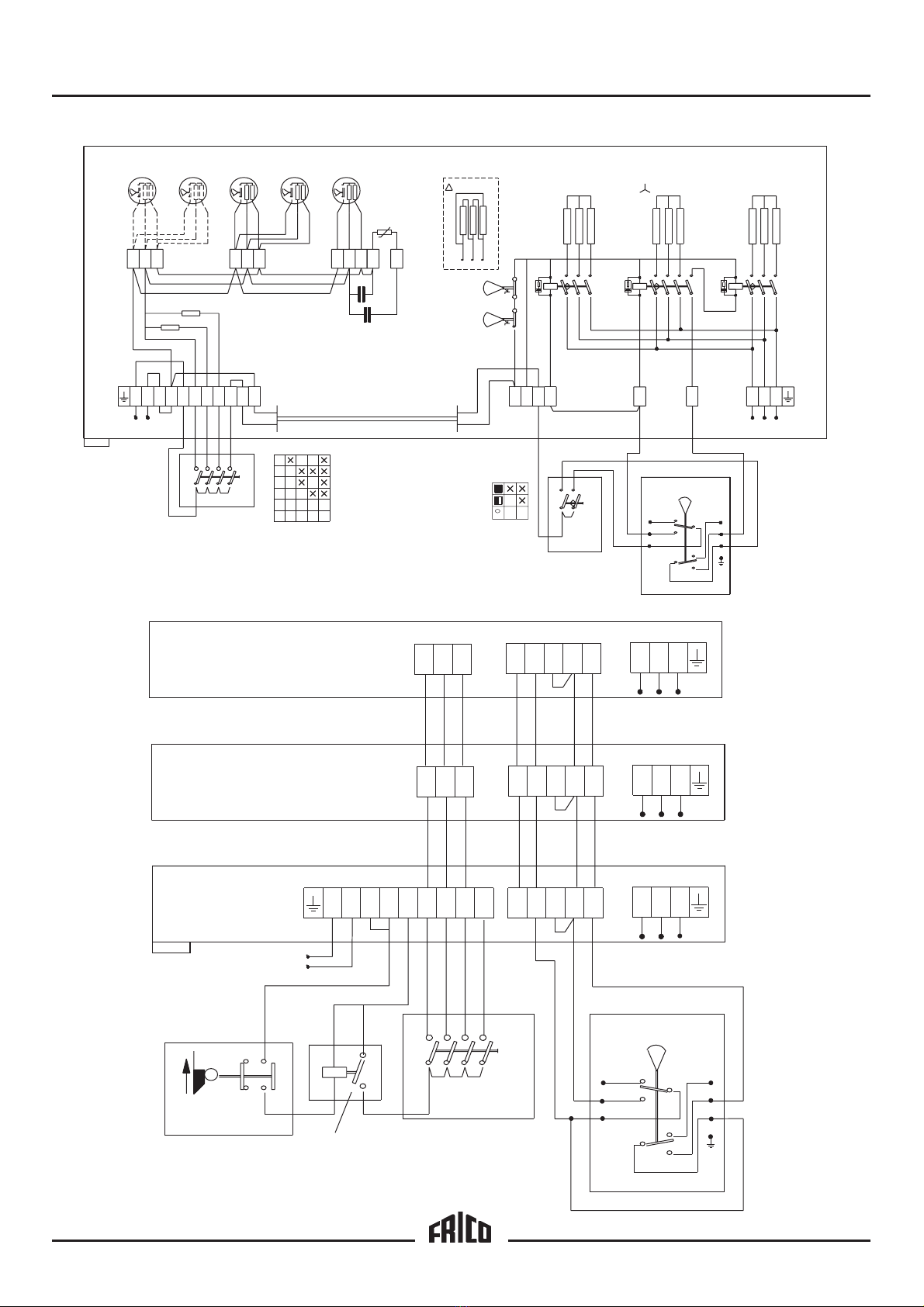
The air flow is adjusted with a selector
(ACR304 eller ACR3042) to provide maxi-
mum protection to the opening.
Units with electric heat can be regulated
with the output selector EV300 in 3 stages
(0 - 1/2 - 1/1) and with a 2-stage thermostat,
KRT 2800.
NOTE! Air pressure imbalance between
rooms separated by air curtains, considerably
reduces the efficiency of the air curtain. The
ventilation should therefore be balanced!
Mounting
a) Above the doorway
• The unit is usually mounted inside the
doorway as close to the opening as
possible with the nozzle closest to the
opening.
• When used above interior freezer doors,
the unit should be mounted on the warm
side.
• To minimize air leakage between the units,
they should be mounted close to each
other. To reach the wall mounting
screws, a min gap of 50 mm between the
units is required.
• Attach the two (2) wall mounting brackets
securely to the wall or other suitable
structure. Attach the air curtain to the
brackets (Fig.1). The units are secured with
M10-screws in the centre hole of each
bracket and in one of the notches, thus
allowing the whole unit to be turned and
the angle of the air stream to be adjusted.
• Observe the minimum distances given in
fig.3 and also that the units may not be
mounted directly below a power outlet.
b) Under a roll-up door
The air curtains are installed on two
susepension beams (50x100mm) inside the
door. The ends of the beam rest on brackets
or consoles contstructed on-site. An adaption
set is available as an accessory, AXT401/
402, which takes the door´s folding radius
into account and positions the outlet
terminals close to the opening. The adaption
set is installed as set out in fig. 4 on page 2.
• The grille on the outlet terminal, which is
secured by two screws at each end, is
dismantled and then secured to the
adaption set.
• The front long side, which is secured using
four screws at each end, is dismantled and
replaced by the adaption set.
• The Z-plate is mounted on the rear long
side using the supplied self-tapping screws.
There are two markings on the the long
side that show how the Z-plate should be
secured.
c) Standing at the side of the doorway
• When space above the doorway is
limited, the units can be mounted standing
beside the opening, thus creating a side-
blowing air stream (fig.4). Mounting plates
AVMP300 are mounted between the units
and between the lowest unit and the floor.
• The units are mounted vertically inside the
doorway as close to the edge of the
opening as possible with the nozzle
closest to the opening.
• The mounting plate consists of two parts.
The outer one is secured to the floor (or at
the top of the lower unit) with the supplied
screws. The units are secured with M10-
screws in the centre hole of each bracket
and in one of the notches, thus allowing
the whole unit to be turned and the angle
of the air stream to be adjusted. The inner
part is mounted on the under side of the
unit that is standing on the floor. The plate
Installation and Operating Instructions
GB
20

Thermozone AC 400
is secured with 3 M10-screws in the
prepared screw holes.
• Lift the unit onto the plate and screw the
plates together. Maximum building height
for vertical units is 3.5 metres.
• At the end of the uppermost unit, one of
the supplied mounting consoles (or other
suitable strut) is mounted and then
attached to the wall in order to secure the
top of the tower.
• We recommend that the collision
barrier AXP300 is mounted to prevent
the units from being hit by trucks and
other vehicles.
• Mount the air flow selector ACR304 or
ACR3042 within easy reach for
controlling the air curtains.
• To control units with electric heat, the
output selector EV300 is mounted in
conjunction with the speed selector and a
thermostat (e.g. KRT2800), in such a
place that changes to the temperature
close to the opening quickly can be
detected.
• When mounting vertically, draught can
occur due to rotating air. The mounting of
a narrow wall at the side of the opening
(the side where no units are mounted),
can decrease the rotation.
On delivery, the inlet air grille is found on the
top side of the unit. By loosening the screws
on either side of the unit, the inlet air section
may be turned around so that the inlet air
grille instead points downwards.
Electrical installation
The electrical installation should be carried
out by a qualified electrician in conformity
with prevailing regulations. The appliance
should be preceded by a triple pole switch
with at least 3 mm breaking gap.
Different alternatives for air flow
regulation are possible, see wiring diagram
pages 4–7.
The hatch on the underside of the unit is
opened by turning the locking pins 1/4 of a
lap. The connection should be made with a
cable type S05VV-U, A05VV-R or similar.
On the upper side of the unit there are
knock-outs, 2 pcs ø 29 and 4 pcs ø 23. The
cable-glands used must guarantee the
protection class requirements!
Type Power Voltage Min. area
kW V mm2
All control 230V 1,5
AC 412 12 230V 3~ 10
AC 412 12 400V 3~ 4
AC 418 18 230V 3~ 16
AC 418 18 400V 3~ 10
For the units with electrical heating, the
power and voltage should be supplied in
different connection areas (see wiring
diagram).
In the distribution board it is to be
indicated that ”The air curtains can be
supplied from more than one connection”.
Adjusting the unit and the air stream
Direction and speed of the air stream should
be adjusted with regard to the load on the
door. Pressure forces the air stream to bend
towards the interior of the room (when the
room is heated and the outside is cold). To
withstand the load, the air stream should be
directed outwards. An angel up to 15° can
be recommended. The more load caused by
negativ pressure, temperature differences
and wind, the more should the air stream be
directed outwards.
A baffle on each side of the doorway will
improve the efficiency of the air curtains.
When used above freezer or cooler doors,
the units should be mounted on the warm
side with the air stream directed 0–10°
towards the warm side.
Basic air flow settings
The air flow is set with the air flow selector
so that the speed of the air is 3–4 m/s 1 m
above the floor. The direction of the air
stream and the air speed may need to be
adjusted more exactly depending on the
load on the door.
Trouble shooting
If the fans stand still, check the following:
a) Power supply; check fuses, circuit-breaker,
time switch (if any) that starts and stops
the unit.
b) That the air flow selector is correctly set.
c) That the position limit switch is working
(if any).
If the error cannot be fixed, please contact
qualified service technician.
GB
21

Thermozone AC 400
If there is no heat, check the following:
a) Power supply to electric heater; check
fuses and circuit-breaker (if any).
b) Thermostat settings and actual
temperature.
c) That the output selector (if any) is set
correctly.
d) That the overheat protection has not
been released. If so, please check
description on next page.
Overheating
(applies to units with electric heat)
The Thermozone is equipped with an
overheat protector. If it is released due to
overheating, reset as follows:
a) Disconnect the electricity with the fully
isolated switch.
b) Investigate the matter and repair the
fault.
c) Reset is performed as follows:
• Dismount the service hatch on the
underside of the unit.
• Locate the red buttons.
• Press the buttons until a click is heard
(you do not have to press them
simultaneously).
d) Connect the Thermozone again.
If the error cannot be fixed, please contact a
qualified service technician.
Security
• Ensure that the area around the intake and
exhaust grille is kept free from material
which could prevent the air to flow through
the unit!
• During operation the surfaces of the unit
are hot!
• The unit must not be covered fully or
partially with clothes, or similar materials,
as overheating can result in fire risk!
Maintenance
NOTE! Disconnect electricity prior to cleaning
or inspection (units with electric heat can be
supplied from more than one connection).
The fan motors and the other components
require no maintenance other than cleaning
when necessary, however at least once year.
Grille, impeller and elements are vacuum
cleaned or dried clean with a damp cloth.
Open the inspection hatch to reach elements
and impellers.
GB
22
Safety cut-out
(applies to units with electric heat)
If the installation is protected by means of a
safety cut-out, which trips when the
appliance is connected, this may be due to
moisture in the heating element. When an
appliance containing a heater element, has
not been used for a long period and is stored
in a damp environment, moisture can enter
the element. This should not be seen as a
fault, but is simply rectified by connecting
the appliance to the mains supply via a
socket without a safety cut-out, so that the
moisture can be driven out of the element.
The drying time can vary from a few hours
to a few days. As a preventive measure the
Thermozone should occasionally be run for
a short time when it is not being used for an
extended period of time.
The garantee is only valid if the
Thermozone units are used in the
manner intended by the manufacturer
and in accordance with the installation
and maintenance instructions.
Manufacturer
Our products are manufatured in accordance
with applicable international standards and
regulations.
Frico AB
Box 102
SE-433 22 PARTILLE
SWEDEN
The manufacturer hereby declares that the
following products
AC401, AC402, AC412, AC418,
comply with the following EC-directives.
EC Declaration of Conformity
Defined by the EC Low Voltage Directive
73/23/EEC.
The following harmonised standards are in
use:
SS-EN 60 335-1: 1988, A2, A5, A6,
A51- A54, A56
SS-EN 60 335-2-30: 1992, A51, A52

Thermozone AC 400
Type AC401 AC402 AC412 AC418
Power [kW] 0,6 1,0 12 18
Voltage, motor / manouvre [V] 230~ 230~ 230~ 230~
Voltage, heat output [V] - - 400V3~ 400V3~
Voltage, motor / manouvre [A] 2,6 4,3 2,5 4,3
Amperage heat output [A] - - 17,3 26,0
Air flow [m3/h] 1350 / 2700 2250 / 4500 1350 / 2700 2250 / 4500
Temperature rise of passing
air at full output [°C] - - 27 / 13 27 / 13
Sound level [dB(A)] 44 / 62 45 / 63 44 / 62 45 / 63
Weight [kg] 44 71 54 86
Length [mm] 1000 1670 1000 1670
Protection class IP 24 IP 24 IP 24 IP 24
Accessories Type Measures (BxLxD)
Air flow selector (4-step)*1ACR 304 80x100x90 mm
Air flow selector high/low *1ACR 3042 150x200x105 mm
Air flow regulator (stepless), AC 401-402 *22221AG 85x170x63 mm
Output selector (0 – 1/2– 1/1) EV 300 80x100x90 mm
Position limit switch AGB 304
2-step thermostat KRT 2800 60x165x60 mm
Mounting plate for vertical mounting AVMP 300
Adaption set for ceiling mounted sliding doors AXT401
Adaption set for ceiling mounted sliding doors AXT402
False ceiling grille (1192 x 192) 22003
False ceiling grille (1515 x 192) 22004
*1 Regulation for a max of 3 units
*2 Regulation for a max of 1 units (2xAC401)
23
GB
Complete technical documentation is
available.
EC Declaration of Conformity
Defined by the EC Electromagnetic
Compatibility Directive 89/336/EC och
92/31/EC.
The following harmonised standards are in
use:
SS-EN 50 082-1: 1992
SS-EN 60 555-2/3: 1991
Complete technical documentation is
available.
Partille, 19 januari 1998
Mats Careborg
Technical Manager

Thermozone AC 400
Main office
FRICO AB Tel: +46 (0)31 336 86 00
Box 102 Fax: +46 (0)31 26 28 25
SWEDEN http://www.frico.se
Norway
FRICO AS
Postboks 82, Alnabru Tel: +47 (0)2 272 38 44
N-0614 Oslo Fax: +47 (0)2 272 38 39
http://www.frico.no
France
FRICO FRANCE Tel: +33 (0) 4 72 42 99 42
7, rue de la libération Fax: +33 (0) 4 72 42 99 49
FRANCE
Russia
FRICO representative office in Russia
1 st Golutvinsky per., 3 Tel/Fax: +7 095 238 63 20
RUSSIA
Artnr: 201210 (F89237)
00-05-19
For latest updated information, see www.frico.se
Other Frico Heater manuals

Frico
Frico PFSE4 User manual

Frico
Frico Thermozone ADR300W Series User manual

Frico
Frico Tiger P203 User manual

Frico
Frico AGS5000 User manual

Frico
Frico Elektra V User manual

Frico
Frico Pamir 3500 User manual

Frico
Frico PA1508 User manual

Frico
Frico SIReBX User manual

Frico
Frico SWH Series User manual

Frico
Frico AGS5500 User manual

Frico
Frico SE305N User manual

Frico
Frico Infralu IHAL Series User manual

Frico
Frico CIR105 User manual

Frico
Frico SWL Series User manual

Frico
Frico Thermozone ADR 200 E User manual

Frico
Frico SWT02 User manual

Frico
Frico SIReFAEMX User manual

Frico
Frico AREC3200C User manual

Frico
Frico Thermozone AD 400 W Series User manual

Frico
Frico AR3520E18 User manual