With the FrSky ACCESS protocol, the transmitter/transmitter module can bind receiver without using the "F/S" button.
Follow the step below to finish the Registration & binding procedure:
1. Put the transmitter/transmitter module into [Reg] status.
1.1 For Taranis X9D Plus 2019 as an example, turn on the transmitter, go to the MENU-MODEL SETUP-PAGE 2,choose External
RF-Mode R9M ACCESS, then select [Register].
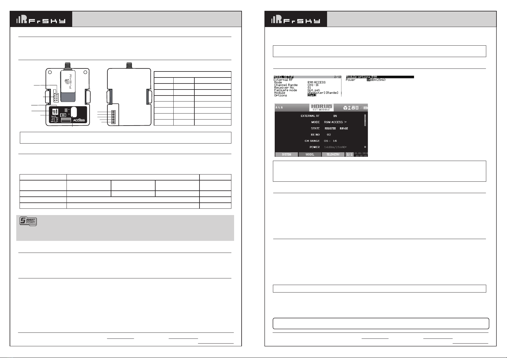
1.2 For Horus X10 Express as an example, turn on the transmitter, go to the MODEL- EXT MODULE, Turn on the EXTERNAL RF,
choose MODE [R9M ACCESS], then select STATE [REGISTER].
2. Connect the battery to the receiver while holding the F/S button on the receiver. The RED LED and GREEN LED on the receiver will
be on, indicating into the [Reg] status. Select [ENTER] on the transmitter, The RED LED and GREEN LED on the receiver will flash,
and the transmitter displays [Registration ok].
3. Turn off the receiver.
4. Move the cursor to select the receiver 1 [Bind].
Registration & Automatic binding (Smart Match )
A pre-flight range check should be done before each flying session. Reflections from nearby metal fences, concrete buildings or trees
can cause loss of signal both during range check and during the flight. Normally,the RSSI is about 45-50 at 150m in range check
mode.
1. Place the model at least 60cm (two feet) above non-metal contaminated ground (e.g on a wooden bench). The receiver antenna
should be in vertical position.
2. For Taranis X9D Plus 2019 as an example, turn on the transmitter and the receiver, go to: MODEL/SETUP/External RF Mode R9M
ACCESS/Range.
3. For Horus X10 Express as an example, turn on the transmitter and the receiver, go to: MDL/RF SYSTEM/External RF (ON)/STATE
(RANGE).
Range Check
Add:F-4,Building
C,
Zhongxiu
Technology
Park,
No.3
Yuanxi
Road,
Wuxi,
214125,
Jiangsu,
China
Technical
Support:
[email protected] Instruction Manual for FrSky R9M 2019 ( LBT ) Module Instruction Manual for FrSky R9M 2019 ( LBT ) Module
Thank you for purchasing FrSky R9M 2019 telemetry module. As Frsky long range system works in 868MHz, it offers two modes
by way of adapting to different flight situations. In order to fully enjoy the benefits of this system, please read the instruction manual
carefully and set up the device as described below.
Introduction
about the output power and operating current :
LBT Version Range Check
Operating voltage/current
Numbers of channel 16CH /
Compatibility R9 ACCESS series and TD series /
RF Power 25mW 500mW 200mW 0.001mW
7.2V@140mA 7.2V@400mA 7.2V@325mA 7.2V@50mA
Smart Port (S. Port) is a signal wire full duplex digital transmission interface developed by FrSky Electronic Co., Ltd. All
products enabled with Smart Port (including XJT module, RX8R receiver, new hub-less sensors, new Smart Dashboard, etc), serial
port user data and other user input/output devices can be connected without limitations for numbers or sequences at a high transmis
sion speed.
• Vin Voltage Range: DC 6.5V~13V
• External Power Supply: DC 6.5V~13V
• Telemetry Interface: Smart Port
Specifications
• Upgrade Interface: Smart Port
• ACCESS Protocol
• RF Operating Frequency: 868MHz
• Long range, low latency and high precision RC system
• Telemetry (25mW) /No Telemetry (500mW/200mW) mode
• Smart Port enabled and support telemetry data transmission
Features
Add:F-4,Building
C,
Zhongxiu
Technology
Park,
No.3
Yuanxi
Road,
Wuxi,
214125,
Jiangsu,
China
Technical
Support:
[email protected] 5. Connect the battery to the receiver, the GREEN LED on the receiver will be on, indicating into the [Bind] status. Select the RX, the
GREEN LED on the receiver will keep lit, the RED LED will flash, and the transmitter displays [Bind successful].
6. The transmitter exit [Bind], the receiver GREEN LED will flash, RED LED will be off, indicating working normally.
Note: After binding procedure is completed, resupply the power and check if the receiver is truly communicating with
the transmitter.
More information please refer to the introduction manual for transmitter.
Note: If failsafe is not set, the model will hold the last position after signal is lost, thus it may fly away or cause injury.
There are 3 failsafe modes: No Pulse, Hold, Custom
• No Pulse: on loss of signal the receiver produces no pulses on any channel. To use this type, select it in the menu and wait 9 seconds
for the failsafe to take effect.
• Hold: the model will maintain the last position after the signal is lost. To use this type, select it in the menu and wait 9 seconds for
the failsafe to take effect.
• Custom: the customized position of each individual channel. The model will move to the pre-set position after the signal is lost. Move
the cursor to “Set” and press ENTER, you will see FAILSAFE SETTING screen below. Move the cursor to the channel you want to
set failsafe on, and press ENTER. When moving the crresponding sticks or switches, you will see the channel bar moving. Move the
channel bar to the place you want for failsafe and long press ENTER to finish the setting. Wait 9 seconds before the failsafe takes
effect.
How to Set Failsafe mode (on the transmitter)
FrSky is continuously adding features and improvements to our products. To get the most from your product, please check
the download section of the FrSky website www.frsky-rc.com for the latest update firmware and manuals
How to switch Telemetry (25mW) or No Telemetry (500mW/200mW)
-- For Taranis Series transmitters, turn on the transmitter, go to the MENU-MODEL SETUP-PAGE2. Select the RF Power.
-- For Horus Series transmitters, turn on the transmitter, go to the MODEL and choose the EXT MODULE, Select the Power.
Note:
1. The 2 modes both conform to the CE standard.
2. The receiver should be rebound after switching the modes between Telemetry (25mW) and No Telemetry (200mW/
500mW).
External
Power
6.5V~13V
R9M
20
19
LONG RANGE
Smart Port
RS232 Serial Port
Function Button
Switch 2
Switch 1
RX
TX
Vin
GND
S.Port
External Power Supply Port
ON
1 2
F/S
Overview
LED Indication
On
Off
Flash
Flash
On
On
On
RED LED
Flash
Off
Off
On
Flash
On
Off
Green LED
Register
Register successfully
Bind
Bind successfully
Range
Tele
Non-Tele
Status
* If the module is connected to both an external power and a transmitter, it will automatically be powered by the one
with highervoltage.


