LEDS
SYS
FAN
Status Description
PWR
ETH
SFP+
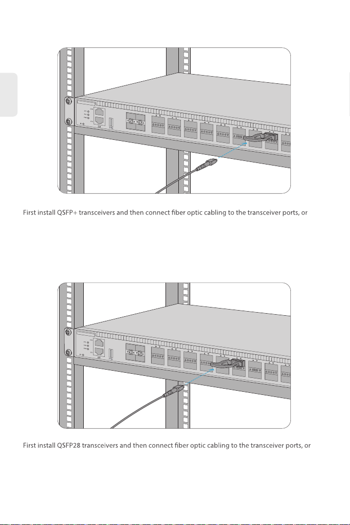
QSFP+
QSFP28
Green
Blinking Green Quickly (2Hz)
Blinking Green Slowly (0.5Hz)
Amber
Blinking Amber Quickly (2Hz)
Blinking Amber Slowly (0.5Hz)
System is abnormal.
System is running in u-boot mode.
System is normally running.
System occurs alarm or error.
System is initial in u-boot mode.
System software is in initial state.
No power or no system runs or runs abnormally.
Green
Amber
Green
Amber
FAN module is normally running.
FAN module occurs error.
Power supply is absent.
Power supply is OK.
Power supply is abnormal.
Power supply is absent or single power supply is
abnormal.
Green
Blinking Green
Green
Blinking Green
Green
Blinking Green
Green
Blinking Green
Port is linked.
Port is receiving or transmitting packets.
Port is not linked.
10G port is linked.
10G packets are receiving or transmitting.
Port is not linked.
40G port is linked.
40G packets are receiving or transmitting.
Port is not linked.
100G port is linked.
100G packets are receiving or transmitting.
Port is not linked.
3
EN