22 23 24 25 26 27 28 29 30 31 32 33 34 35 36 37 38 39 40 41 42 43 44 45 46 47 48 49 50 51 52
10G
1G
35 36 37 38 39 40 41 42 43 44 45 46 47 48 49 50 51 52
10G
Conguring the Switch
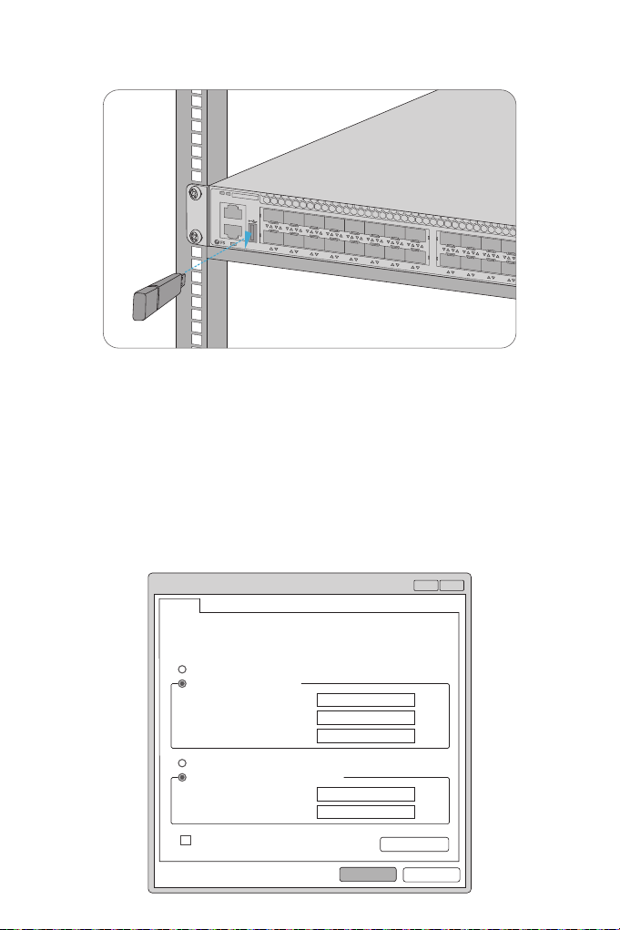
Insert the Universal Serial Bus (USB) ash disk to the USB port for software and conguration backup
and oine software upgrade.
Step 1: Connect the computer to any Ethernet port of the switch using the network cable.
Step 2: Set the IP address of the computer to 192.168.1.x. ("x" is any number from 2 to 254.). Set the
subnet mask of the computer to 255.255.255.0.
Connecting the USB Port
Conguring the Switch Using the Web-based Interface
CON
ETH
ID SYS
1 2 3 4 5 6 7 8 9 10 11 12 13 14 15 16
17 18 19 20 21 22 23 24 25 26 27 28 29
1G
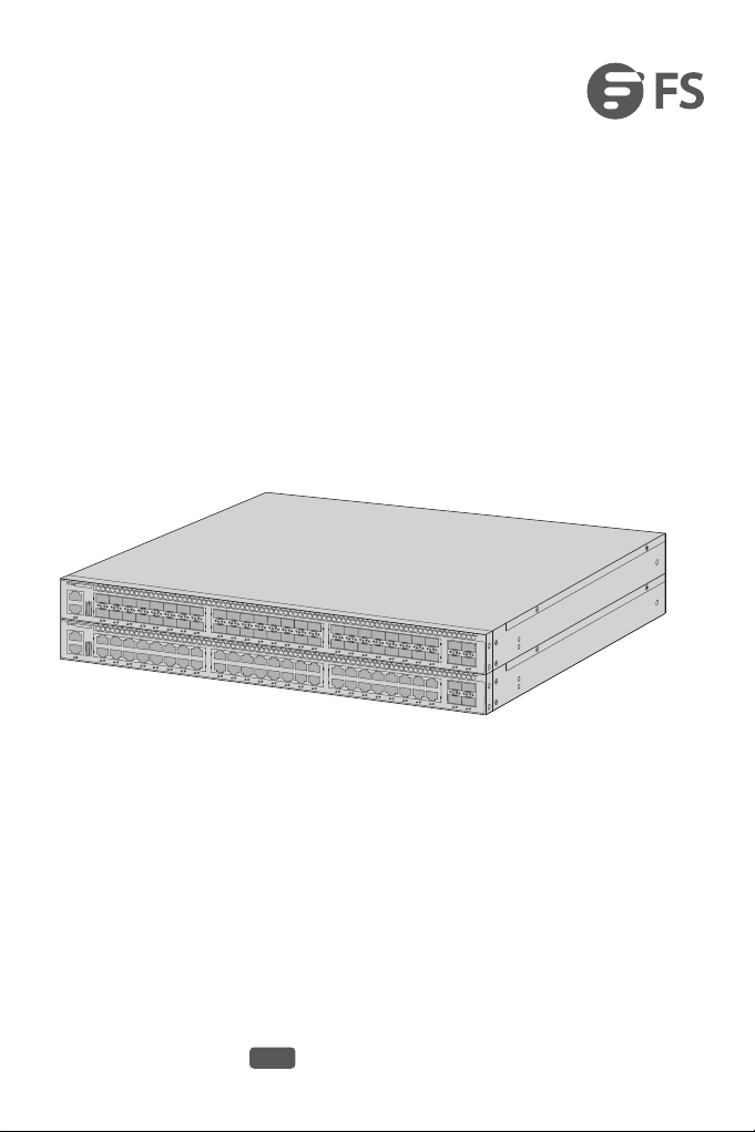
S5800-48F4SR
USB
?x
OK Cancel
General
IP address:
Subnet mask:
Default gateway:
You can get IP settings assigned automatically if your network
supports this capability. Otherwise, you need to ask your network
administrator for the appropriate IP settings.
Internet Protocol Version 4(TCP/IPv4) Properties
Use the following IP address:
Obtain an IP address automatically
Preferred DNS server:
Alternate DNS server:
Validate settings upon exit Advanced...
. . . 21168192
0255
255255
. . .
. . .
. . .
. . .
Obtain DNS server address automatically
Use the following DNS server addresses: