FS S3700-24T4F User manual

COMMUTATEUR D'ACCÈS FULL-GIGABIT
S3700-24T4F Switch
FULLGIGABIT ACCESS SWITCH
V3.1
Quick Start Guide
Quick-Start Anleitung
Guide de Démarrage Rapide

EN
Introduction
Thank you for choosing FS S3700-24T4F Full-gigabit Access Switch. This guide is designed to familiarize
you with the layout of the switch and describes how to deploy the switch in your network.
S3700-24T4F
Accessories
Power Cord x 1 Console Cable x 1 Mounting Bracket x 2
Rubber Pad x 4 M3 Screw x 8
1
Grounding Cable x 1

EN
Hardware Overview
Front Panel Ports
Front Panel Button
RJ45
RESET
Console SFP
Ports Description
RJ45 10/100/1000BASE-T ports for Ethernet connection
Hot swappable SFP ports for 1G fiber connection
An RJ45 console port for serial management
SFP
Console
Reset Keep the device powered on, press the button "RESET" for 6 seconds,
and the system will return to the default setting.
Button Description
2

EN
Site Environment
Front Panel LEDs
Back Panel
Grounding Point
Power Supply
SYS
SFPPWR RJ45
Do not operate it in an area that exceeds an ambient temperature of 50°C.
The installation site must be well ventilated. Ensure that there is adequate air flow around the
switch.
Be sure that the switch is level and stable to avoid any hazardous conditions.
Do not install the equipment in a dusty environment.
The installation site must be free from leaking or dripping water, heavy dew, and humidity.
LEDs Status Description
PWR Green Switch is powered on.
SYS
Orange 10/100M connection.
1000M connection.Green
Off
Green
Off No signal transmission.
1000M connection.
No signal transmission.
Blinking Green System is working properly.
RJ45
SFP
3

EN
Installing
Desk Mounting
Rack Mounting
1. Secure the mounting brackets to the two sides of the switch with eight M3 screws.
1. Attach four rubber pads to the bottom.
2. Place the chassis on a desk.
4

EN
Grounding the Switch
2. Attach the switch to the rack using four M6 screws and cage nuts.
1. Connect one end of the grounding cable to a proper earth ground, such as the rack in which the
switch is mounted.
2. Secure the grounding lug to the grounding point on the switch back panel with the washers
and screws.
CAUTION: The earth connection must not be removed unless all supply connections have
been disconnected.
5

EN
Connecting to the power
Connecting to the RJ45 Ports
1. Plug the AC power cord into the power port on the back of the switch.
2. Connect the other end of the power cord to an AC power source.
1. Connect an Ethernet cable to the RJ45 port of a computer, printer, network storage, or other network
devices.
2. Connect the other end of the Ethernet cable to the RJ45 port of the switch.
WARNING: Do not install power cables while the power is on.
6

EN
Connecting to the SFP Ports
Connecting to the Console Port
1. Plug the compatible SFP transceiver into the SFP port.
2. Connect a fiber optic cable to the fiber transceivers. Then connect the other end of the cable to
another fiber device.
1. Connect the DB9 female connector of the console cable to RS-232 serial port on the computer.
2. Insert the RJ45 connector into the RJ45 console port on the front of the switch.
7

EN
Configuring the Switch
Troubleshooting
Configuring the Switch Using the Web-based lnterface
Configuring the Switch Using the Console Port
Power LED Working Abnormally
Step 1: Connect your computer to any Ethernet port of the switch using the network cable.
Step 2: Set up the lP configuration on your computer.The lP address of your computer should be set in
the same subnet addresses of the switch.The lP address is 192.168.1.x("x" is any number from
2 to 254).
Step 3: Open a web browser window.Enter the default lP address of the switch http://192.168.1.1 in the
address bar and press Enter.
Step 4: When the login page appears choose the language that you prefer and enter the username and
password.
The default username is admin.The default password is admin.
Step 5: Click Sign in to display the web-based configuration page.
Step 1:Connect a computer to the switch's console port using the supplied console cable.
Step 2:Start the terminal simulation software such as HyperTerminal on the computer.
Step 3:Configure the terminal simulation with the following parameters:
115200 bits per second
8 data bits
no parity
1 stop bit
no flow control
Step 4:Enter the username and password.The default username is admin.The default password is
admin.
1. Check the power cable connections at the switch and the power source.
2. Make sure the power cord used matches the voltage and frequency of your local power.
8

EN
HyperTerminal Displaying Abnormally
Accessing the Web-based Configuration Page Unsuccessfully
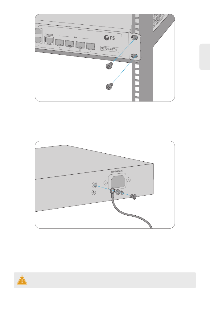
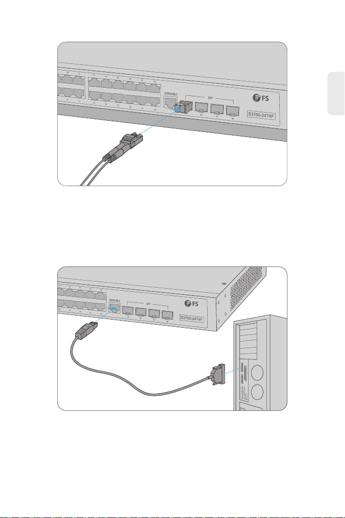
1. Make sure the power supply is normal and the console cable is properly connected.
2. Check if the console cable is the right type.
3. Check if the control cable driver is properly installed on the computer.
4. Ensure the parameters of the HyperTerminal are correct.
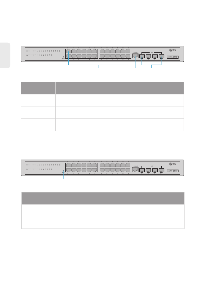
1. Check every port LED on the switch and make sure the Ethernet cable is connected properly.
2. Try another port on the switch and make sure the Ethernet cable is suitable and works normally.
3. Power off the switch. After a while, power it on again.
4. Make sure the IP address of your PC is set within the subnet of the switch.
5. If you still cannot access the configuration page, please restore the switch to its factory defaults.
Then the IP address of your PC should be set as 192.168.1.x ("x" is any number from 2 to 254) and
Subnet Mask as 255.255.255.0.
Online Resources
Download
Help Center
Contact Us
https://www.fs.com/products_support.html
https://www.fs.com/service/fs_support.html
https://www.fs.com/contact _us.html
Product Warranty
FS ensures our customers that any damage or faulty items due to our workmanship, we will offer a
free return within 30 Days from the day you receive your goods. This excludes any custom made
items or tailored solutions.
Warranty: FS S3700-24T4F Switch enjoys 4 years limited warranty againist defect in
materials or workmanship. For more details about warranty, please check at
https://www.fs.com/policies/warranty.html
Return: If you want to return item(s), information on how to return can be found at
https://www.fs.com/policies/day_ return_ policy.html
4
9

Einführung
Vielen Dank, dass Sie sich für den FS S3700-24T4F Full-Gigabit Access Switch entschieden haben. Diese
Anleitung soll Sie mit dem Aufbau des Switches vertraut machen und beschreibt, wie Sie den Switch in
Ihrem Netzwerk einsetzen.
S3700-24T4F
Zubehör
Netzkabel x 1 Konsolenkabel x 1 Montagehalterung x 2
Gummipad x 4 M3-Schraube x 8
10
DE
Erdungskabel x 1

Hardware-Übersicht
Ports an der Vorderseite
Taste an der Vorderseite
RJ45
RESET
Console SFP
Ports Beschreibung
RJ45 10/100/1000BASE-T-Ports für Ethernet-Anschluss
Hot-Swap-fähige SFP-Ports für 1G-Glasfaseranschluss
RJ45-Konsolenport für die serielle Verwaltung
SFP
Console
Reset Halten Sie das Gerät eingeschaltet und drücken Sie die Taste "RESET" für
6 Sekunden, um das System auf die Standardeinstellung zurückzusetzen.
Taste Beschreibung
11
DE

Standortumgebung
LEDs an der Vorderseite
Rückseite
Erdungspunkt
Stromversorgung
SYS
SFPPWR RJ45
Betreiben Sie es nicht in einem Bereich, der eine Umgebungstemperatur von 50 °C überschreitet.
Der Installationsort muss gut belüftet sein. Stellen Sie sicher, dass ein ausreichender Luftstrom um
den Switch herum vorhanden ist.
Stellen Sie sicher, dass der Switch eben und stabil steht, um gefährliche Bedingungen zu vermeiden.
Installieren Sie das Gerät nicht in einer staubigen Umgebung.
Der Installationsort muss frei von austretendem oder tropfendem Wasser, starkem Tau und
Feuchtigkeit sein.
LEDs Status Beschreibung
PWR Grün Der Switch ist eingeschaltet.
SYS
Orange 10/100M-Verbindung.
1000M-Verbindung.Grün
Aus
Grün
Aus Keine Signalübertragung.
1000M-Verbindung.
Keine Signalübertragung.
Grün blinkend Das System arbeitet ordnungsgemäß.
RJ45
SFP
12
DE

Installation
Montage auf einem Tisch
Montage im Rack
1. Befestigen Sie die Montagehalterungen mit acht M3-Schrauben an den beiden Seiten des Switches.
1. Bringen Sie vier Gummipads an der Unterseite an.
2. Stellen Sie das Gehäuse auf einen Tisch.
13
DE

Erdung des Switches
2. Befestigen Sie den Switch mit vier M6-Schrauben und Käfigmuttern am Rack.
1. Schließen Sie ein Ende des Erdungskabels an eine geeignete Erdung an, z. B. an das Rack, in dem
der Switch montiert ist.
2. Befestigen Sie die Erdungslasche mit den Unterlegscheiben und Schrauben am Erdungspunkt an
der Rückwand des Switches.
ACHTUNG: Die Erdungsverbindung darf erst dann entfernt werden, wenn alle
Versorgungsanschlüsse getrennt wurden.
14
DE

Anschluss an das Stromnetz
Anschluss der RJ45-Ports
1. Stecken Sie das Netzkabel in den Netzanschluss auf der Rückseite des Switches.
2. Schließen Sie das andere Ende des Netzkabels an eine Netzstromquelle an.
1. Schließen Sie ein Ethernet-Kabel an den RJ45-Anschluss eines Computers, Druckers,
Netzwerkspeichers oder anderer Netzwerkgeräte an.
2. Schließen Sie das andere Ende des Ethernet-Kabels an den RJ45-Port des Switches an.
WARNUNG: Installieren Sie keine Netzkabel, während das Gerät eingeschaltet ist.
15
DE

Anschluss der SFP-Ports
Anschluss der Konsolenports
1. Stecken Sie den kompatiblen SFP-Transceiver in den SFP-Port.
2. Schließen Sie ein Glasfaserkabel an die Glasfasertransceiver an. Schließen Sie dann das andere Ende
des Kabels an ein anderes Glasfasergerät an.
1. Verbinden Sie die DB9-Buchse des Konsolenkabels mit der seriellen RS-232-Schnittstelle des Computers.
2. Stecken Sie den RJ45-Stecker in den RJ45-Konsolenanschluss an der Vorderseite des Switches.
16
DE

Konfiguration des Switches
Fehlerbehebung
Konfiguration des Switches über die webbasierte Schnittstelle
Konfiguration des Switches über den Konsolenanschluss
Power LED arbeitet nicht ordnungsgemäß
Schritt 1: Schließen Sie Ihren Computer über das Netzwerkkabel an einen beliebigen Ethernet-Anschluss
des Switches an.
Schritt 2: Richten Sie die lP-Konfiguration auf Ihrem Computer ein. Die lP-Adresse Ihres Computers
sollte in der gleichen Subnetzadresse des Switches liegen. Die lP-Adresse ist
192.168.1.x ("x" ist eine beliebige Zahl von2 bis 254).
Schritt 3: Öffnen Sie ein Webbrowser-Fenster, geben Sie die Standard-LP-Adresse des Switches
http://192.168.1.1 in die Adressleiste ein und drücken Sie die Eingabetaste.
Schritt 4: Wenn die Anmeldeseite erscheint, wählen Sie die gewünschte Sprache und geben Sie den
Benutzernamen und das Passwort ein.
Der Standard-Benutzername ist admin. Das Standard-Passwort ist admin.
Schritt 5: Klicken Sie auf Sign in, um die webbasierte Konfigurationsseite anzuzeigen.
Schritt 1: Schließen Sie einen Computer über das mitgelieferte Konsolenkabel an den Konsolenanschluss
des Switches an.
Schritt 2: Starten Sie die Terminalsimulationssoftware, z. B. HyperTerminal, auf dem Computer.
Schritt 3: Konfigurieren Sie die Terminalsimulation mit den folgenden Parametern:
115200 Bits pro Sekunde
8 Data Bits
No Parity
1 Stop Bit
No Flow Control
Schritt 4: Geben Sie den Benutzernamen und das Passwort ein. Der Standard-Benutzername ist admin.
Das Standard-Passwort ist admin.
1. Überprüfen Sie die Stromkabelverbindungen am Switch und an der Stromquelle.
2. Vergewissern Sie sich, dass das verwendete Netzkabel mit der Spannung und Frequenz der örtlichen
Stromversorgung übereinstimmt.
17
DE

HyperTerminal wird nicht ordnungsgemäß angezeigt
Zugriff auf die webbasierte Konfigurationsseite erfolglos
1. Stellen Sie sicher, dass die Stromversorgung normal ist und das Konsolenkabel richtig angeschlossen ist.
2. Prüfen Sie, ob das Konsolenkabel der richtige Typ ist.
3. Prüfen Sie, ob der Steuerkabeltreiber richtig auf dem Computer installiert ist.
4. Stellen Sie sicher, dass die Parameter des HyperTerminals korrekt sind.
1. Überprüfen Sie jede Port-LED am Switch und stellen Sie sicher, dass das Ethernet-Kabel richtig
angeschlossen ist.
2. Versuchen Sie einen anderen Port am Switch und stellen Sie sicher, dass das Ethernet-Kabel geeignet
ist und normal funktioniert.
3. Schalten Sie den Switch aus. Schalten Sie ihn nach einer Weile wieder ein.
4. Stellen Sie sicher, dass die IP-Adresse Ihres PCs innerhalb des Subnetzes des Switches eingestellt ist.
5. Wenn Sie immer noch nicht auf die Konfigurationsseite zugreifen können, setzen Sie den Switch bitte
auf die Werkseinstellungen zurück. Dann sollte die IP-Adresse Ihres PCs auf 192.168.1.x ("x" ist eine
beliebige Zahl von 2 bis 254) und die Subnetzmaske auf 255.255.255.0 eingestellt sein.
Online Ressourcen
Download
Hilfecenter
Kontakt
https://www.fs.com/de/products_support.html
https://www.fs.com/de/service/fs_support.html
https://www.fs.com/de/contact_us.html
Produktgarantie
FS versichert seinen Kunden, dass alle Schäden oder fehlerhaften Artikel, die auf unsere Verarbeitung
zurückzuführen sind, innerhalb von 30 Tagen ab dem Tag, an dem Sie Ihre Ware erhalten haben,
kostenlos zurückgegeben werden können. Dies gilt nicht für Sonderanfertigungen oder
maßgeschneiderte Lösungen.
Warranty: Der FS S3700-24T4F Switch genießt 4 Jahre eingeschränkte Garantie auf
Material- und Verarbeitungsfehler. Weitere Details zur Garantie finden Sie unter:
https://www.fs.com/de/policies/warranty.html
Wenn Sie Artikel zurückgeben möchten, finden Sie Informationen zur Rückgabe unter:
https://www.fs.com/de/policies/day_return_policy.html
4
18
DE

Introduction
Nous vous remercions d'avoir choisi le commutateur d'accès full-gigabit FS S3700-24T4F. Ce guide est
conçu pour vous puissiez vous familiariser avec la configuration du commutateur et indique comment
procéder à son déploiement.
S3700-24T4F
Accessoires
Câble d'Alimentation x 1 Câble de Console x 1 Support de Montage x 2
Coussin en Caoutchouc x 4 Vis M3 x 8
19
FR
Câble de Mise à Terre x 1
Other manuals for S3700-24T4F
12
Table of contents
Languages:
Other FS Switch manuals

FS
FS S3700-24T4F Instruction Manual

FS
FS S3200 Series User manual

FS
FS S5900-24S4T2Q Quick guide

FS
FS S3900 Series User manual

FS
FS S3700-24T4F Instruction Manual

FS
FS S3700-24T4F Instruction Manual

FS
FS S5800-48F4SR User manual

FS
FS PoE+ Series User manual

FS
FS S5500-48T8SP Operating instructions

FS
FS S5300-12S User manual