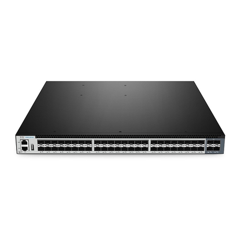
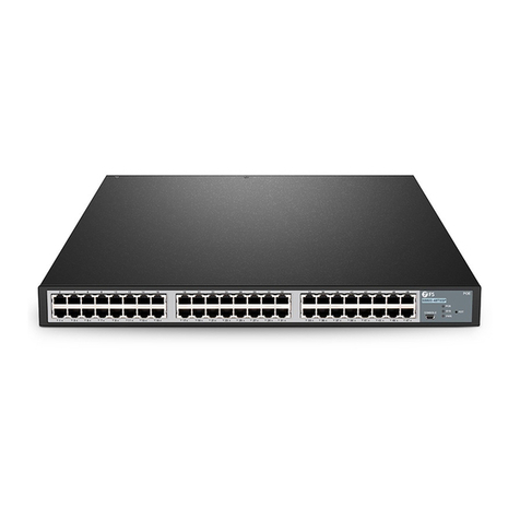
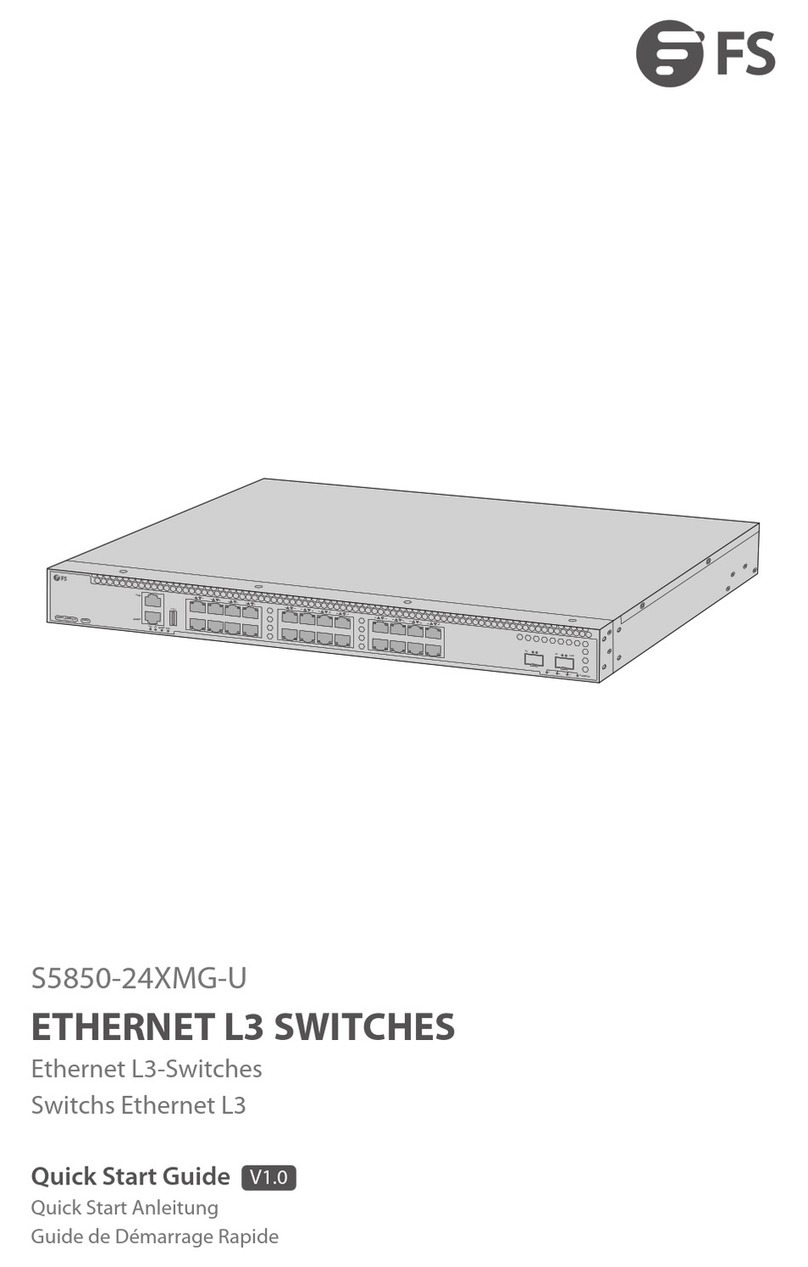
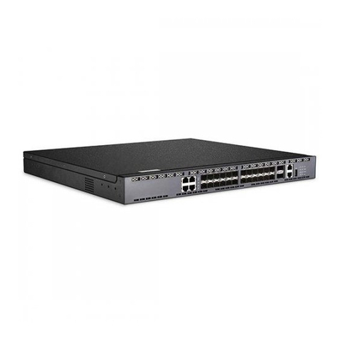
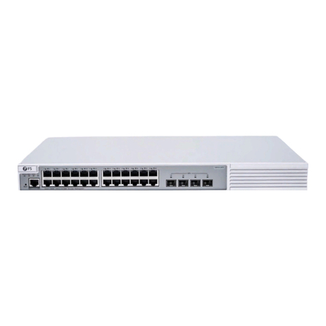
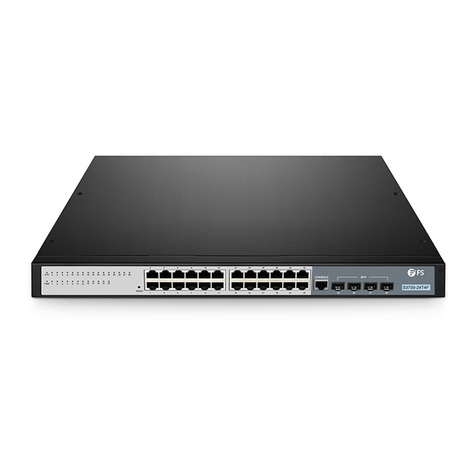
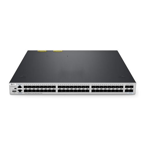
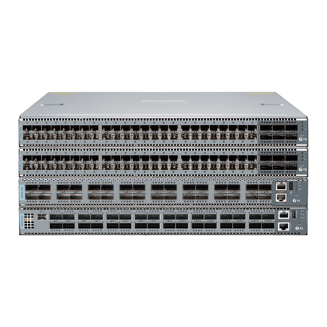
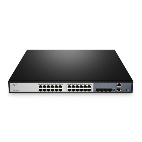
FS S3410 Series Operating manual

Innovation · Expertise · Agility
V1.0.2307A
S3410 Series
Switch Hardware Installation
and Maintenance Guide

Innovation · Expertise · Agility
Preface
1
Audience:
This document is intended for network engineers responsible for S3410
switch installation and maintenance . You should have experience in
networkdeviceinstallationandmaintenance.
Feature Statement:
Please visit the FS.COM Technical Documents page to download the
datasheet and obtain information on the specifications supported by the
product.
Safety Statement:
•To avoid harm to people and equipment, please read the safety
recommendations in the Safety Precautions for FS Switches before
installing the FS Switch.
•Verify that the requirements described in the Safety Precautions for FS
Switches have been met.

Contents
1. Hardware Installation and Parts Replacement
04
04
07
09
11
15
15
1
1.1 Installation Procedure
1.2 Installation Preparation
1.3 Installing a Switch
1.4 Installing Modules
1.5 Connecting a Switch
1.6 Post-Installation Checks
1.7 System Commissioning
1.8 Parts Replacement 8
2. Troubleshooting After Installation
2.1 Troubleshooting Flowchart 25
2

Innovation · Expertise · Agility
1
3
Hardware Installation and
Parts Replacement
S3410 series switches are a new generation of secure smart switches launched by
FS
based
on the concepts of network security and easy-to-use management.
S3410 series switches are a next-generation intelligent switch that features high
performance, high security, multiple services and ease of use to meet the needs
of the current networks. The switch can provide the complete end-to-end Quality
of Service (QoS), flexible and abundant security policies and policy-based
network management for various networks. It is greatly ideal for such applications
as campus network, enterprise network, government network, service network,
residential broadband access and business building network, providing high-speed,
high-efficiency, secure and intelligent access solutions

Innovation · Expertise · Agility 4
1.1 Installation Procedure
1.2 Installation Preparation
The S3410 switch is a relatively complex device, and the installation location, networking method, power
supply and alignment of the device should be carefully planned and arranged before installation.
Confirm the following before installation:
• The installation site provides sufficient space for heat dissipation.
• The installation site meets the temperature and humidity requirements of the switch.
• The power supply and required current are available in the installation site.
• The Ethernet cables have been deployed in the installation site.
1.2.1 Precautions for Safe Use
Hardware
Installation
and
Parts
Replacement
Switch
Hardware
Installation
and
Maintenance
Guide
Installation Preparation
Connecting a SwitchPost-Installation Checks
System Commissioning
End
Installing a Switch Installing Modules
During installation, note the following points
• 100-meter network cables should be laid inside the equipment room and outdoor cabling of such cables is
prohibited.
If outdoor cabling is necessary, take relevant measures for lightning protection
• Connect the power cables of different colors to the corresponding grounding posts.
• Ensure that the interface of the power supply cable is properly connected to the power interface of the device
The power cablesmust be protected using power cable retention clips after they are connected to the device.
• Do not place any articles on the on the switch.
• Reserve a spacing of at least 10 cm around the chassis for good ventilation. Do not stackthe devices.
• The switch should be located at places free from the large power radio launch pad, radar launch pad, and
high-frequency large-current devices. If necessary, use electromagnetic shielding. For example,use
interfac
cables to shield cables.
• 100-meter network cables should be laid inside the equipment room and outdoor cabling of such cables is
prohibited. If outdoor cabling is necessary, take relevant measures for lightning protection

Innovation · Expertise · Agility
1.2.2
Checking
the
Installation
S
ite.
S3410
switch
must
be
installed
indoors.The
installation
site
must
meet
the
following
requirements
Item Requirement
Cleanliness The
device
must
be
installed
in
a
clean,
dry,
and
well
ventilated
standard
equipment
room
with
controllable
temperature.
Dust proofing
Dustproof measures must be taken in the site. Dust will cause electrostatic discharges on the chassis and
affect connections of metal connectors and joints. This shortens service life of the device and may cause
failures of the device.
Temperature
and
humidity
The equipment room must be free from leaking or dripping water, heavy dew, and damp. The temperature
and humidity in the installation site must be within specifications. For the operating temperature and
relative humidity ranges required by the device, see the device specifications. If the relative humidity
exceeds 70%, using dehumidifiers or dehumidifying air conditioners is recommended.
Corrosive gases
avoidance The installation site must be free from acidic, alkaline, or corrosive gases.
Hardware Installation and Parts Replacement
Switch Hardware Installation and Maintenance Guide
5
1.2.3 Mounting
the
Cabinet
or
rack
S3410 switchmustbeinstalledindoors.Theinstallationsitemustmeetthefollowingrequirements
•
All
expansion
bolts
for
fastening
the
cabinet
base
to
the
ground
should
be
installed
and
tightened
in
sequence
from
bottom
to
up
(large
flat
washer
,
spring
washer
,
and
nut
),
and
the
installation
holes
on
the
base
and
the
expansion bolts
are
aligned
.
•
The
installed
cabinet
is
not
movable
after
installation.
•
The
installed
cabinet
is
vertical
to
the
ground.
•
When
multiple
cabinets
are
placed
side
by
side
in
the
equipment
room,
they
should
be
aligned
with
each
other
an
error
,leaving
less
than
5mm
(0.20
in.)
•
The
front
and
rear
doors
of
the
cabinet
should
be
installed
to
allow
you
open
and
close
them
smoothly
locks
should
work
normally,
and
all
keys
should
be
complete
.
•
There
should
be
no
unnecessary
and
informal
labels
inside
the
cabinet
and
on
service
modules .Filler
panels
are
installed
in
empty
slots
•
The
screws
in
the
cabinet
should
be
fastened
tightly
and
be
of
the
same
model.
•
The
switch
is
securely
installed,
and
the
screws
on
the
panel
should
be
fastened
tightly.
•
All
wiring
outlets
at
the
top
and
bottom
of
the
cabinet
should
be
installed
with
rodent
-resistant
nets
wit
openings
of
no
more
than
15mm
(0.59
in.)
in
diameter
to
prevent
rodents
and
other
small
animals
from
entering
the
cabinet
•
An
anti-static
wrist
strap
should
be
provided
in
the
cabinet.

Innovation · Expertise · Agility
Procedure:
1. Plan the available space before installing the cabinet. Maintain a clearance before the front and back
doors for maintenance and operation.
2. Install and fasten the cabinet in the specified site as planned.
3. Install the cable troughs and cables.
4. Install the trays and cable management brackets on the rack according to the number of switches
installed into the cabinet.
1.2.4 Checking the Power Conditions
•Before use, please check whether there is obvious damage to the power supply shell and whether the
power supply is defective such as abnormal noise.
Hardware Installation and Parts Replacement
Switch Hardware Installation and Maintenance Guide
6
• The device is only allowed to be plugged into the power module that accompanies the device, otherwise
it may lead to unknown risks.
• Power module in 1+1 backup can be hot-swapped one of them, need to ensure that the other power
module on the equipment is in the power supply state when replaced, otherwise unplugging the power
module will cause the switch to lose power, resulting in business interruption.
• Prohibit the mixed use of power modules with different power and different cooling methods.
1.2.4 Preparing Installation Tools and Accessories
Phillips
screwdriver,
Ethernet
and
optical
cables,
cage
nuts,
diagonal
pliers
and
cable
ties
Common
Tools
Special
Tools
Cleaning
Tools
Meters
Anti-static
gloves,
wire
stripper,
crimping
plier,
RJ45
connector
crimping
plier,
and
wire
cutter
Dust-free
paper
and
fiber
end-face
microscope
Multimeter,
bit
error
rate
tester
(BERT),
and
optical
power
meter
• The 3410
switch
is
delivered
without
a
tool
kit.
You
need
to
prepare
a
tool
kit
by
yourself

1.3 Installing a Switch
Precautions:
Before installing the switch in a cabinet, please check whether the racks are properly positioned. If the racks
are too close to the front door of the cabinet, you may not be able to close the front door after plugging in the
Ethernet and fiber cables . The front panel of the switch should be at least 10mm (0.39 in.) away from the
front door of the cabinet. Please confirm the following before installing the switch:
•The cabinet is secured.
•The modules in the cabinet are installed.
•There are no obstructions in and around the cabinet.
•The switch is prepared and transported to a location close to the cabinet.
Hardware Installation and Parts Replacement
Switch Hardware Installation and Maintenance Guide
1.3.1 Mounting the Switch in a Cabinet or Rack
S3200 series switches follow the EIA standard dimensions and can be installed on the 19-inch
rack,:
1. Attach
the
mounting
brackets
to
the
switch
with
the
supplied
screws,as
shown
in Figure 1
Figure 1: Mounting the Brackets
2.Use the supplied M6 screws and cagenuts to securely attach the mounting brackets to the rack, as shown
in Figure 2
Figure 2
:
Attaching
the
Brackets
to
the
Rack
2. Use the supplied M6 screws and cagenuts to securely attach the mounting brackets tthe
rack, as shown in Figure 2
7

Innovation · Expertise · Agility
1.3.2 Mounting the Switch on a Workbench
In most cases, users do not have a standard 19-inch rack. Therefore, the most common method
is to place the switch on. Although it is easy and simple, you shall pay attention to the following
:
Step1: Attach the four rubber pads to the recessed areas on the bottom of the switch,as shown
in Figure 3
Figure
3:
Desktop installation
Step2:Place the switch flat on the table to ensure that the air around the switch can flow well
Hardware Installation and Parts Replacement
Switch Hardware Installation and Maintenance Guide
1.3.3
Mounting the Switch Against a Wall
Wall Installation:
• Before
drilling
holes
on
a
wall,
ensure
that
there
is
no
circuitry,
water
pipe,
or
gas
pipeline
in
the
wall
area
to
be
drilled
to
avoid
bodily
injury. Wall Installation
• Do
not
place
any
flammable
or
explosive
objects
above
or
under
the
equipment,
and
do
not
obstruct
the
equipment
with
foreign
objects
within
a
1
m
radius.
• Ensure
that
no
holes
are
drilled
that
face
upwards
to
prevent
water
ingress
and
equipment
damage.
• Ensure
that
screws
are
securely
installed .
Otherwise ,
the
equipment
may
fall
due
to
tension
after
cable
connection,
causing
equipment
damage
or
even
bodily
injury.
• Do
not
place
the
switch
in
a
place
subject
to
vibration,
impact
and
instability,
and
do
not
place
the
switch
in
a
place
that
is
too
high,
otherwise
it
may
cause
personal
injury
or
equipment
damage.
• Pay
attention
to
the
fixation
of
the
external
cables
of
the
switch
during
installation
to
avoid
the
switch
falling
off
due
to
the
heavy
external
cables.
8

Innovation · Expertise · Agility
1.4 Installing Modules
Hardware Installation and Parts Replacement
Switch Hardware Installation and Maintenance Guide
1.4.1
Installing
pluggable
Power
Module
•Wear an anti-static wrist strap before the following operations.
1. Remove
the
new
power
module
from
its
packing
materials
and
make
sure
the
input
specifications
meet
requirements.
2.
Take
a
fan
module
from
its
packing
materialsGrasp
the
handle
and
slide
the
module
into
the
slot
along
the
guide
rail
until
you
feel
the
connector
snap
into
place.
Figure
4:
Installing
PSM-C440WACP、DD501M53.5-2M1
Power
Module
•Slide the fan module into the slot. Verify that the fan module is in the correct orientation.
•If you find it difficult to fully insert the power module, pull the power module out, align it to the
guide rails and slide it into the slot again
• If you can not fully tighten the captive screws , it indicates that the fan module is not fully inserted
into the fan slot.
•The power modules and fan modules with different airflow directions cannot be used together.
9

Innovation · Expertise · Agility 10
1.4.3 Installing an Optical Module
•Before the installation, take ESD protection measures, for example, wear an ESD wrist strap or ESD gloves.
•Do not touch the edge connector of an optical module during the installation.
•Install an optical module, and then connect optical fibers to the optical module. Do not insert an optical
module with optical fibers to an optical port directly.
•Cover idle optical ports with dust plugs. All optical ports on a newly delivered switch are covered with dust
plugs.
•When inserting an optical module to a port, hold the optical module horizontally. If the optical module
cannot be completely inserted into the optical port, do not force it into the port. Turn the optical module
180 degrees over and try again.
Figure 5: Installing an Optical Module
Hardware Installation and Parts Replacement
Switch Hardware Installation and Maintenance Guide

Innovation · Expertise · Agility 11
1.5 Connecting a Switch
Hardware Installation and Parts Replacement
Switch Hardware Installation and Maintenance Guide
1.5.1
Connecting
Power
Cables
•To
avoid
electric
shock,
do
not
connect
the
power
cable
while
the
power
is
on.
•Before
connecting
cables,
take
ESD
protection
measures,
for
example,
wear
ESD
gloves
or
an
ESD
wrist
strap.
•Power
cables
must
be
buried
underground
or
routed
indoors
and
cannot
be
led
into
the
equipment
room
aerially.
•Do
not
power
on
a
switch
before
you
finish
installing
the
switch
and
connecting
cables.
Procedure:
1. Wear
an
ESD
wrist
strap
or
ESD
gloves.
Ensure
that
the
ESD
wrist
strap
is
grounded
and
in
close
contact
with
your
wrist.
2. Turn
off
the
power
module
and
the
external
power
supply
system
for
the
switch.
3. Connect
the
power
cable
to
the
power
module.
-
Perform
the
following
steps
to
connect
the
AC
power
cable:
1.
Insert
the
plug
of
the
AC
power
cable
into
the
power
socket
in
the
AC
power
module.
Figure
6:
Connect
the
AC
Power
Cable

Innovation · Expertise · Agility 12
Hardware Installation and Parts Replacement
Switch Hardware Installation and Maintenance Guide
2. Lock
the
AC
power
cable
with
the
locking
strap.
3. Connect
the
other
end
of
the
AC
power
cable
to
the
external
AC
power
supply
system.
-
Perform
the
following
steps
to
connect
the
DC
power
cables:
1. Insert
the
DC
power
cable
plug
to
the
power
socket
in
the
DC
power
module.
Ensure
that
the
positive
pole
of
the
plug
is
connected
to
the
positive
socket
and
the
negative
pole
is
connected
to
the
negative
socket
on
the
power
module.
Figure 7: Connect the DC Power Cable
2. Connect the cord end terminals at the other end of the power cables to the external DC power supply
system. Generally, cord end terminals of the power cables are connected to a DC power distribution box.
Connect the positive and negative power cables to the positive and negative terminals in the DC power
distribution box correctly.
1.5.2 Connecting Ethernet Cables
Connect the RJ45 connector of an Ethernet cable to the management port on the equipment, and the other
end to a network management switch or terminal.
1.5.3 Connecting Optical Fibers
Insert the single-mode or multi-mode fiber into the corresponding interface according to the panel
identification, and distinguish the transmit and receive ends of a fiber cable.

Innovation · Expertise · Agility 13
Hardware Installation and Parts Replacement
Switch Hardware Installation and Maintenance Guide
1.5.4 Connecting High-speed Cables
•Before connecting cables, take ESD protection measures, for example, wear ESD gloves or an ESD wrist
strap.
•Both ends of an idle high-speed cable must be covered by an ESD cap.
•The bend radius of high-speed cables must be larger than the minimum bend radius. Overbending high-
speed cables may damage wires in the cables.
Procedure:
1. Determine the number and type of ports to be connected and plan the cabling routes.
2. Select high-speed cables of appropriate quantity and lengths according to the number of ports and
measured cabling distances.
3. Wear an ESD wrist strap or ESD gloves. Ensure that the ESD wrist strap is grounded and in close contact
with your wrist.
4. Attach temporary labels to both ends of each high-speed cable and write numbers on the labels to
identify the high-speed cables.
5. Connect high-speed cables to ports of the switch.
- Find the ports matching the numbers on the high-speed cables and plug cable connectors to the ports.
After verifying that all high-speed cables are correctly connected, go to 6.
- Hold a high-speed cable connector in a correct direction when inserting it into a port. When you hear a click,
the high-speed cable is securely connected to the port. See Figure 8.
Figure 8: Connecting a High-speed Cable

Innovation · Expertise · Agility 14
Hardware Installation and Parts Replacement
Switch Hardware Installation and Maintenance Guide
To remove a high-speed cable, gently push the cable connector and then pull the handle of the connector. Do
not directly pull the cable connector with force. See Figure 9.
Figure 9: Removing a High-speed Cable
6. Bundle high-speed cables. Arrange the high-speed cables to make them parallel, and then bundle them
with cable ties at an interval of 150mm to 300mm. Use diagonal pliers to cut off redundant cable ties.
7. Replace all the temporary labels with permanent labels on the high-speed cables.
1.5.5Connecting the Grounding Cable
There is one ground terminal on the back of the N8560-48BC switch chassis, which should be connected to
the grounding lug of the rack first, and then connect the grounding lug to the grounding bar of the equipment
room.
Precautions:
•The sectional area of the grounding wire should be determined according to the possible maximum current.
Cables of good conductors should be used.
•Do not have bare wires exposed.
•Grounding resistance: Less than 1Ω.
•To guarantee the security of the person and the equipment, the switch must be grounded properly.
The grounding resistance between the chassis and the ground should be less than 1Ω.
•The maintenance personnel should check whether the AC socket is reliably connected to the
protective ground of the building. If not, the maintenance personnel should use a protective ground
conductor from the AC outlet protective ground terminal to the building protective ground.
•The power socket should be installed near the equipment and easily accessible.
•When installing the switch, connect the grounding first and disconnect it last.
•The cross-sectional area of the protection ground wire should be at least 2.5mm2(12AWG).

Innovation · Expertise · Agility 15
Hardware Installation and Parts Replacement
Switch Hardware Installation and Maintenance Guide
1.5.6 Connecting the Console Port
Connect the RJ45 connector of an Ethernet cable to the console port of the switch, and connect the DB9
connector to a network management switch or terminal.
Connection Steps:
• By default, the baud rate is 9600, data bit 8, parity check none, stop bit 1, and flow control none
1.6 Post-Installation Checks
•Cut off the power supply to avoid personal injury and damage to components caused by incorrect
connection.
•
Verify
that
the
ground
cable
is
connected.
•
Verify
that
the
network
cable
and
power
cord
are
properly
connected.
•
Verify
that
no
100-meter
network
cable
is
routed
outdoors.
If
a
100-meter
network
cable
is
routed
outdoors,
verify
that
the
power
supply
and
ports
are
protected
from
lightning
strikes
.
• Verify
that
a
minimum
clearance
of
10
cm
(3.94
in.)
is
reserved
around
the
device
for
heat dissipation
.
1.7 System Commissioning
1.7.1 Setting Up the Configuration Environment
Connect the PC to the console port of the switch through the Ethernet cable, as shown in the figure below.
Figure 10: Configuration Environment

Innovation · Expertise · Agility 16
Hardware Installation and Parts Replacement
Switch Hardware Installation and Maintenance Guide
Step 1: Connecting the Ethernet Cable
1. Plug the DB-9 connector of the Ethernet cable into the serial port of the PC.
2. Connect RJ45 connector of the Ethernet cable to the console port of the switch.
Step 2: Check the Serial Port Number
Open Device Manager on the computer and check the serial port number.
Step 3: Start Terminal Emulation Software on the Computer (Such as PUTTY)

Innovation · Expertise · Agility 17
Hardware Installation and Parts Replacement
Switch Hardware Installation and Maintenance Guide
Step 4: Setting Terminal Parameters
Parameter requirements:
Baud rate is 9600, connection type is Serial, fill in COM port number according to the actual situation. The
specific diagram is as follows.
Figure 11: Setting Terminal Parameters

Innovation · Expertise · Agility 18
Hardware Installation and Parts Replacement
Switch Hardware Installation and Maintenance Guide
Step 5: Once the serial port parameters are set, click <Open> to enter the
CLI interface
1.7.2
Powering On the Switch
Checklist before Power-On
.• The switch is fully grounded.
Checklist
after
Power-On
After
power-on,
check
the
following:
•
Check
whether
there
is
message
printed
on
the
terminal
interface.
• The fan module and the power module are properly installed.
• Check if the power cord is properly connected
• The power supply voltage matches the requirement.
• The Ethernet cable is properly connected. The terminal (it can be a PC) used for configuration is
already
started.
The
parameters
are
already
configured.
•
Check
the
LED
status.
1.8 Parts Replacement
1.8.1 Removing a Power Module
1. Press the latch on the module and grasp the handle with one hand. Place your other hand under the
module to support its weight. Pull the power module out of the slot gently.
2. Install the filler panel in the empty slot. Put the removed module back into its packing materials.
Figure 12: Removing a Power Module

Innovation · Expertise · Agility
•Pull PSM-C150WACthe power module out of the slot gently.
• Install the filler panel in the empty slot to allow for adequate airflow and keep out dust.
1.8.2 Replacing an Optical Module
When replacing the optical module, pay attention to the following requirements:
•Anti-static preparations must be made before replacement.
•Laser beams will cause eye damage. Do not look into bores of optical modules or optical fibers without eye
protection.
•
•Ensure that the new optical module has the same center wavelength and complies with the same
standards as the old one.
After removing the optical fibers from an optical module, cover the fiber connectors with dust caps.
•When replacing an optical module, ensure that no optical fiber is connected to the optical module. Install
or remove optical fibers carefully to avoid damages to fiber connectors. Exercise caution when installing or
removing optical fibers to prevent damage to the optical module.
Hardware Installation and Parts Replacement
Switch Hardware Installation and Maintenance Guide
19
Other manuals for S3410 Series
2
This manual suits for next models
1
Table of contents
Other FS Switch manuals
Popular Switch manuals by other brands

Motorola
Motorola RFS7000 Series reference guide

HP
HP ProCurve 6208M-SX Installation and getting started guide

Allied Telesis
Allied Telesis AT-8900 SERIES Hardware reference

Logitech
Logitech Harmony Smart Control Setup guide

RuggedCom
RuggedCom RUGGEDBACKBONE RX5000 user guide

StarTech.com
StarTech.com HB30C3A1GEA quick start guide