Fujikura 90S User manual

FUSION SPLICER 90S Rev5
Instruction manual
Core Alignment Fusion Splicer 90S
Please read this instruction manual carefully
before operating the equipment.
Adhere to all safety instructions and
warnings contained in this manual.
Keep this manual in a safe place.
There is a change without a previous notice.
We are not responsible for the products
that are not purchased from our authorized
distributors.

FUSION SPLICER 90S Rev5
1
Do not remove the protector from the fusion splicer, without first consulting a
nearest Fujikura authorized distributor for instruction. Tightening the original
screw without the protector present may damage mechanism inside.
Note: LCD monitor
This fusion splicer is equipped with an LCD monitor. LCD monitors are
manufactured at a high quality factory, but the pixels of the LCD monitor may
appear black or may keep glowing red / blue / green. Also, the monitor may be
difficult to see depending on the angle. These are not defects but are
characteristic of LCD monitors.
---Caution for Air Transport---
This product contains Lithium Ion Battery.
Before shipping this product, inform the transport company that this
product contains the lithium Ion battery, and follow their instructions.
Please consent beforehand.
The software equipped in splicer and its related documents are
protected by copyright laws and international treaty provisions as well
as other intellectual property laws.
Copying some or all of instruction manual without notice is forbidden
without explicit permission from our company.
It cannot use on the Copyright Act except that it uses as an
individual.

FUSION SPLICER 90S Rev5
2
Table of Contents
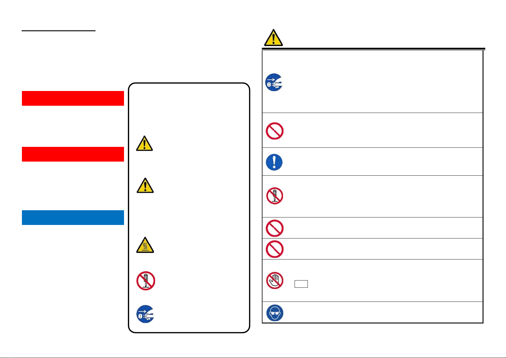
Safety Information............................................................................4
Bluetooth® Wireless Technology...............................................................7
General information .........................................................................8
Introduction.................................................................................................8
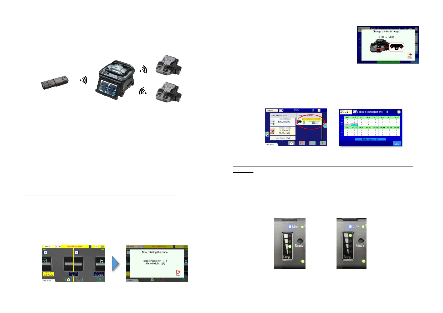
Wireless data communication ....................................................................9
Newly designed sheath clamp..................................................................11
Newly designed carrying case and work tray...........................................12
Other features ..........................................................................................14
Touchscreen Calibration ..........................................................................14
Description of product....................................................................16
Components of splicer..............................................................................16
Other necessary items for splicing operation...........................................17
Description of Splicer ...............................................................................18
Basic Operation .............................................................................21
Splicing work preparation.........................................................................21
Power supply............................................................................................22
Battery Operation .....................................................................................23
Turning Splicer ON/OFF...........................................................................26
Splicer settings check / READY screen ...................................................27
LCD Brightness Adjustment.....................................................................28
Wireless communication with tools ..........................................................28
Wind-protector automatic opening-and-closing function..........................28
Operation mode........................................................................................29
Select of the Splice mode.........................................................................31
Select of the Heater mode........................................................................32
Preparation of fiber...................................................................................34
Fiber coating stripping and cleaning of bare fiber....................................34
Fiber Cleaving when using a sheath clamp .............................................34
Fiber Cleaving when using a Fiber Holder...............................................35
Loading fiber in splicer .............................................................................37
Wind-protector motion and sheath clamp motion.....................................38
Arc Calibration..........................................................................................38
Splicing procedure....................................................................................39
Storing splicing results .............................................................................42
How to input Mode Title/Comment/Password..........................................42
Fiber proof test .........................................................................................42
Heating protection sleeve.........................................................................43
Maintenance of Splicing Quality.....................................................45
Cleaning and Checking Before Splicing...................................................45
Periodical checking and cleaning.............................................................46
How to remove and install the Protrusion of the sheath clamp ...............48
Wireless data communication ........................................................50
Wireless data communication function of the splicer...............................50
How to establish wireless data communication .......................................51
How to turn off the wireless data communication ....................................52
Blade Management Menu........................................................................54
Benefit of wireless data communication function.....................................54
Benefit of wireless security function “Smart Lock” ...................................56
Main Menu .....................................................................................58
Composition of Main Menu ......................................................................58
Splice mode menu..........................................................................59
Composition of Splice Menu ....................................................................59
Splice Mode .............................................................................................59
Heater Mode Menu.........................................................................70
Composition of the Heater Mode Menu...................................................70
Detail of the parameter in Heater Mode Menu.........................................73
Tube heating drop cable ..........................................................................74
Tube heating Splice-on-Connector ..........................................................74
Memory Menu ................................................................................75
Composition of the Memory Menu...........................................................75
Memory Menu Settings............................................................................75
Maintenance Menu.........................................................................77
Composition of the Maintenance Menu ...................................................77
Detail of the Maintenance Menu..............................................................77
Arc Calibration..........................................................................................77
Diagnostic Test ........................................................................................78
Dust Check...............................................................................................79
Motor Calibration......................................................................................79
Stabilize Electrodes..................................................................................79
Replace Electrodes..................................................................................80
Clear Arc Count........................................................................................80
Clear Cleaver Counter .............................................................................80
Battery Discharge.....................................................................................81
Motor Drive...............................................................................................81
Maintenance Info......................................................................................81
Splice Settings Menu......................................................................82
Composition of the Splice Settings Menu................................................82
How to change the settings......................................................................82
Other Settings Menu ......................................................................84
Composition of the Other Settings Menu.................................................84
Detail of the Other Settings Menu............................................................84
Machine Settings......................................................................................84
Supervisor Settings..................................................................................86

FUSION SPLICER 90S Rev5
3
Menu Lock Settings..................................................................................87
Bluetooth Menu ........................................................................................89
Cleaver Setting Menu...............................................................................90
Stripper Setting Menu...............................................................................92
Reference Guide............................................................................93
Instruction Manual and the Utility Software....................................94
How to install the instruction manual and the Utility Software .................94
Error Message List.........................................................................95
Questions and Troubleshooting...................................................100
Power Supply .........................................................................................100
Splicing Operation..................................................................................100
Tube-heating Operation .........................................................................101
Wireless data communication ................................................................101
Supervising.............................................................................................102
Other Functions......................................................................................102
Trademarks ............................................................................................102
W
arranty and Contact Address.....................................................103
Warranty.................................................................................................103
Contact Address.....................................................................................104

FUSION SPLICER 90S Rev5
4
Safety Information
The fusion splicer is designed for splicing Silica-based optical fibers for
telecommunications. Do not attempt to use this machine for other
applications Fujikura Ltd. gives much consideration and regard to personal
injury and any damages. Misuse of the machine may result in electric
shock, fire and/or serious personal injury and any damages.
Read and understand
all safety instructions.
Ask our service
centers for repair as
soon as possible.
Read this instruction
manual carefully
before operating this
machine.
Store this instruction
manual in a safe
place.
WARNINGS!
Disconnect the AC power cord from the AC adapter inlet or the wall
socket (outlet) immediately if user observes the following or if the
fusion splicer receives the following faults:
• Fumes, bad smell, noise, or over-heat occurs.
• Liquid or foreign matter falls into cabinet.
• Fusion splicer is damaged or dropped.
If this occurs, ask our service center for repair. Leaving the fusion
splicer in a damaged state may cause equipment failure, electric
shock or fire and may result in personal injury, death or fire.
AC adapter which be used for a fusion splicer is only an adapter for
exclusive use.
Using an improper AC power source may cause fuming, electric
shock or equipment damage and may result in personal injury, death
or fire.
Use the supplied AC power cord. Do not place heavy objects on the
AC power cord. Use of an improper cord or a damaged cord may
cause fuming, electric shock or equipment damage and may result in
personal injury, death or fire.
Do not disassemble or modify the fusion splicer, AC adapter or
battery. In particular, do not remove or bypass any electrical or
mechanical device (e.g. a fuse or safety switch) incorporated into the
design and manufacturing of this equipment. Modification could
cause damage that may result in personal injury, death, electric shock
or fire.
Never operate the fusion splicer in an environment where flammable
liquids or vapors exist. Risk of dangerous fire or explosion could
result from the fusion splicer’s electrical arc in such an environment.
Do not use compressed gas or canned air to clean the fusion splicer.
They may contain flammable materials that could ignite during the
electrical discharge.
Do not touch the electrodes when the fusion splicer is on and power
is supplied to the unit. The electrodes generate high voltage and high
temperatures that may cause a severe shock or burn.
Note Arc discharge stops when wind-protector is open. Turn the
fusion splicer off and disconnect the AC power cord before replacing
electrodes.
Safety glasses should always be worn during fiber preparation and
splicing operation. Fiber fragments can be extremely dangerous if it
comes into contact with the eye, skin, or is ingested.
The following alert symbols are used in
this instruction manual and machine to
indicate warnings and caution for safe
use. Understand the meanings of these
symbols.
WARNING!
There is a possibility of death or serious
injury resulting from improper use by
ignoring this indication.
CAUTION!
There is a possibility of personal injury or
physical loss resulting from improper use
by ignoring this indication.
Symbol means “Pay attention”
Pay attention to hot surface!
Symbol means “Must not do”
You must not disassemble!
Symbol means “Must do”
You must disconnect a plug!
Follow all safety instructions
Stop using it when it malfunctions
Instruction Manual

FUSION SPLICER 90S Rev5
5
WARNINGS!
Use only proper power source.
• Proper AC power source is AC100-240V, 50-60Hz. Check the AC power
source before use. Proper DC power source is DC10-12V. Improper AC
or DC power source may cause fuming, electric shock or equipment
damage and may result in personal injury, death or fire.
• AC generators commonly produce abnormally high AC output voltage or
irregular frequencies. Measure the output AC voltage with a circuit
tester before connecting the AC power cord. Such abnormally high
voltage or frequency from a generator may cause fuming, electric shock
or equipment damage and may result in personal injury, death or fire.
Make sure the generator is regularly checked and serviced.
•When using an AC generator with AC output voltage of AC220-240V
especially, Fujikura Ltd. recommends the following measures to correct
the condition.
1. Connect a step-down transformer between the generator and the AC
adapter in order to lower the AC voltage from AC220-240V to AC100-
120V.
2. Or, use an AC generator with AC output voltage of AC100V.
3. Or, use an AC generator that has an inverter circuit to stabilize the
output.
Do not modify, abuse, heat or excessively pull on the supplied AC cord.
The use of a damaged cord may cause fuming, electric shock or
equipment damage and may result in personal injury, death or fire.
The fusion splicer uses a three-prong (core) AC cord that contains an
earthed ground safety mechanism. The fusion splicer MUST be
Grounded. Use only the supplied three-prong (core) AC power cord.
NEVER use a two-prong (core) power cord, extension cable or plug.
Connect AC power cord properly to the fusion splicer (inlet) and wall
socket (outlet). When inserting the AC plug, make sure there is no dust or
dirt on the terminals. Engage by pressing the female plug into the fusion
splicer (inlet) and the male plug into the wall socket (outlet) until both
plugs are fully seated. Incomplete engagement may cause fuming,
electric shock or equipment damage and may result in personal injury,
death or fire.
Do not short-circuit the terminals of AC adapter and optional battery.
Excessive electrical current may cause personal injury due to fumes,
electric shock and equipment damage.
WARNINGS!
Do not touch the fusion splicer, AC power cord and AC plugs with wet
hands. This may result in electric shock.
Do not operate fusion splicer near hot objects, in hot temperature
environments, in dusty / humid atmospheres or when water-
condensation is present on the fusion splicer. This may result in
electric shock, fusion splicer malfunction or poor splicing performance.
When using optional battery, follow the instructions below.
Failure to follow these may result in explosion or personal injury.
• Do not charge battery with other methods than instructed.
• Do not discard battery into an incinerator or fire.
• Do not charge or discharge battery near a flame or under direct
sunlight.
• Do not excessively shake or jar the battery.
• If battery leaks of liquid residue, be careful handling the battery so
the liquid does not get in skin or eye contact. If it reaches contact,
immediately wash skin or eyes thoroughly and see the doctor.
Dispose of the battery and call the service center for replacement.
• Do not stack battery on top of AC adapter while charging.
• If charge did not complete in five hours or the "CHARGE" LED
does not turn ON, immediately stop charging and call the service
center for repair.
When transporting the carrying case using the shoulder belt, check the
belt and hooks for damage before use. Carrying the case with a
damaged shoulder belt may cause the belt to break or come off and
result in personal injury or equipment damage.

FUSION SPLICER 90S Rev5
6
CAUTIONS!
Do not store fusion splicer in any area where temperature and humidity
are extremely high. Possible equipment failure may result.
Do not touch protection sleeve or tube-heater during heating or
immediately after completion of heating. Their surfaces are very hot
and touching these may result in skin burn.
Do not place the fusion splicer in an unstable or unbalanced position.
The fusion splicer may shift or lose balance, causing the unit to fall.
Possible personal injury or equipment damage may result.
The fusion splicer is precision adjusted and aligned. Do not allow the
unit to receive a strong shock or impact. Possible equipment failure
may result. Use supplied carrying case for transportation and storage.
The carrying case protects the fusion splicer from damage, moisture,
vibration and shock during storage and transportation.
CAUTIONS!
Follow the below listed instructions for handling electrodes.
• Use only specified electrodes.
• Set the new electrodes in the correct position.
• Replace the electrodes as a pair.
Failure to follow the above instructions may cause abnormal arc
discharge. It can result in equipment damage or degradation in
splicing performance.
Do not use any chemical other than pure alcohol (99% or greater) to
clean the objective lens, V-groove, LCD monitor, etc., of the fusion
splicer. Otherwise, blurring, discoloration, damage or deterioration may
result.
The fusion splicer requires no lubrication. Oil or grease may degrade
the splicing performance and damage the fusion splicer.
The equipment must be repaired or adjusted by a qualified technician or
engineer. Incorrect repair may cause fire or electric shock. Should any
problems arise, please contact the nearest Fujikiura authorized
distributors.
RECYCLING and DISPOSAL
In European Union
In accordance with the European Parliament Directive 2002/96/EC,
electrical parts and materials that can be re-used and/or recycled have
been identified in order that the use of new resources and the amount of
waste going for landfill can be minimised.
In the European Union, do not discard this product as unsorted
municipal waste. Contact your local authorities.
In other countries
[Recycling]
To recycle this product, disassemble it first, sort each part separately by
material components and follow your local recycling regulations.
[Disposal]
This product can be disposed of same as the standard electric poroducts.
Follow your local disposal regulations.

FUSION SPLICER 90S Rev5
7
Bluetooth® Wireless Technology
・
The fusion splicer uses the Bluetooth technology for
wireless data communication.
・
The wireless data communication is done at a
frequency of 2.4GHz band, and employs the DSSS
modulation scheme. The estimated interference
distance is 10m or less.
CAUTION!
When using the fusion splicer, the optical fiber cleaver and the
ribbon fiber stripper near medical devices, turn the wireless
communication function of these off.
Turn the power of the fusion splicer off in the aircraft.
For the optical fiber cleaver and the ribbon fiber stripper, remove
batteries to turn off the wireless data communication.
Typical wireless certifications are:
USA FCC Rules Part 15 FCC ID
:
QOQ11
CANADA Industry Canada Rules RSS-247 IC
:
5123A-11
European Union RE directive 2014/53/EU
RE Directive: 2014/53/EU
EN300 328, EN301 489-1, EN301 489-17 and EN 60950-1
JAPAN Radio-wave Law Article38-24 paragraph 1 R209-J00255
・
If you have any questions for other countries, contact a nearest Fujikura
authorized distributor listed in the following web site:
https://www.fusionsplicer.fujikura.com/service/index.html
2.4 DS1

FUSION SPLICER 90S Rev5
8
General information
Introduction
This fusion splicer can splice a single optical fiber. Moreover, new functions
were implemented so the splicer has improved versatility. In order to master
the splicer, please read this instruction manual.
Splice mode
This fusion splicer has not only automatic modes (AUTO mode), but also
special modes. The AUTO mode consists of [SM AUTO], [MM AUTO], [NZ
AUTO], [DS AUTO] mode. Select the splice mode according to the fiber type.
If you do not know the fiber type, use the [AUTO SM/NZ/DS/BIF/MM] mode.
The splicer analyzes the core profile for fiber, identifies the fiber such as SMF,
NZDSF, MMF, BIF, etc. and selects the optimal splice mode automatically.
When using these AUTO modes, the automatic arc calibration function is
enabled.
The special modes consist of [SM-SM] for SMF (ITU-T G652), [NZ-NZ] for
NZDSF (ITU-T G655), [DS-DS] for DSF (ITU-T G653), MM-MM] for MMF
(ITU-T G651) and others.
Special modes requires executing [Arc Calibration] before splicing.
Automatic arc calibration function
This function calibrates the arc power in real time. When selecting an
automatic mode, this function is enabled. Performing the [Arc calibration]
function before splicing is not necessary.
It doesn’t work in the special splice modes. When using these modes,
performing [Arc calibration] before splicing is strongly recommended.
Automatic wind-protector
The wind-protector operation can be customized by choosing the preferred
operating mode for the wind-protector opening and closing
Fast heating system
When a protection sleeve is loaded, the heater lid will close automatically and
the shrink process will start automatically.
In addition, by using a dual sided
heater, we achieve faster heating times.
Field Assembly Optical connector splice
The assembly of a field splice-on optical connector can be performed by
heating of a protection sleeve can be performed by this fusion splicer.
Moreover, its versatility is improved by its portability.
Compatible with short length splices
In addition to standard cleave length splices, a splice with 5-mm cleaves is
also possible.
Upgrade of software
The firmware of the splicer can be upgraded to the latest version using the
“Data Connection” app.
Before getting “Data Connection”, refer to the section “Getting the Instruction
Manual and the Utility Software” and download the Utility Software first. Then
install the “Data Connection” program from the Utility Software.
A specialized tool is needed in order to perform the 5-mm cleave
length splices

FUSION SPLICER 90S Rev5
9
Wireless data communication
This splicer can wirelessly communicate with two fiber cleavers (CT50) and
a ribbon fiber stripper (RS02/03) via Bluetooth at the same time.
It can check and manage each cleaver individually.
This capability allows the splicer to monitor and change various settings within
the cleaver. The splicer can assess blade wear by analyzing the fiber image
after cleaving, and then inform the operator with an on-screen alarm. Once a
blade position has been expended, the splicer can then rotate the blade to the
next available unconsumed position.
The communication parameters between splicer, cleaver, and stripper are
setup prior to shipment when these items are ordered together. Once AAA
batteries are placed in the cleaver, and power supplied to the stripper, they
are immediately paired to the splicer. Upon pairing, the splicer is ready to
track cleaver blade life and to change the heating mode of the stripper,
depending on the splice mode, automatically.
Benefit of wireless data communication function with cleaver CT50
(1) It is difficult for operators to track blade wear. However, it is easy to detect
blade wear by correlating blade positions with cleaving errors given by the
splicer. If the splicer detects that a blade position has reached its cleave limit,
the splicer sends a command to the cleaver to rotate the blade to the next
position. By using this function, the operator can maximize blade life like never
before. The operator can now use a cleaver without worrying about tracking
blade life, and can be confident they are making reliable splices.
(2) The timing and judgment of blade rotation
made by the splicer can be adjusted in the
settings menu.
A message to raise blade height can also be
displayed when all 16 positions are expended.
There is no need for the operator to make
blade management decisions.
(3) The cleaver records cleaves per position per height of the blade. Even if an
operator changes the blade position by mistake, the splicer will display a
message on-screen to alert the user to this mistake. This further relieves the
operator of cleaver management issues.
Benefit of wireless data communication function with the ribbon fiber stripper
RS02/03
Ribbon fiber between 200 and 400 um coating diameter can be stripped with
this ribbon fiber stripper. The fusion splicer also wirelessly communicates with
RS02/RS03.
The ribbon fiber stripper settings are automatically changed according to the
splice mode.
To simplify field work, the operator can change the heat setting of the
RS02/RS03 at any time with the fusion splicer.

FUSION SPLICER 90S Rev5
10
Benefit of wireless security function “Smart Lock”
“Smart Lock” can be used by connecting a smartphone and the fusion splicer
via Bluetooth communication.
This function locks and unlocks the fusion splicer by Bluetooth communication
with a smartphone.
It will be locked automatically if the fusion splicer is stolen. Therefore, it is
possible to prevent unauthorized use after theft.
Furthermore, this function may help the effect of suppressing theft.
The
“
Splice+” smart phone application is required to use this feature.
Splice +
Pairing
Unlock
lock
Splice +

FUSION SPLICER 90S Rev5
11
Newly designed sheath clamp
Easy sleeve positioning
The sheath clamp is optimized for the 60mm length sleeve. When using a
60mm sleeve, it is easy to position the center of the protection sleeve over the
splice point.
e.g. in case setting protection sleeve on the right
(1) Hold both fibers, with your left hand positioned just behind the sheath clamp
(2) Slide the protection sleeve until it touches your left hand, while holding
tension on the splice.
(3) Slide left hand away from the protection sleeve
(4) Slide left hand away from the protection sleeve.
Fiber Retention Clamp
The sheath clamp features a secondary clamp, “Fiber Retention Clamp”, which
retains the fiber after the sheath clamp is opened. This mechanism prevents the
fiber from flying out after the sheath clamps open. When the fiber is lifted by hand,
the Fiber Retention Clamp opens and releases the fiber automatically. There is
a switch to control this retention system on top of the sheath clamp.
Sheath clamp (opened)
Fiber Retention Clamp
Photomicrograph
Fiber Retention Clamp
Yellow label:
release fiber
Green label:
retain fiber
*Recommended

FUSION SPLICER 90S Rev5
12
Compatibility with loose tube fiber
The sheath clamp has a retractable protrusion for splicing loose buffer fiber. The
switch for this feature is on the base of the sheath clamp. You can now easily
splice loose buffer fiber without changing the sheath clamp.
Newly designed carrying case and work tray
Carrying case
The new carrying case has more space inside, allowing you to store all the tools you
need. The work tray attached to the carrying case can be taken out.
The work tray can be fixed on a tripod stand to improve work efficiency.
Protrusion switch=OFF
Protrusion for loose tube
Protrusion switch=ON
Protrusion for loose tube
Open
Lid of carrying case
becomes a work
table
Remove work tray
from carrying case
Do not use the protrusion part when splicing standard fiber. Only
use this with loose buffer fiber, since the protrusion part may
damage the tight buffer fiber.
This protrusion part can be removed. Refer to “How to remove and
install the protrusion” section in this document.

FUSION SPLICER 90S Rev5
13
Work tray
The work tray has two drawers for storing the tools to prevent dust accumulation.
The drawers are just the right size for tools or battery pack.
Also, the work tray can be divided, so you can use it according to your work space.
Protection sleeve stand
The work tray has a stand to place the protection sleeve after heating.
Protection sleeve stand can be detached.
Drop cable holding stand
The work tray has a stand for placing the drop cable clamp (CLAMP-DC-12).
The stand has two positons. One is the position during splicing. Another is
the positon during heating.
Stripper SS03 + Cleaver CT50
Battery BTR-15, up to 2 units
Work tray
Push apart
For heating
For splicing
Detachable
Configuration1
Configuration 2
Push to divide
Protection sleeve stand

FUSION SPLICER 90S Rev5
14
Other features
Touch Panel Display & New designed Menu Screen
The fusion splicer has a touch panel display and newly designed menu. The
operator can select or change settings by touching icons on the monitor.
Sheet key & Classic Menu Screen
The fusion splicer also has an external sheet key and a classic menu. Press the
DOWN key in sheet key in [READY] screen. The classic menu appears. The
operator can now use the fusion splicer like previousfusion splicers.
Touchscreen Calibration
Touch detection accuracy of the touchscreen were adjusted in the factory before
shipping. However, the accuracy could change due to various reasons.
If the response of the touchscreen is not good, adjust it according to the following
procedure.
Adjustment procedure
Press DOWN key in [READY] screen and enter the classic menu.
1. Select [Touchscreen Calibration] function in the [Maintenance Menu] of the
classic menu.
2. Follow the procedures and finish the calibration.
Press DOWN key.
Classic Menu

FUSION SPLICER 90S Rev5
15
Power supply connector for the device
The USB type A connector of this fusion splicer can supply power to devices like
an LED lamp, for splicing in a dark environment, or to charge a cell phone *
*NOTE: It is not guaranteed to charge all smartphones.
Connector type
Current capacity
USB 2.0 Type A
Max 0.5A
When the fusion splicer battery is used to power other devices, the
number of splice and heat cycles will be reduced.
When the remaining battery power is low, the power supplied to
external devices will become unstable.
Connecting a device outside the above specifications may affect
splicing behavior. When the behavior of the fusion splicer is
unstable, remove the device.

FUSION SPLICER 90S Rev5
16
Description of product
Components of splicer
The standard package of the splicer is the following.
Check the equipment items mentioned in this list.
Standard package list (1 of 2)
Standard package list (2 of 2)
Alcohol Dispenser
[AP-02]
Quick Reference Guide
[QRG-02-E]
Optical Fiber
Cleaver
[CT50]
Wireless/PC/Clamp Setting
Guide
[SG-03-E]
Warning and Cautions
[WAC-01-E]
Single Fiber
Stripper
[SS03]
Core Alignment
Fusion Splicer
[90S]
Carrying Case
[CC-39]
AC Adapter
[ADC-20]
AC Power Cord
[ACC-xx]
USB Cable
[USB-01]
Electrodes (spare)
[ELCT2-16B]
Fiber Holder
Set Plate
[SP-03]
Work Table Left
[WT-08L]
Work Table Right
[WT-08R]
Work Table J-Plate
[JP-09]
Battery Pack
[BTR-15]
Fusion splicer
Strap
[ST-02]
Tripod Screw
[TS-03]
Carrying Case
Strap
[ST-03]

FUSION SPLICER 90S Rev5
17
Other necessary items for splicing operation
Fiber
coating
diameter
UV coating
250µm
Nylon coating
900µm
Fiber
holder
(Optional)
[FH-70-250]
* Old model [FH-60-250] can
also be used.
[FH-70-900]
* Old model [FH-60-900] can
also be used.
Fiber
protection
sleeves
(optional)
Standard sleeve
60mm length [FP-03], [FP-03M]
40mm length [FP-03 (L = 40)]

FUSION SPLICER 90S Rev5
18
Description of Splicer
Structure
90
LCD monitor
Tube heater
Wind-Protector
USB port Mini
USB port A
Ribbon Stripper terminal
Wind protector
Power unit dock
External terminal
Top view
Front view
Side view

FUSION SPLICER 90S Rev5
19
V-groove illumination
LED
LED
Inside of Wind protector
Electrode
Electrode
V-groove
V-groove
V-groove Clamp
V-groove Clamp
Sheath Clamp
Fiber Retention Clamp
Switch
Fiber Retention Clamp
Switch
Fusion work area
Other manuals for 90S
1
Table of contents
Other Fujikura Welding System manuals

Fujikura
Fujikura 70S User manual

Fujikura
Fujikura 62S User manual

Fujikura
Fujikura 90S User manual

Fujikura
Fujikura CB-08 User manual

Fujikura
Fujikura FSM-50S User manual

Fujikura
Fujikura FSM-40S User manual

Fujikura
Fujikura KSP75-FP-005468 User manual

Fujikura
Fujikura QRG-02 User manual

Fujikura
Fujikura FSM-60S User manual

Fujikura
Fujikura 19S+ User manual
Popular Welding System manuals by other brands

Weco
Weco WF-104 instruction manual

Oerlikon
Oerlikon CITOTIG 250 AC/DC Safety Instructions for Operation and Maintenance

Lincoln
Lincoln INVERTEC PC 65 Operator's manual

STAMOS
STAMOS S-MIG 200 user manual

EWM
EWM Taurus 355 Synergic S LP MM TKM operating instructions

INNO Instrument
INNO Instrument M9 user manual