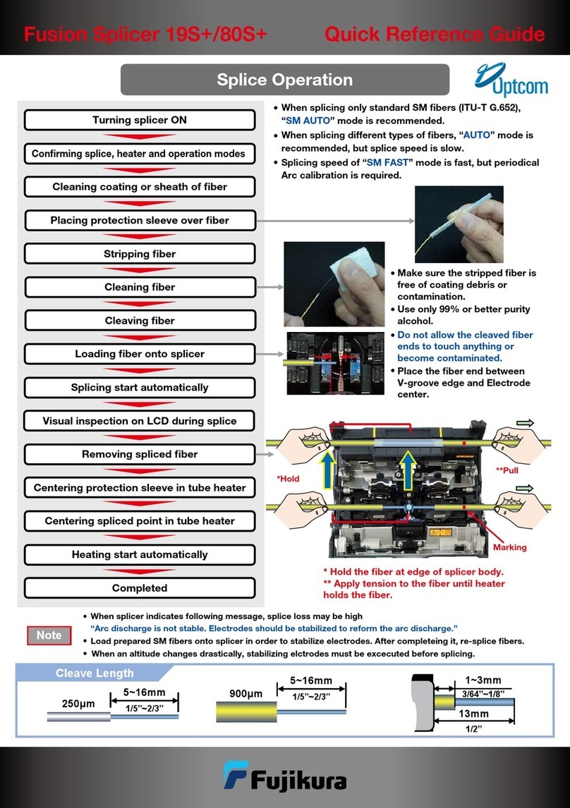
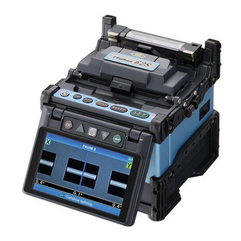
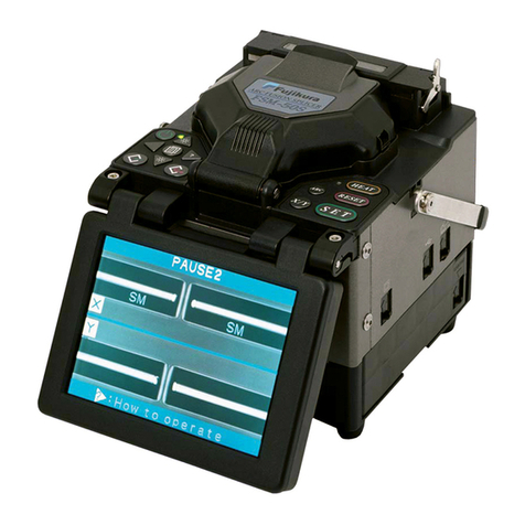
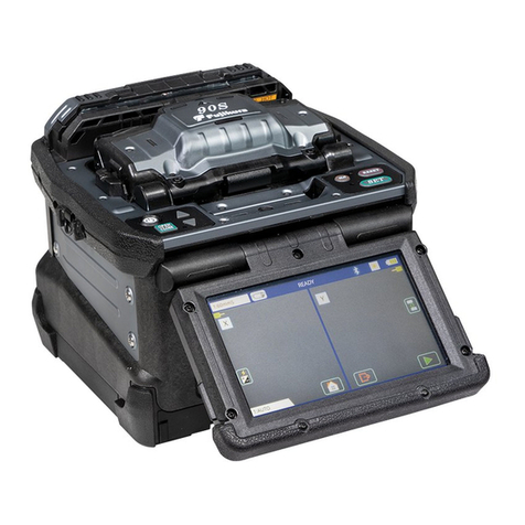
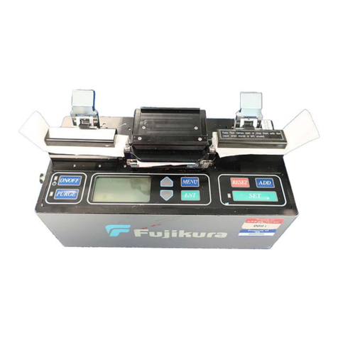
Fujikura FSM-40S User manual

KSP75-0086-51-02 (3)
Fujikura Proprietary Document
No part of this document may be transferred to any third party
without prior written consent from Fujikura Ltd.
ARC FUSION SPLICER
LEVEL 2
MAINTENANCE MANUAL
FSM–40S

Page 2
Table of Contents
§ 1. Introduction....................................................................................................4
§ 2. Notes to users..................................................................................................5
§ 2.1. Warning and Cautions for Maintenance......................................................5
§ 2.2. Abbreviations ...............................................................................................9
§ 2.3. General Overview ........................................................................................9
§ 2.3.1. Composition of FSM-40S.....................................................................................................9
§ 2.3.2. Basics and Preparations.......................................................................................................10
§ 2.3.3. Cleaning and checking before adjustment ..........................................................................11
§ 2.4. Accessing Secret Menu’s and Secret Key Functions ..................................12
§ 2.4.1. “Secret”Menu.....................................................................................................................12
§ 2.4.2. Password..............................................................................................................................14
§ 2.4.3. Total Initialization of all data (Emergency only) ................................................................14
§ 3. Mechanical Assembly................................................................................15
§ 3.1. Focus/Camera Assembly............................................................................15
§ 3.1.1. Camera Assembly................................................................................................................15
§ 3.2. Electrode Unit Assembly............................................................................17
§ 3.3. Z-Axis Unit Assembly.................................................................................19
§ 3.3.1. Z-Axis Unit Assembly.........................................................................................................19
§ 3.3.1.1 Sheath Clamp Top........................................................................................................19
§ 3.3.1.2 Fiber Clamp Arm.........................................................................................................20
§ 3.3.2. Setting Clamp Top...............................................................................................................21
§ 4. Mechanical Adjustment............................................................................22
§ 4.1. Installing Focus Unit ..................................................................................22
§ 4.2. Installing Z-Unit.........................................................................................25
§ 4.3. Installing Tube Heater................................................................................26
§ 4.4. Installing Wind Protector...........................................................................27
§ 4.5. Installing Power Unit Dock to Base-Frame................................................28
§ 4.6. Adjusting the Set-Plate Position to the V-groove .......................................29
§ 4.7. Adjusting Z-Clamp Unit Height.................................................................29
§ 4.8. Adjustment Fiber Clamp Position.............................................................30
§ 4.9. Adjusting Display Image............................................................................31
§ 4.9.1. Rough Adjusting Display Image.........................................................................................31
§ 4.9.2. Adjusting Camera Inclination.............................................................................................32
§ 4.9.3. Image Alignment.................................................................................................................34
§ 4.9.4. Wind Protector Mirror Adjustment .....................................................................................36
§ 4.10. Adjustment of XY Unit.............................................................................37
§ 4.10.1. Confirmation of XY adjustment condition........................................................................37
§ 4.10.2. Confirmation of Swing-arm Travel...................................................................................39
§ 4.11. Adjustment of Focus Motor LS-dog’s Position.........................................40
§ 4.12. Adjustment of Focus-Mechanical-Stopper’s Position..............................41
§ 4.13. Confirmation of Z Motor End Play..........................................................42

Page 3
§ 4.14. Install the Discharge Circuit ....................................................................43
§ 4.15. Installing Monitor....................................................................................44
§ 4.16. Installing Connector Box..........................................................................45
§ 4.17. Installing Panel.........................................................................................46
§ 4.18. Tube Heater Adjustment..........................................................................47
§ 4.18.1. Adjust Tube Heater Temperature ......................................................................................47
§ 4.19. Splice Test.................................................................................................51
§ 4.19.1. Estimate Check..................................................................................................................51
§ 4.19.2. Stuff Check........................................................................................................................52
§ 4.19.3. Arc Calibration..................................................................................................................52
§ 5. Electrical......................................................................................................53
§ 5.1. PCB Connection.........................................................................................53
§ 6. How to:.........................................................................................................54
§ 6.1. Replace PCB ..............................................................................................54
§ 6.1.1. Preparations before Replacement........................................................................................54
§ 6.1.2. Removal of PCB..................................................................................................................54
§ 6.1.3. Installation of PCB..............................................................................................................55
§ 6.1.4. Adjusting Voltage Indicator for 40S....................................................................................56
§ 6.2. Software Upgrade ......................................................................................57
§ 6.2.1. Software Upgrade with Programming Chip Device ...........................................................57
§ 6.2.2. Software Upgrade with RS-232C cable ..............................................................................58
§ 6.2.2.1 Install of PCUG software.............................................................................................58
§ 6.2.2.2 Upgrading of software. ................................................................................................58
§ 6.2.3. Data Download Software with RS-232C............................................................................59
§ 7. Trouble Shooting ........................................................................................61
§ 7.1. ERROR 01 Too Long Fiber........................................................................61
§ 7.2. ERROR 01 Too Long Fiber........................................................................61
§ 7.3. ERROR 03 Fiber too Dusty........................................................................61
§ 7.4. ERROR 04 Motor Overrun........................................................................62
§ 7.5. ERROR 05 Close Cover.............................................................................62
§ 7.6. ERROR 06 Cover Opened Error...............................................................62
§ 7.7. ERROR 07 Motor Trouble.........................................................................63
§ 7.8. ERROR 08 Fiber Judge Error...................................................................63
§ 7.9. ERROR 09 (ARC) Calibration Error........................................................63
§ 7.10. ERROR 10 Fiber Separate Error.............................................................64
§ 7.11. ERROR 11 Fiber Set Error......................................................................64
§ 7.12. Splicer does not boot up ...........................................................................64
§ 7.13. Heater Trouble .........................................................................................65
§ 8. Appendices...................................................................................................66
§ 8.1. The Check-Sheet for the Adjusting Display Image....................................66
§ 8.2. List of the necessary tools for FSM-40S adjustment..................................67

Page 4
§ 1. Introduction
This manual describes the mechanical assembly, adjustment, and maintenance of Fujikura’s FSM-40S
fusion splicer. When maintaining the FSM-40S, it is important to locate the exact problem and make
the necessary repairs properly. This manual will provide processes to repair the FSM-40S in a safe,
concise, and easy to follow manner for a qualified technician.

Page 5
§ 2. Notes to users
§ 2.1.Warning and Cautions for Maintenance
This maintenance manual also includes safety requirements.
•Read this manual carefully before performing any maintenance procedure to the splicer.
•Keep this manual in a safe place.
Fujikura Ltd. accepts no responsibility for personal injury or physical loss including equipment damage
resulting from improper use or modification.
This maintenance manual indicates warnings and cautions by using alert symbols. It is important to understand
what it means.
WARNING
There is a possibility of personal death or serious injury resulting from improper use
by ignoring this indication.
CAUTION
There is a possibility of personal injury or physical loss resulting from improper use by
ignoring this indication.
Symbol means “Pay Attention.”
The left symbol indicates “Pay attention to explosion.”
Symbol means “Must not do.”
The left symbol indicates “You must not disassemble.”
Symbol means “Must do.”
The left symbol indicates “You must disconnect the AC power cord from the wall socket
or the appliance inlet.”
Alert Symbol
Example of Alert Symbol

Page 6
WARNING
The appliance inlet is used to disconnect the power cord when you disassemble the splicer.
Check to insert the all connector correctly before packaging.
Never maintain the splicer in an environment where flammable liquid or vapor exists. Extremely
dangerous fire and explosion could result from the splicer’s electrical arc in such an environment.
Do not disassemble or modify AC adapter and battery pack. In particular, do not remove or bypass
any electrical or mechanical device (e.g. a fuse or safety switch) incorporated into the design and
manufacturing of this equipment.
Check the connector to insert correctly before discharging.
During arc discharge, the electrodes generate high voltage and high temperature, and it causes
personal injury. Do not touch the electrodes during the maintain (though arc discharge stops when
the wind protector is opened). Turn the splicer power off, and disconnect the AC power cord (or
remove the battery pack) when replacing the electrodes.
This equipment is designed for splicing optical glass fiber for telecommunication. Do not attempt to
splice any materials other than the optical glass fibers.
Never use a canned type air cleaner to remove dust, or to clean the splicer. The electrical arc may
ignite any remaining gas mixture.
Safety glass should always be worn during the fiber preparation and the splicing process. A glass
fiber fragment can be extremely dangerous if it comes into contact with the eye, skin, or is ingested.
Use only specified power supply unit and proper AC power source.
•Only the AC adapter / battery charger (ADC-07) or the battery pack (BTR-04) can be used for
supplying power to the splicer.
•Proper AC power source to the ADC-07 is AC100-240V, 50-60Hz. Check the AC power source
before use. Improper AC power source out of the range can cause personal injury, emitting smoke
or equipment damage.
•Abnormal high AC output voltage or frequency from an AC generator is a common fault.
Measure the output AC voltage by a circuit tester before connecting the AC power cord.
Improper high voltage or frequency from generator causes personal injury, emitting smoke or
equipment damage.
Use only specified AC power cord. Do not put a heavy object on the power cord. Also, do not pull,
heat up or modify the power cord. Using an improper cord or a damaged cord can result in a fire,
emitting smoke, equipment damage or personal injury.

Page 7
WARNING
Connect the AC power cord properly to the appliance inlet and wall socket. When inserting the AC
plug, confirm no dust or dirt on terminals, and insert it to the end. Incomplete connection can cause a
fire, emitting smoke or personal injury.
Connect the AC adapter / battery charger to electrical ground when using it. It is possible to connect
through a third pin of AC plug. No connection to electrical ground can cause personal injury.
Use only the specified battery charger (ADC-07) to recharge the battery pack (BTR-04) with a
battery charger cord (DCC-08). Personal injury or equipment damage can result from using not
specified battery charger. Proper AC power source to the ADC-07 is AC100-240V, 50-60Hz. Check
the AC power source before use. Improper AC power source can cause personal injury, emitting
smoke or equipment damage.
The appliance inlet is used to disconnect the power cord when the splicer is abnormal. Be sure to
position the splicer so that it is easy to disconnect the power cord.
Disconnect the AC power cord from the appliance inlet or the wall socket when the equipment emits
smoke or bad smell, or is noisy or heated up. Leaving the abnormal condition can cause a fire,
personal injury or equipment damage.
Disconnect the AC power cord from the appliance inlet or the wall socket when the equipment is
damaged (e.g. by dropping). It may cause personal injury or equipment damage.
Disconnect the AC power cord from the appliance inlet or the wall socket when liquid (e.g. water) or
an object (e.g. screw) enters to inside the splicer. It can cause personal injury or equipment damage.
Do not touch the splicer, AC power cord and AC plug with a wet hand. It can cause personal injury.
Do not operate and maintain the splicer when it is wet with dew. It can cause personal injury or
equipment damage.
Do not use the splicer in circumstance of extremely hot temperature. It may cause personal injury or
equipment damage.
Do not throw the battery pack away into a fire. Or, do not heat it up. It can cause a dangerous
explosion.
Do not short-circuit both terminals of the battery pack and the AC adapter / battery charger. Large
electrical current can cause personal injury, a fire or equipment damage.

Page 8
CAUTION
Do not store the equipment in any area where extreme heat and humidity are present. It may cause
equipment damage.
During / after heating the splice protector, do not touch the ceramic heater and the splice protector.
The high temperature may cause personal injury.
Do not place the splicer at an unstable place. In a case of dropping the equipment, it can cause
personal injury or equipment damage.
Precise adjustment and alignment have been made to this splicer. Do not give a strong shock. Use a
carrying case to transport and store the splicer. The carrying case will prevent damage and provide
protection from moisture, vibration and shock during storage and transportation.
Keep the splicer free from sand or dust. It degrades the splicing performance.
Replace the electrodes properly.
•Only specified electrodes can be used.
•Set the new electrodes to the correct position.
•Replace the electrodes as a pair.
Not following the above cautions can cause abnormal discharge. And, it can result in equipment
damage or degrading the splicing quality.
Do not use any other chemical except alcohol to clean the objective lens, V-groove, mirror, LCD
monitor, body and so on. Doing so may cause blurring, discoloration or deterioration.
The splicer requires no lubrication. Oil may degrade the performance and damage the splicer.
Repair or re-adjustment should be performed by an authorized engineer, except the electrodes
replacement. Failure to repair the equipment can result in personal injury or equipment damage.
Please contact a sales agency in your country.

Page 9
§ 2.2.Abbreviations
Cap screw:Hexagon Socket Head Cap Screw
Set screw:Hexagon Socket Set Screw
WS2:Small Circular Washer of 2 mm in nominal diameter
WF2:Finished Circular Washer of 2 mm in nominal diameter
Phillips-headscrew:Cross Recessed Phillips-headScrew
Countersunk screw:Cross Recessed Countersink head Screw
Pan-headscrew: Cross Recessed Pan-headScrew
T=20:Tightening Torque is 20kgf·cm. (1kgf·cm = 9.80N·cm)
SLG:Screw Locking Glue
§ 2.3.General Overview
§ 2.3.1. Composition of FSM-40S
FSM-40S composes of the following unit.
(1) XY unit (2) Heater unit
(3) Focus unit (4) Base unit
(5) Electrode unit (6) Battery unit
(7) Z axis unit (8) Monitor unit
(9) Wind Protector unit

Page 10
§ 2.3.2. Basics and Preparations
Name of keys –Refer to Fig. 2.3.1.
MENU
EXIT
ENT
ON
HELP
ARC
X/Y
RESET
HEAT
SET
OFF
/
†MENU‡ key † ‡† ‡† ‡† ‡ key †HELP‡ key †ARC‡ key
†ON/OFF‡ key
†
X/Y
‡
key
†EXIT‡ key †ENT‡ key †RESET‡ key †SET‡ key †HEAT‡ key
Fig.2.3.1
<ON/OFF>key •••Turns power on and off. To turn off power, press and hold key untill the LED
color changes from green to red.
<HELP>key •••Displays [HELP] screen.
<ARC> key •••Executes re-arc discharge at end of splicing.
<X/Y> key •••Selects frame image display, X-direction enlarged, Y-direction enlarged or X-Y
direction composite image.
<RESET> key •••Return system to [READY] state from any state.
<HEAT> key •••States tube heater heat cycle
<SET> key •••Start splicing operation. This key is also used to cancel monitor power saving
state.
<MENU> key •••Open [Main Menu] screen. According to circumstances, changes manual drive
motor.
<EXIT> key •••Return system to previous menu screen.
<ENT> key •••Execute or select command or parameter on menu screen.
< >< > key •••Used to move cursor or change parameters. According to circumstances, drives
XY-motor or Focus-motor manually.
< >< > key •••Used to change pages. According to circumstances, drives Z-motor manually.

Page 11
§ 2.3.3. Cleaning and checking before adjustment
Before adjustment, do the following work. Refer to “INSTRUCTION MANUAL for FSM-40S”for
further information.
•Clean V-grooves
•Clean Fiber Clamp Chips
•Clean Wind Protector Mirrors

Page 12
Secret Menu 1/5
+
ENT:Select
Corner
Check
EXIT:Exit
st
Camera
Position
Focus
&
Electrode
Stuff
Check
Config
Code
Disp
Config
Code
Input
:Change
Page
Estimate
Test
Secret Menu 2/5
+ENT:Select
Heater
Adjustment
EXIT:Exit
st
Voltage
Adjustment
:Change
Page
HeatAD-250 80bit
HeatAD-100 230bit
AD-12V 152bit
Secret Menu 3/5
+ENT:Select
Splice
Database
Init
EXIT:Exit
st
Splice
Mode
Init.
Heater
Mode
Init.
Utility
Init.
:Change
Page
§ 2.4.Accessing Secret Menu’s and Secret Key Functions
§ 2.4.1. “Secret”Menu
At “READY”, press UP, DOWN and MENU at the same time. Secret Menu consists of 4 pages.
Using Secret Menu, software version needs to be later than V01.09.
Page 1 of 5 Corner Check – Background brightness indicator.
Camera Position- Use when aligning camera mechanical position.
Focus & Electrode – Use when adjusting focus and position of
electrodes.
Estimate Test– Estimation confirmation test.
Stuff Check – Checks stuff amount. Specification = 30±5.
Config Code Disp. - “Config Code”includes many calibration
parameters for the splicer. These “codes”have a relation to the
following: Serial Number, ICORE, Heater Calibration, Fiber Parameter, Voltage Adjust Parameter and
others.
Config Code Input - This command should be used after replacing the CPU Board
Page 2 of 5 Heater Adjustment – Use when calibrating heater unit
Heat AD-250/100 – Result of Heater Adjustment
Voltage Adjustment – Use when calibrating voltage value
AD-12V – Result of Voltage Adjustment
Page 3 of 5 Splice Database Init. - Initializes splice database area and the
database area to the condition whenshipped . When database area
is upgraded, perform this command.
Splice Mode Init. - Initializes all arc parametersof all 100 splice
modesin both the user programmable area and the database area to
the condition whenshipped from the factory. The splicer software
on the ROM chip contains these initial parameters
Heater Mode Init. - Initializes all heater parametersof all 40
heater modesin both the user programmable area and the database
area to the condition when shipped from the factory. The splicer software on the ROM chip contains
these initialparameters.
Utility Init. - Initializes all parameter of “Utility”including Configurations.

Page 13
Secret Menu 5/5
+ENT:Select
Focus
Home
Adjustment
EXIT:Exit
st
FCS
Home
X 1500ms
:Change
Page
FCS
Home
Y 1600ms
Page 4of 5
Arc Count Input - Edits Arc Count
Total Arc Count Input - Edits Total Arc Count
True AP1, AP2, AP3, and Gap Center- Result of “ARC
CALIBRATION”
Page 5of 5
Focus Home Adjustment –Use when calibrating “Focus Home
Position”
FCS Home X, Y – Result of “Focus Home Adjustment”.
Input Port Status.– Shows status of all Input Port and A/D
Converters. Note - Only RESET switch is available to exit this
menu.
7 6 5 4 3 2 1 0
S0 MENU UP DOWN LEFT RIGHT ENT EXIT
S1 HELP SET ARC X/Y L-FoXR L-FoXF L-XR L-XF
S2 L-ZRR L-ZRF L-ZLR L-ZLF L-FoYF L-FoYR L-YR L-YF
IN2 COVER L-TEMP H-Temp3 H-Temp2 H-Temp1 HEAT RESET
IN4 Magnet2 Magnet1
AD Voltage Pressure Temp Humid Heater3 Heater2 Heater1
(MENU UP DOWN..etc ) is Key Pad.
Slanting Font (L-????) is Limit Switch. For example, L-ZRF is limit of ZR motor, Forward direction.
COVER is window protector cover magnet sensor.
L-TEMP: if heater temp is lower than finish temp setting, ON.
H-Temp 1: if heater temp is higher than heating temp setting, ON.
H-Temp2 and 3are not used.
Magnet 1 and 2are magnet sensors, which are used to judge power source type.
Heater 2 and 3are not used.
Secret Menu 4/5
+ENT:Select
Arc
Count
Input
EXIT:Exit
st
Total
Arc
Count
Input
True
AP1
Gap
Center
:Change
Page
True
AP2
True
AP3

Page 14
§ 2.4.2. Password
Factory password to enter “Configurations”is “ARUKIJUF”. Note - After entering “Secret Mode”,
password is no longer required.
§ 2.4.3. Total Initialization of all data (Emergency only)
With splicer off, press “MENU”, “EXIT”, and “X/Y”at the same time and hold, then press the
“ON/OFF”to turn the splicer on.
Note - All Parameters of All Splice Modes, All Heater Modes, Utility, and Secret are initialized to
program set values.

Page 15
§ 3. Mechanical Assembly
§ 3.1.Focus/Camera Assembly
§ 3.1.1. Camera Assembly
1. Refer to Fig. 3.1.1 for steps 2 ~ 4.
2. Attached Kyoutou-Mirror onto Kyoutou with cap screw (M2×6, T=2, SLG).
3. Insert 0.3mm thick Lens-Liner between Lens and Kyoutou. Screw Lens in Kyoutou.
4. Insert CCD-Adapter with CCD-Camera into Kyoutou, and attachwith set screw (M3×3, T=2).
Note-Pay attention the directionof installationCCD-Adapter for X and Y positions (Refer to Fig.
3.1.2).
CCD Camera Unit
(S1330R-12)
Lens Shim (t=0.3)
(S1330M-03-03)
Don’t remove!
Objective Lens
Don’t remove!
Kyoutou
(S1330M-03-01)
Kyoutou Mirror
(S1330R-16)
Cap screw M2×6
(T=2, SLG)
Set screw M3×3
(T=2)
Not reverse
Fig. 3.1.1
Kyoutou Y Unit
Attention
Connector position
Kyoutou X Unit
Fig. 3.1.2

Page 16
5. Refer to Fig. 3.1.3 for steps 5 ~ 6.
6. Attach Focus Adjuster on Kyoutou Unit with cap screw (M3×10, T= temporary, WS3)
7. Attach Focus Arm Joint Plate on Kyoutou with cap screw (M3×10, T= temporary, WS3)
Focus Adjuster
(S1330M-03-12)
Focus Arm Joint Plate
(S1330M-03-07)
Cap screw M3×10
(WS3)
Cap screw M3×10
(WS3)
Fig. 3.1.3

Page 17
§ 3.2.Electrode Unit Assembly
Description
Refer to Fig. 3.2.1. The electrode unit consists of the electrode unit, electrode, and LED. Phillips-head
screw (M2×8, T=2) is used with the anode electrode holder and the cathode electrode holder to secure
the electrodes. The chamfered electrode holder (holds V-groove LED) is located on the cathode side.
Nut M2
LED Holder
(S1330M-01-10)
LED Holder
Cathode Electrode Holder
(S1330R-05)
V-Groove LED Screw Stopper
(S1330M-01-10)
Phillips-head screw
M2×8 (T=2)
Electrode
Electrode Base
(S1330M-01-01)
Nut M2
Anode Electrode Holder
(S1330R-04)
Anode Electrode
leaf Spring
Cathode Electrode
leaf Spring
Electrode
LED (KR5004X)
Phillips head screw
M2×4 (T=2, SLG)
Pan-head screw
M2×8 (T=2)
Phillips head screw
M2×4 (T=2, SLG)
Phillips-head screw
M2×8 (T=2)
Pan head screw
M2×8 (T=2)
LED (KR5004X)
Fig. 3.2.1

Page 18
1. Refer to Fig. 3.2.2.
2. Place LED into LED-Holder.
3. Place LED-Holder onto electrode unit. Apply by pushing LED-Holder from diagonally bottom to
diagonally top.
4. Attach with Pan-head screw (M2×8, T=2) and nut (M2).
Hanging
Pushing
Fig. 3.2.2
5. Install electrodes by applying light pressure to the back of electrode base (Refer to Fig. 3.2.3).
6. Attach with Phillips-head screw (M2×8, T=2)
Pushing
Fig. 3.2.3

Page 19
§ 3.3.Z-Axis Unit Assembly
§ 3.3.1. Z-Axis Unit Assembly
Z-Axis-Unit consists of two elements, Z-Clamp-Unit and Z-Motor-Unit.
§ 3.3.1.1 Sheath Clamp Top
1. Refer to Fig. 3.3.1.
2. Insert Super-Shaft (h7-1518)through Sheath-Clamp•and Hinge‚.
3. Insert Fiber-Pusher-Spring†betweenFiber-Pusherƒand Sheath Clamp•.
4. Press Fiber-Pusher ƒinto SheathClamp •, install Magnet-Catcher (Front)„and Magnet-Catcher
(Rear)…with each two phillips-head screws (M2×4, T=3). Note –Front and rear Magnet Catcher
are not interchangeable. Insure that Fiber-Pusherƒmoves smoothly after installation.
Phillips-head screw M2×4
(T=3)
Magnet-Catcher(Front)„
(S1330M-04-05)
Magnet-Catcher(Rear)…
(S1330M-04-05)
Fiber-Pusherƒ
(S1330R-24)
Hinge‚
Sheath Clamp Spring†
(S1330M-04-07)
Sheath Clamp•
(S1330R-22)
Super-Shaft h7-1518
Fig. 3.3.1

Page 20
§ 3.3.1.2 Fiber Clamp Arm
Note - Fiber-Clamp-Arm, Right side illustrated.
1. Refer to Fig. 3.3.2.
2. Insert Clamp-Arm-Shaftƒthrough Clamp-Arm (right)•and Clamp-Arm-Bracket‚.
3. Attach Clamp-Arm-Shaftƒto Clamp-Arm (right) with set screw (M2×2 with flat type T=1.5). Note
- position axes pin chamfer to align with set screw (M2×2).
4. Make Clamp-Arm (right)•parallel with base of Clamp-Arm-Bracket‚by adjusting set screw
(M2×3 with flat type, SLG) (Refer to Fig. 3.3.3).
Clamp-Arm (right) •
(S1330R-26)
Set screw M2×2 with flat type
(T=1.5, SLG)
Clamp-Arm-shaftƒ
Clamp-Arm-Bracket ‚
(S1330M-04-11)
Set screw M2×3 with flat point
(for adjustment of Clamp-Arm parallel, SLG)
Clamp-Arm(left)
uses this-side hole.
Fig. 3.3.2
Set parallel with set screw M2×3
Fig. 3.3.3
Table of contents
Other Fujikura Welding System manuals

Fujikura
Fujikura 90S User manual

Fujikura
Fujikura 70S User manual

Fujikura
Fujikura 19S+ User manual

Fujikura
Fujikura FSM-60S User manual

Fujikura
Fujikura 62S User manual

Fujikura
Fujikura 90S User manual

Fujikura
Fujikura KSP75-FP-005468 User manual

Fujikura
Fujikura FSM-50S User manual

Fujikura
Fujikura FSR-02 Assembly instructions

Fujikura
Fujikura QRG-02 User manual
Popular Welding System manuals by other brands

Cebora
Cebora SOUND MIG 3840/T Pulse Service manual

Telwin
Telwin PCP 28 LCD instruction manual

Helvi
Helvi GLOBUS 201 instruction manual

Sealey
Sealey SUPERMIG150.V4 quick start guide

Miller Electric
Miller Electric MO-395 owner's manual

Lincoln Electric
Lincoln Electric INVERTEC V320-T AC/DC Operator's manual