The allowsadjustmentsof±5.0°Cintheroomsensor(S1)
inrelationtothestandardcalibration.Forthisjustpressthekeyfor15secondsuntil
appearingtheindication .Usethe same procedure to modify the value of
thisfunction.
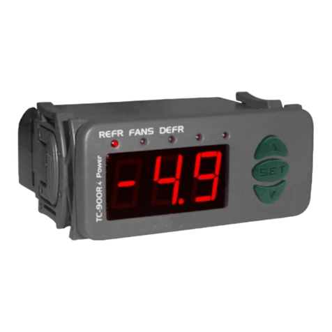
TC-900RG2 slim
Theluminouspointerinthefrontalsignalsthestatusofthecontroller:
Thecontrollerisinrefrigerationmode,withthecompressor
andfan ON. Whenthe instrument isin refrigeration withthe stopped indicationled
blinksinalesserfrequency.
Thecontrollerisinrefrigerationmode,withthecompressor
andthefanOFF. mode
a
Ledblinking
Ledturnedoff
Ledturnedon Thecontrollerisindefrost ,withthecompressorand
fanOFFandtheresist ncesON.
RoomsensorinshortcircuitortemperatureaboveofP8
s openedor
E sensordamagedortemperatureinthesensorbelowof
-30 ºC or above of ºC. In this situation the duration of the thawing will be of 10
minutes.
Room ensor temperaturebelowofP7
vaporator50
INDICATION DISPLACEMENT (OFFSET)
SIGNALLING
DIGITAL CONTROLLER FOR
REFRIGERATION AND DEFROST
Version 01
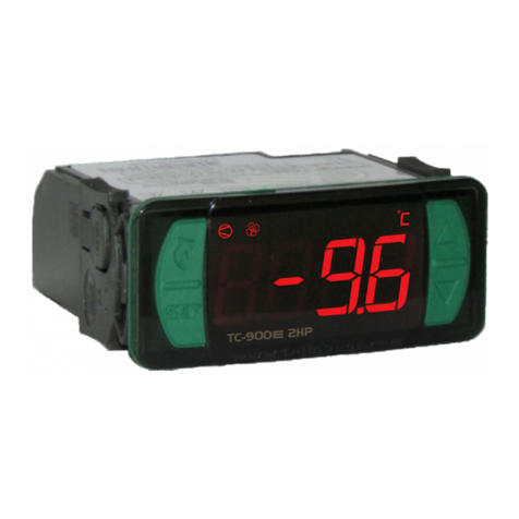
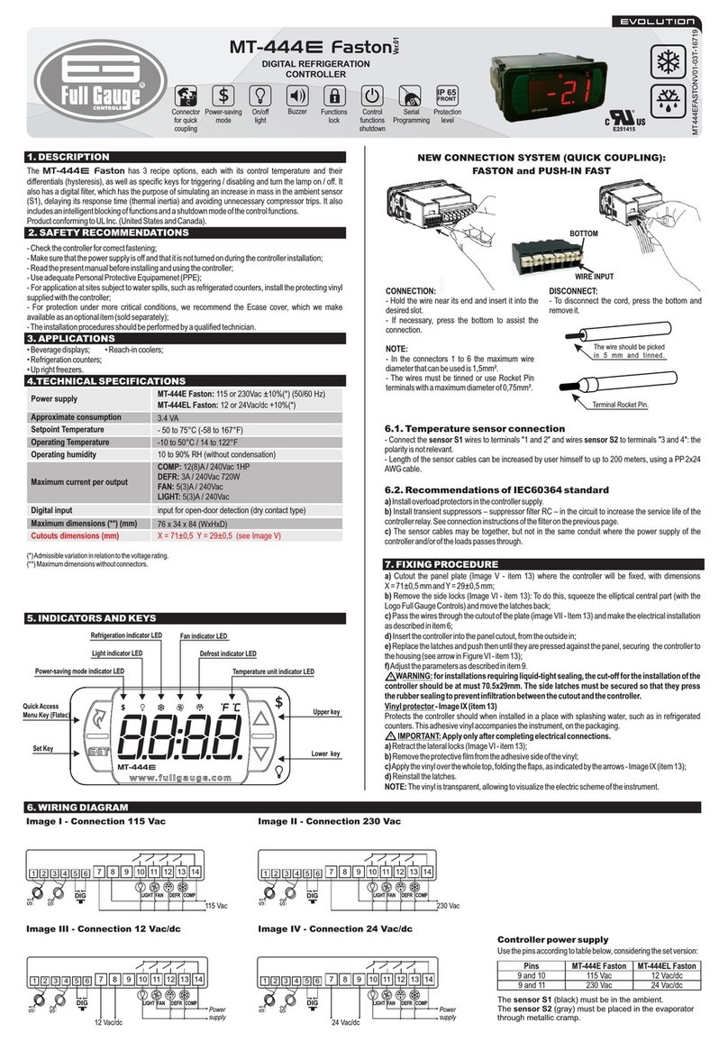
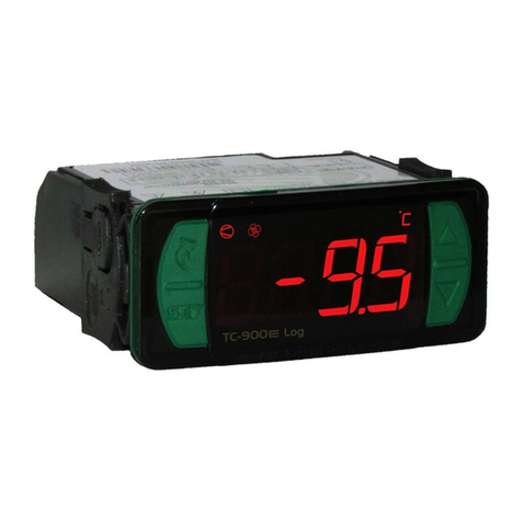
The is a digital temperature with outputs to
compressor,fananddefrost.
Beverage freezers
TC-900RG2 slim controller
Application:
- Power supply:
- Maximum load:
- Sensors:
90~264Vac (50/60 Hz)
COMP-1
FAN - 5(3)A/ 250Vac 1/8HP - Fan output
DEFR-10(3)A/250Vac1/4HP-Defrostoutput
6(8)A /250Vac1HP-Compressoroutput
S1 (Room)
S2 (Evaporator)
0 to 50°C
10 to 90% RH (without condensation)
- Operation temperature:
- Humidity operation:
CONTROLS
R
Find manuals of all line on Web:
www.fullgauge.com
Phone/Fax: +55 51 34753308
MADE IN BRAZIL
DESCRIPTION
TECHNICAL SPECIFICATIONS
Put the selector keys in the desired position and press the key for 10 seconds
until appear the indication . Release key and wait until appears the value
programmed for this function, use the key again to modify this value. After adjusted
the new value for the function wait 4 seconds. The controller will record the new
parameter and will pass to the function . Use the same procedure to modify
the value of this function. Repite this for the functions and that will be
the next to be showed in the display to be configured. After the alteration of the
parameters the display comes to the indication of temperature.
OPERATION PARAMETERS
Refrigeration time
Defrost time with the sensor of evaporator working
efrost time with the sensor of evaporator damaged
Control temperature (setpoint)
Differential of control (hysteresis)
inimum delay to restart the compressor
Low temperature or room sensor open
High temperature or room sensor in short circuit
Displacement of indication of room sensor (offset)
D
M
Parameters 00 11
12 hours
30 min.
10 min.
5.0 ºC
3.0 ºC
120 sec.
-20 ºC
45 ºC
0.0 ºC
10
30 min.
10 min.
2.0 ºC
3.0 ºC
120
-20 ºC
45 ºC
0.0 ºC
hours
sec.
01 10
6
30 min.
10 min.
-6.0 ºC
3.0 ºC
120
-20 ºC
45 ºC
0.0 ºC
hours
sec.
6
30 min.
10 min.
-1.0 ºC
3.0 °C
120
-20 ºC
45 °C
0.0 °C
hours
sec.
Item
P1
P2
P3
P4
P5
P6
P7
P8
P9
SELECTOR KEYS POSITION
Programmable parameter, indication at display
Programmable parameter, indication at display
Programmable parameter, indication at display
Programmable parameter, indication at display
Programmable parameter, indication in the display
Parametersv
Defrostonstart
Refrigeration
isualization
Whenthecontrollerisenergized,itwillappeartheparametersofconfigurationinthe
followingorder:
The controller will make defrost when energized if the temperature of the
sensor(S1)hewillbebelowof30ºCandtemperatureofthesensoroftheevaporator
(S2)belowof15ºC.
The
REFRIGERATIONTIME DEFROSTTIME SETPOINT DIFFERENTIAL
compressorturnsonandturnsoffbytemperature,accordingthevalueadjusted
in the P4 parameter (see table above) during the refrigeration time (P1). After
elapsed the time the controller will initiate a defrost cycle (if the temperature of the
sensorwill be below of 30ºC), turning offthe compressor andthe evaporator
fan.Duringthestageofrefrigeration remainsturnedononlywhilethe
compressorwillbefunctioning. evaporatorfan
room
room
PARAMETERSALTERATION
Defrost
Delay
Thedefrostwillbefinishedwhenthetemperatureintheevaporator(S2)reaches15ºC
orthetemperatureintheroom(S1)reach30ºC.Otherwise,thedefrostwill befinished
after elapsed the maximum defrost time configured (P2 or P3). During the defrost the
last temperature measured in the refrigeration cycle will be frozen in the display. The
indicationwillbedefrostedwhenthistemperaturebereachedagainor15minutesafter
theendofthedefrost.
When the instrument is energized or the temperature in the S1 sensor reaches the
setpoint (compressorturn off),thedelay(P6) starts tobecounted,preventingthatthe
compressormustberestartedinaperiodveryshort. Eventhanbytemperatureitwold
benecessarytoturnonthecompressorthedelay(P6)isrespected.
Externalselector
Theexternalselectorallows,withacombinationoftwokeys,todefinethefunctioningof
thecontrollerwithprogrammablepresets.
FUNCTIONINGDESCRIPTION
VISUAL ALARMS
KEY (ACCESS IN THE FRONT PANEL)
Tochangetherefrigerationtodefrostorvice-versa,justasimpletouchonthekey.To
visualize the temperature measured by the evaporator sensor (S2), keep pressed
thekeyfor5seconds.
TC-900RG2 slim
TC-900RG2 slim
UL-Underwriters Laboratories
