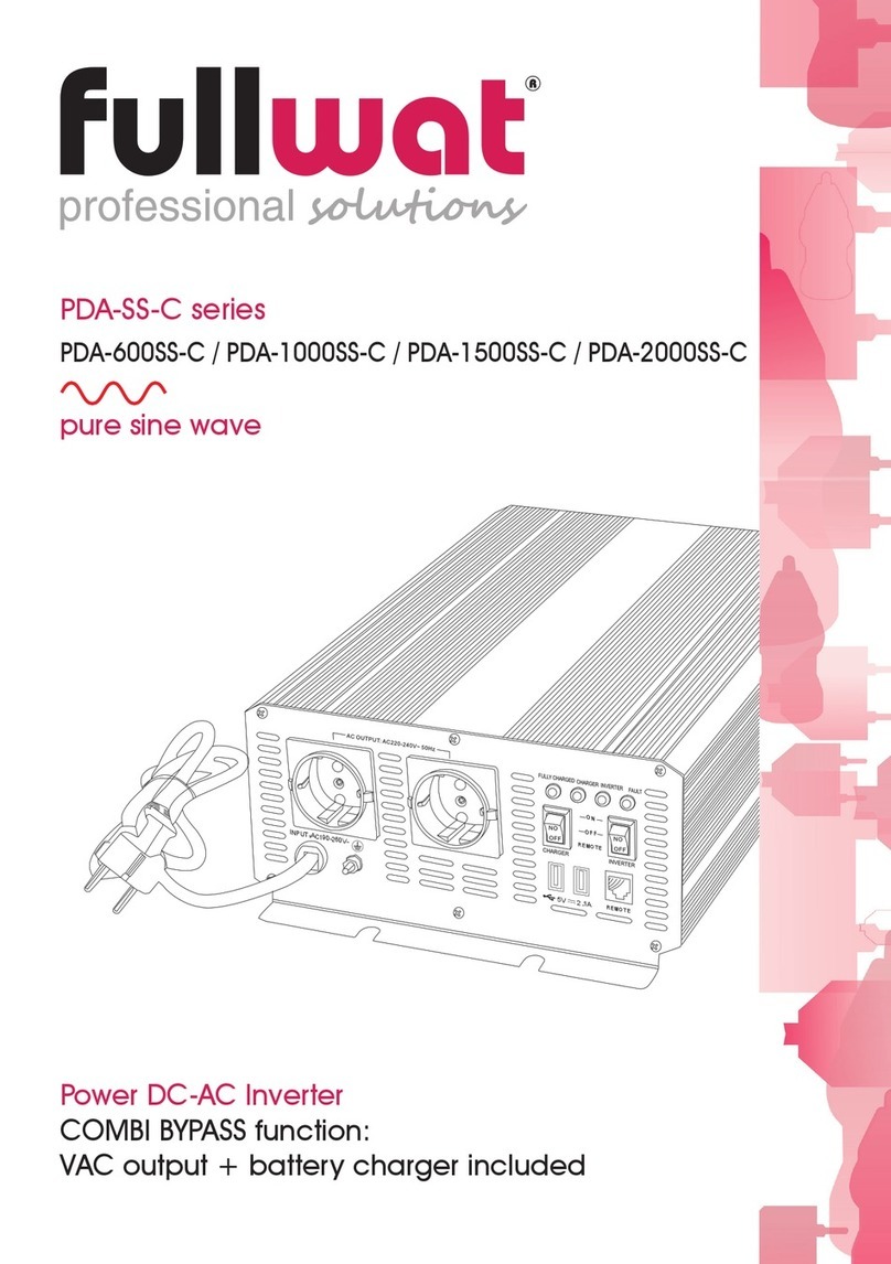
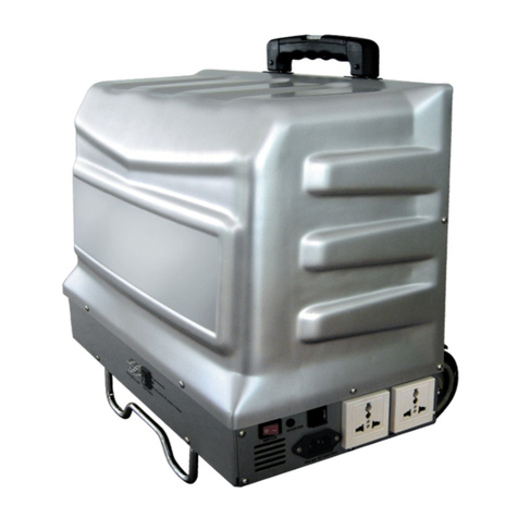
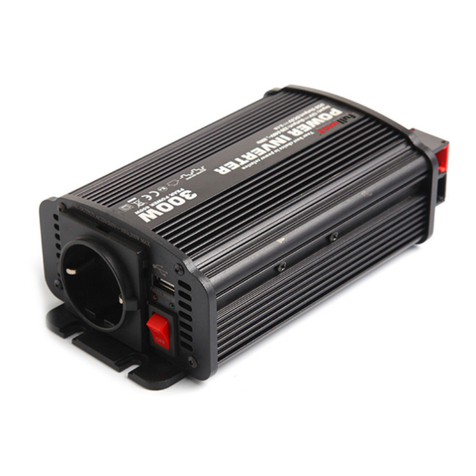
Fullwat PDA-D Series User manual

PDA-D series
Convertidor DC/AC
Power inverter DC/AC
Manual de instrucciones ........... página 2
User manual .............. page 11

- 2 -
1. INSTRUCCIONES DE SEGURIDAD IMPORTANTES
IMPORTANTE: Lea y conserve este manual de usuario para futuras consultas.
Este capítulo contiene importantes instrucciones de seguridad e instalación para nuestros inversores digitales de la serie PDA.
Cada vez, antes de utilizar el inversor de corriente, lea todas las instrucciones y marcas de precaución que se proporcionan con
el inversor y todas las secciones pertinentes de este manual.
Peligro
RIESGO DE CHOQUE ELÉCTRICO
• No exponga el inversor a la lluvia, nieve, rocío o aguas residuales. Este inversor está diseñado para su utilización en espacios
interiores.
• No opere el inversor si ha recibido un golpe fuerte, se ha caído o tiene grietas.
• No desmonte el inversor. Los condensadores internos permanecen cargados después de desconectar toda la energía.
• Desconecte tanto la alimentación de alterna como de continua del inversor antes de intentar cualquier mantenimiento,
limpieza o trabajo en cualquier circuito conectado al inversor. Vea la nota abajo.
• No opere el inversor con cableado dañado o insuficiente.
• Asegúrese de que todo el cableado esté en buenas condiciones y no sea demasiado pequeño.
El incumplimiento de estas instrucciones provocará la muerte o lesiones graves.
PELIGRO DE INCENDIO Y QUEMADURAS
• No cubra ni obstruya las aberturas de entrada de aire de ventilación ni instale en un compartimento sin espacio libre.
• No utilice cargadores de baterías sin transformador junto con el inversor debido al sobrecalentamiento.
El incumplimiento de estas instrucciones provocará la muerte o lesiones graves.
PELIGRO DE EXPLOSIÓN
• No trabaje cerca de baterías de plomo-ácido. Las baterías generan gases explosivos durante el funcionamiento normal.
• No instale ni opere en compartimentos que contengan materiales inflamables o en lugares que requieran equipos protegidos
contra ignición.
El incumplimiento de estas instrucciones provocará la muerte o lesiones graves.
NOTAS
1. Siga las instrucciones suministradas por el fabricante de la batería y el fabricante de cualquier equipo que vaya a utilizar cerca
de la batería. Revise las marcas de precaución en estos productos y en el motor.
2. El inversor contiene componentes que tienden a producir arcos o chispas.
3. La ubicaciones a evitar incluyen cualquier espacio que contenga maquinaria que funcione con gasolina, tanques de
combustible, así como juntas, accesorios u otras conexiones entre los componentes del sistema de combustible.
Precaución
RIESGO DE DAÑOS AL INVERSOR
• Nunca permita que el ácido de la batería gotee sobre el inversor al comprobar la batería o al rellenar la batería.
• Nunca coloque el inversor directamente sobre las baterías, los gases de una batería corroerán y dañarán el inversor.
• No coloque una batería encima del inversor.
El incumplimiento de estas instrucciones puede dañar la unidad y / o dañar otros equipos.
2. INTRODUCCIÓN
Los nuevos inversores de serie PDA están diseñados para brindarle potencia, facilidad de uso y fiabilidad. Estos inversores se han
mejorado respecto a nuestra anterior serie PDA, con un nuevo diseño, una tecnología mejorada y un mejor acabado. Estos
inversores tienen un display de LED digital que indica el voltaje y la potencia (V, P) constantemente.
Dedique unos minutos a leer este capítulo para familiarizarse con las principales características de funcionamiento y protección.
2.1 ENERGÍA DE CALIDAD Y FACILIDAD DE USO
Los nuevos inversores de la serie PDA han sido diseñados con características superiores, resistentes, durables y fáciles de utilizar:
la unidad es compacta, liviana y fácil de instalar. Las cargas se pueden alimentar directamente desde las salidas del inversor.
2.2 PROTECCIÓN INTEGRAL
Nuestros inversores de la serie PDA están equipados con numerosas funciones de protección para garantizar un
funcionamiento seguro y sin problemas:
• ALARMA DE BATERÍA BAJA: Le avisa si la batería se ha descargado a 10.5V o menos.
• APAGADO DE BAJO VOLTAJE DE BATERÍA: Apaga el inversor automáticamente si el voltaje de la batería cae por debajo de
9,5 voltios. Esta característica evita que la batería se descargue completamente.
•
APAGADO DE ALTO VOLTAJE DE BATERÍA:
Apaga el inversor automáticamente si el voltaje de entrada aumenta a 15.5V o más.
• APAGADO DE SOBRECARGA: apaga el inversor automáticamente si las cargas conectadas al inversor superan los límites de
funcionamiento del inversor.
• APAGADO POR SOBRETEMPERATURA: Apaga el inversor automáticamente si su temperatura interna sube por encima de un
nivel inaceptable.
• APAGADO DE SALIDA POR CORTOCIRCUITO: Apaga el inversor automáticamente si se detecta un cortocircuito en los
circuitos conectados a la salida del inversor.
• PROTECCIÓN CONTRA POLARIDAD INVERSA DE ENTRADA: El fusible se quemará si el usuario conecta la batería con la
polaridad incorrecta.

- 3 -
3. LISTADO DE MATERIALES DEL INVERSOR
El inversor se envía con los siguientes elementos: el inversor, manual de usuario, fusible de repuesto, cables de corriente continua y
un interruptor remoto de ENCENDIDO/APAGADO (ON / OFF) con cable de comunicación (opcional).
IMPORTANTE: conserve la caja y el material de embalaje en caso de que necesite devolver el inversor para su reparación.
4. CARACTERÍSTICAS DEL INVERSOR
Esta sección describe las distintas partes del inversor.
5. INSTALACIÓN DEL INVERSOR
Esta sección describe las instrucciones generales de instalación para el inversor.
IMPORTANTE: Contacte con un instalador calificado si no posee el conocimiento y la habilidad necesarios para seguir estas
instrucciones generales.
5.1 PREPARACIÓN PARA LA INSTALACIÓN
• Diseñe su sistema de energía.
• Calcule los requisitos de su batería.
• Elija un sistema de carga efectivo.
• Elija una ubicación adecuada.
• Prepare cables de sección generosa para la entrada de continua y tierra.
Tenga en cuenta que con las tensiones de continua la sección del cable influye de manera radical en la tensión final que
llega desde la batería.
El binomio batería bien cargada por encima de 13 Vdc y cable de sección adecuada es ideal para el buen
funcionamiento del aparato.
Inversores de la serie PDA 1200~2500W
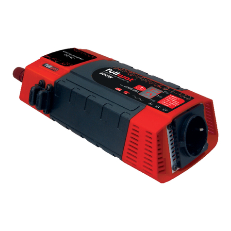
* La imagen que se muestra aquí es solo indicativa. Por favor refiérase al producto real.
Cables de corriente continua
Interruptor remoto PDA-REM-C/D de
ENCENDIDO / APAGADO (ON / OFF)
Con cable 5 mts.
No incluido. Disponible opcionalmente
Fusible
Manual de
usuario
Panel de salida alterna.
7
3 4
1
5
1
2
6
1
2
3
4
5
6
7
Tomas de corriente alterna para alimentar cargas.
Interruptor de ENCENDIDO/APAGADO (ON/OFF), enciende y apaga el inversor
Luz de fallo (roja), indica que el inversor se ha apagado debido a
sobrecarga del inversor, sobretemperatura, cortocircuito, fugas, etc.
Luz de encendido (verde), indica que el inversor está funcionando.
Puerto USB con salida de 5V 500mA o 800mA o 2.1A (opcional) para cargar
sus dispositivos.
El puerto del conector de ENCENDIDO/APAGADO remoto, se utiliza para
conectar el interruptor de ENCENDIDO/APAGADO remoto.
Panel de visualización digital, indica el voltaje de entrada de la batería y la
potencia suministrada a la carga.
Terminal de entrada de continua negativo. Siempre se conecta al terminal
negativo de la batería a través de un cable negativo de entrada de
continua (cable negro de la batería). El terminal de entrada de continua
negativo es de color negro.
Terminal de entrada de continua positivo. Siempre se conecta al terminal
positivo de la batería a través de un cable de entrada de continua positivo
(cable rojo de la batería). El terminal de entrada de continua positivo es de
color rojo.
Tornillo de conexión a tierra del chasis. Se conecta al chasis del vehículo, al
bus de conexión a tierra de continua o al bus negativo del motor o a tierra.
Aberturas de ventilación. No deben obstruirse para el correcto funcionamiento
del inversor. Cuando el inversor está montado, la abertura de ventilación en el
panel de continua no debe apuntar hacia arriba o hacia abajo.
Panel de entrada continua.
2
3 414
1
2
3
4
* La imagen que se muestra aquí es solo indicativa.
Por favor refiérase al producto real.

- 4 -
Display digital
Conexión
USB 5Vdc
Conexión
tensión alterna
Interrruptor remoto
PDA-REM-C/D
disponible opcionalmente
Toma de tierra
1-2m
Inversor
DC-AC
USB
Banco de
baterías
Diseño típico de un sistema de energía
5.2 EJEMPLO DE CONEXIÓN DEL SISTEMA DE ENERGÍA
Determine cómo va a usar su inversor y luego diseñe un sistema de
alimentación que le brinde el máximo rendimiento. La configuración
que se muestra a continuación es un diseño de sistema de alimentación
típico, solo como referencia.
5.3 REQUISITOS DE BATERÍA
El tipo de batería y el tamaño de la batería afectan fuertemente el rendimiento del inversor de corriente. Por lo tanto, debe
identificar el tipo de cargas que alimentará su inversor y cuánto las usará entre cargas. Una vez que sepa cuánta energía
necesita, le recomendamos que compre la mayor capacidad de batería posible.
IMPORTANTE: si su inversor es de 12voltios conecte el inversor a un sistema de batería de 12 voltios o batería de 12 voltios. El
inversor no funcionará en un sistema de batería de 6 voltios y se dañará cuando se conecte a un sistema de batería de más
de 12 voltios, como un sistema de batería de 24 voltios en algunos camiones o vehículos recreativos.
Si su inversor es de 24voltios conecte el inversor a un sistema de batería de 24 voltios o batería de 24 voltios. El inversor no
funcionará en un sistema de batería de 6 voltios o de 12 voltios.
Tenga presente que cualquier batería de plomo recargable debería ofrecer una tensión en vacío cercana a valores 13,4-
13,8 Vdc o similares, siempre muy por encima de los 12 Vdc nominales, si es que se halla perfectamente cargada y en
perfecto estado de salud.
Tensiones cercanas o inferiores a 12 Vdc significan un estado de carga baja o si se halla recién cargada, nos informa de
que su estado de salud no es muy bueno, lo que sugiere una sustitución.
5.4 SISTEMA DE CARGA
El sistema de carga debe ser apropiado para su instalación particular. Un sistema de carga bien diseñado asegurará
que la energía esté disponible cuando la necesite y que sus baterías permanezcan en óptimas condiciones. Una carga
inadecuada degrada el sistema y un tipo de cargador incorrecto reducirá la vida útil de la batería.
Póngase en contacto con nosotros o visite nuestro sitio web para obtener más información sobre nuestros diferentes
cargadores de batería.
6. UBICACIÓN DEL INVERSOR
El inversor solo debe instalarse en una ubicación que sea:
SECO El inversor debe instalarse en un lugar seco y no sujeto a la humedad, especialmente lluvia, rocio o salpicaduras de aguas
residuales.
FRESCO El inversor no debe exponerse a rellenos metálicos ni a ninguna otra forma de contaminación.
VENTILADO La temperatura del aire ambiente debe estar entre 0-40ºC (32-104ºF) para un mejor rendimiento.
SEGURO Las aberturas de ventilación en el inversor no deben obstruirse. Si el inversor está montado en un compartimento
ajustado, el compartimento debe ventilarse con cortes para evitar que el inversor se sobrecaliente.
CERCA DE LA BATERÍA El inversor no es un equipo protegido contra ignición, por lo que no puede instalarse en áreas que
contengan tanques de gasolina o accesorios que requieran equipo protegido contra ignición. Recomendamos que lo más
seguro es no instalar ningún tipo de equipo eléctrico, incluido el inversor, en estas áreas.
PROTEGIDO DE LOS GASES DE LA BATERÍA El inversor debe instalarse lo más cerca posible de las baterías, pero no en el mismo
compartimento para evitar la corrosión. Evite longitudes de cable excesivas y use los tamaños de cable recomendados.
Recomendamos que se instale con cables de batería dimensionados para lograr una caída de voltaje de menos del 3% en los
cables de batería bajo carga completa. Esto maximizará el rendimiento del inversor.
7. CABLES PARA LA ENTRADA DE CONTINUA Y TIERRA
Para operar de manera segura y efectiva, utilice un cableado de baja resistencia entre la batería y el inversor, porque el inversor
recibe una entrada de alta corriente desde una batería de bajo voltaje.
Tienda un cable de tierra desde el punto de tierra al tornillo de tierra del chasis en el panel de entrada continua del inversor.
Hay un cable de continua dentro del embalaje, puede usarlo en condiciones normales, si necesita una instalación más larga o
especial del sistema, puede comprar los cables en el mercado. Al comprar cables para entrada de continua y tierra:
• Utilice un cable de entrada de continua de tamaño suficiente si decide emplear un cable más largo.
• Utilice un tamaño de cable apto para el cable de tierra. Termine un extremo con un conector de anillo de tamaño adecuado.
•
Utilice cables de cobre estándar, evitando los cables de aluminio debido a su mayor resistencia. Haga que sus cables de entrada
de continua estén engarzados y terminados con conectores de anillo del tamaño apropiado en la tienda donde los compró.
Fusible o interruptor
automático DC

- 5 -
8. FUSIBLES (O DISYUNTORES)
Por cuestiones de seguridad, puede conectar un fusible de continua o un disyuntor de continua en la línea de cable positiva de
su sistema de alimentación, siga estas recomendaciones cuando compre fusibles o disyuntores.
• Seleccione un fusible o un interruptor automático con una clasificación máxima de 150 ADC.
• Determine la corriente de cortocircuito de la batería y elija un fusible para la batería que resista la corriente de cortocircuito que
puede generar la batería.
9. INSTALACIÓN DEL INVERSOR
Revise y siga las pautas de seguridad en “instrucciones de seguridad importantes” en la página antes de continuar con la
instalación.
9.1 VISIÓN GENERAL DE LOS PASOS DE INSTALACIÓN
• Montar el inversor.
• Conecte la tierra del chasis.
• Conecte los cables de continua.
9.2 MONTAJE DEL INVERSOR
1. Asegúrese de que el interruptor de ENCENDIDO / APAGADO del inversor esté en la posición de apagado (OFF).
2.
Seleccione una ubicación y orientación de montaje adecuadas. El inversor debe estar orientado de una de las siguientes
maneras:
• Horizontalmente sobre una superficie reticular. (La abertura de ventilación en el extremo de continua no debe apuntar
hacia arriba o hacia abajo).
• Sobre o debajo de una superficie horizontal.
3. Sostenga el inversor contra la superficie de montaje, marque las posiciones de los tornillos de montaje y luego retire el
inversor.
4. Haga un taladro piloto en los cuatro agujeros de montaje.
5. Sujete el inversor a la superficie de montaje con sujetadores resistentes a la corrosión del tamaño adecuado. Importante:
No instale el inversor debajo del capó del motor de un vehículo si instala el inversor en un vehículo.
9.3 CONECTE LA TIERRA AL CHASIS
1. Asegúrese de que el interruptor de ENCENDIDO / APAGADO del inversor esté en la posición de APAGADO (OFF).
2. Localice el terminal de tornillo etiquetado como tierra en el panel de entrada de continua y retire el tornillo y la arandela
de estrella.
3. Sujete el anillo del cable de tierra al terminal de tornillo del inversor y asegúrelo con la arandela de estrella y el tornillo que
ha retirado antes.
4. Conecte el otro extremo del cable de tierra al chasis del vehículo a través de un punto de tierra en el vehículo si instala el
inversor en un vehículo. O conecte el otro extremo del cable a tierra a la tierra si instala el inversor para uso doméstico.
Peligro
RIESGO DE CHOQUE ELÉCTRICO
• Nunca opere el inversor sin haber realizado una correcta puesta a tierra.
El incumplimiento de estas instrucciones provocará la muerte o lesiones graves.
9.4 CONECTE EL CABLE DE CONTINUA
IMPORTANTE: Antes de continuar, asegúrese de que sus cables de entrada de continua estén correctamente terminados con
conectores de anillo apropiados para el tamaño del cable que está utilizando. Le recomendamos que utilice el cable de
entrada de continua que viene dentro del embalaje de nuestros inversores.
1. Asegúrese de que el interruptor de ENCENDIDO / APAGADO del inversor esté en la posición de APAGADO (OFF).
2. Trabaje primero en el terminal de entrada de continua positivo del inversor: Conecte un extremo del cable de entrada de
continua positivo al terminal de entrada de continua positivo en el inversor.
IMPORTANTE: No apriete demasiado la tuerca en el terminal del inversor. Se puede dañar el terminal del inversor. Sin
embargo, las conexiones sueltas pueden causar una caída excesiva de voltaje y pueden causar cables sobrecalentados
y aislamiento derretido.
3. Conecte un portafusibles (con un fusible instalado) al otro extremo del cable positivo de la batería. Alternativamente, si usa
un interruptor automático, instale el interruptor automático en el terminal positivo de la batería.
4. Conecte el extremo con fusible del cable de entrada de continua positivo al terminal positivo de la batería.
Alternativamente, si está utilizando un interruptor automático, conecte el otro extremo del cable de entrada de continua
positivo al interruptor automático de la batería
Peligro
DAÑOS POR CONEXIÓN INVERSA DE LA POLARIDAD
• La conexión de alimentación de continua al inversor debe ser positivo a positivo y negativo a negativo.
• Una conexión inversa de la polaridad (conectar positivo y negativo) quemará el fusible interno dentro del inversor y
puede dañar el inversor.
El daño causado por una conexión inversa de la polaridad no está cubierto por la garantía.
El incumplimiento de estas instrucciones puede dañar la unidad y / o otros equipos.

- 6 -
Peligro
RIESGO DE EXPLOSIÓN Y/O INCENDIO
• Ventile completamente el compartimento de la batería antes de proceder a conectar el cable negativo de entrada de
continua a la batería. .
• Siempre es posible la presencia de gases inflamables, por lo tanto, tenga mucho cuidado.
El incumplimiento de estas instrucciones provocará la muerte o lesiones graves.
5. Trabaje ahora en el terminal de entrada de continua negativo del inversor, conecte un extremo del cable de entrada de
continua negativo al terminal de entrada de continua negativo en el inversor.
6. Conecte el otro extremo del cable negativo de entrada de continua al terminal negativo de la batería. Si ha instalado un
interruptor selector de batería, desactívelo cuando realice la conexión para evitar chispas.
NOTA: Esta es la última conexión de cable, es normal que salten chispas cuando realiza la conexión a la batería sin un
interruptor selector de batería. Si ha instalado un interruptor selector de batería, úselo para seleccionar una de las baterías
o bancos de baterías (se prefiere el banco de la casa sobre el banco de arranque).
7. Mueva el interruptor de ENCENDIDO / APAGADO del inversor a la posición ENCENDIDO (ON). La luz de encendido (verde)
debe iluminarse, indicando que el inversor está listo para funcionar.
10.FUNCIONAMIENTO DEL INVERSOR
Esta sección explica cómo operar el inversor de manera eficiente y efectiva:
• Proporciona procedimientos para operar el inversor desde el panel frontal.
• Discute los límites de operación y las cargas del inversor
• Discute la frecuencia de carga de la batería
• Proporciona información sobre el mantenimiento de rutina.
NOTA: La eficiencia de potencia de salida del inversor es diferente cuando el voltaje de entrada es diferente
Peligro
PELIGRO DE CHOQUE ELÉCTRICO
• El interruptor de ENCENDIDO / APAGADO del inversor no desconecta la energía de la batería del inversor. Debe desconectar la
alimentación de alterna y de continua antes de trabajar en cualquier circuito conectado al inversor.
El incumplimiento de estas instrucciones provocará la muerte o lesiones graves.
10.1 ENCENDIDO Y APAGADO DEL INVERSOR
El interruptor de ENCENDIDO / APAGADO en el panel frontal del inversor es el interruptor de ENCENDIDO / APAGADO principal que
enciende y apaga el circuito de control en el inversor.
Para encender y apagar el inversor desde su panel frontal:
• Mueva el interruptor de ENCENDIDO / APAGADO a la posición de encendido (ON) para encender el inversor.
• Mueva el interruptor de ENCENDIDO / APAGADO a la posición de apagado (OFF) para apagar el inversor.
Cuando el interruptor está apagado, el inversor extrae una corriente muy baja de la batería.
Para encender y apagar el inversor desde el interruptor remoto:
•
Asegúrese de que el interruptor principal de ENCENDIDO / APAGADO del panel frontal esté en la posición de encendido (ON).
• Mueva el interruptor remoto ON / OFF a la posición de encendido (ON) para encender el inversor.
• Mueva el interruptor remoto ON / OFF a la posición de apagado (OFF) para apagar el inversor.
Cuando el interruptor remoto está apagado, el inversor extrae una corriente muy baja de la batería.
IMPORTANTE: El inversor extrae una corriente de la batería con el interruptor principal encendido y sin carga conectada.
Si el interruptor principal se deja encendido, incluso sin cargas, el inversor finalmente descargará la batería. Para evitar la
descarga innecesaria de la batería, apague el inversor cuando no lo esté utilizando.
11.
DISPLAY LED DIGITAL
Los inversores de la serie PDA combinan un diseño industrial innovador con un display LED interactivo avanzado.
Esto proporciona al usuario información instantánea sobre el voltaje de entrada y la potencia de carga de salida. Estos nuevos
inversores proporcionan una forma conveniente y potente de acceder a la alimentación de alterna.
El inversor digital proporciona instantáneamente información sobre:
• El voltaje restante en la batería.
• La potencia que está consumiendo una carga.
1. Cuando el dato que se muestran después de V es 12, significa que el voltaje de entrada de la batería es de 12 VCC.
2. Cuando el dato que se muestran después de P es 10, si por ejemplo utiliza nuestro inversor de 1200 W, significa que su
dispositivo está consumiendo 120 W. (Los datos P indican el porcentaje de carga del inversor).
V 12 P 10

- 7 -
12.
CONEXIÓN DE VARIAS CARGAS A LA VEZ
Si va a operar varias cargas desde el inversor, encienda las cargas de una en una después de encender el inversor.
Encender las cargas por separado ayuda a garantizar que el inversor no tenga que entregar la corriente de arranque de todas las
cargas a la vez, y ayudará a prevenir una desconexión por sobrecarga.
La potencia de salida que el inversor puede entregar en régimen continuo (en vatios) es la indicada en la etiqueta del inversor
(por ejemplo, la etiqueta indica 1200W continuos en un inversor de 1200W). La potencia nominal se aplica a cargas resistivas
como luces incandescentes.
Voltaje de entrada: los rangos de voltaje de entrada permitidos de nuestro inversor se muestran en la siguiente tabla:
13.CARGAS EN EL INVERSOR
El inversor operará la mayoría de las cargas de alterna dentro de su potencia nominal. Sin embargo, algunos electrodomésticos
y equipos pueden ser difíciles de operar, y otros pueden dañarse si intenta operar con el inversor. Lea atentamente “cargas de
sobretensión elevada” y “cargas problemáticas”.
13.1
CARGAS DE SOBRETENSION ELEVADA
Algunos motores de inducción utilizados en congeladores, bombas y otros equipos operados por motor requieren altas
corrientes de arranque para arrancar. Es posible que el inversor no pueda arrancar algunos de estos motores; a pesar de
que su consumo de corriente nominal está dentro de los límites del inversor. El inversor normalmente arrancará motores de
inducción monofásicos.
13.2 CARGAS PROBLEMATICAS
1. Algunos equipos pueden no funcionar bien o ser dañados por la salida de onda sinusoidal modificada del inversor.
2. Algunos electrodomésticos, incluidos los tipos enumerados a continuación, pueden no funcionar bien o dañarse si están
conectados al inversor.
• La electrónica que modula las señales de RF (radiofrecuencia) en la línea de CA no funcionará bien o puede dañarse.
• Los controladores de velocidad que se encuentran en algunos ventiladores, herramientas eléctricas, electrodomésticos
de cocina y otras cargas pueden no funcionar bien.
• Algunos cargadores para pequeñas baterías recargables.
• Lámparas de halogenuros metálico (HlD). Si no está seguro de alimentar cualquier dispositivo con el inversor, póngase
en contacto con el fabricante del dispositivo.
13.3
CONEXIÓN DE APARATOS AL INVERSOR
Dado que fluye una cantidad regular de corriente alterna entre el inversor y sus dispositivos, se pueden utilizar cables de
extensión comúnmente disponibles para conectar el inversor a sus dispositivos. Si sus electrodomésticos se conectarán a una
distancia considerable del inversor, es mucho más práctico y menos costoso alargar el cableado de alterna que alargar el
cableado de continua.
14.
MANTENIMIENTO DE RUTINA
Mantener el inversor requiere un mantenimiento mínimo para mantener su inversor funcionando correctamente, periódicamente
debe:
• Limpie el exterior de la unidad con un paño húmedo para evitar la acumulación de polvo y suciedad.
• Asegúrese de que los cables de continua seguros y que los tornillos y tuercas estén apretados.
• Asegúrese de que las aberturas de ventilación en el panel de continua y la parte inferior del inversor no estén obstruidas.
15.RECARGA DE LAS BATERÍAS
Cuando sea posible, recargue las baterías cuando estén descargadas en un 50% o antes. Esto les da a las baterías un ciclo de
vida mucho más largo que la recarga cuando están más descargadas.
Nuestro inversor tiene un apagado de baja tensión de la batería de alrededor de 10 V. Con cargas moderadas a pesadas, esto
protegerá contra la descarga excesiva de la batería. Si el inversor funciona solo con cargas ligeras, es recomendable recargarlas
antes de que se alcance el punto de apagado de bajo voltaje del inversor.
Para obtener más información sobre el mantenimiento de las baterías, consulte al fabricante de su batería.
Para obtener información sobre nuestros cargadores de batería, contáctenos.
Condiciones de uso Rango de voltaje Comentario
Normal 9,5~16V ---
Rendimiento óptimo 12~13V ---
Alarma de baja tensión 11V o menos Suena la alarma audible de batería baja
Desconexión por baja
tensión menos de 10V
El inversor se apaga para protegerse del voltaje de entrada excesivo
(nota: aunque el inversor incorpora protección contra sobrevoltaje,
aún puede dañarse si el voltaje de entrada excede los 16 voltios. El
inversor se apaga para proteger la batería de una descarga excesiva.

- 8 -
16.
CÁLCULO DE LA CAPACIDAD DE LA BATERÍA
El tiempo de respaldo de la batería depende de la capacidad de batería (Ah) y la potencia de sus electrodomésticos (W).
El método para calcular el tiempo de operación es:
Capacidad de la batería (Ah) x voltaje de entrada / potencia de carga (W).
Por ejemplo: Voltaje de entrada = 12V
Carga de potencia = 600W
(150Ah X 12V) / 600W = 3H
17.
SOLUCIÓN DE PROBLEMAS
Esta sección describe los problemas más comunes que puede encontrar con el funcionamiento del inversor junto con las
soluciones. Si encuentra problemas distintos a los descritos en esta sección, comuníquese con el centro de atención al cliente.
17.1
PROBLEMAS COMUNES
Zumbido en equipos de audio
Algunos sistemas estéreo económicos pueden emitir un zumbido de sus altavoces cuando se opera el inversor. Esto ocurre
porque la fuente de alimentación en el sistema de audio no filtra adecuadamente la onda sinusoidal modificada producida
por el inversor. La única solución es utilizar un sistema de sonido que tenga una fuente de alimentación de alta calidad.
Recepción de televisión
Cuando el inversor está funcionando, puede interferir con la recepción de televisión en algunos canales. Si se produce
interferencia, intente lo siguiente:
1. Asegúrese de que el tornillo de tierra de chasis en la parte posterior del inversor esté firmemente conectado al
sistema de tierra de su vehículo u hogar.
2. Asegúrese de que la antena de televisión proporcione una señal adecuada (“libre de nieve”) y que esté utilizando
un cable de buena calidad entre la antena y el televisor.
3. Mantenga los cables entre la batería y el inversor lo más cortos posible y gírelos junto con seis o siete giros por
metro (esto minimiza la interferencia radiada de los cables).
4. Mueva el televisor lo más lejos posible del inversor.
5. No opere cargas de alta potencia con el inversor cuando el televisor está encendido.
Peligro
Peligro de choque eléctrico.
• No desmonte el inversor. No contiene piezas reparables por el usuario.
El incumplimiento de estas instrucciones provocará la muerte o lesiones graves.
17.2
TABLA 1 REFERENCIA DE SOLUCIÓN DE PROBLEMAS
Problema Causa posible Solución
Baja tensión de
salida
Está utilizando un voltímetro que no
puede leer con precisión el voltaje
de la onda sinusoidal modificada.
Bajo voltaje de entrada y la carga
está cerca de la potencia máxima
permitida.
Use un voltímetro de lectura de verdadero valor eficaz
como el Fluke87.
Verifique las conexiones y el cable para ver si la batería
está completamente cargada.
Recargue la batería si está baja.
Reducir la carga.
No hay voltaje de
salida.
Tanto la luz de
encendido como
la luz de falla
están apagadas.
El inversor está apagado.
No hay energía para el inversor.
El inversor podría haberse
conectado con polaridad de
entrada invertida
Encienda el inversor.
Verifique el cableado al inversor y el interruptor selector de
batería (si está instalado).
El inversor probablemente ha sido dañado. Devuelva la
unidad, el daño causado por la polaridad inversa no está
cubierto por la garantía.
No hay voltaje
de salida. La
luz de fallo está
encendida
Bajo voltaje de entrada.
Alto voltaje de entrada.
Desconexión por
sobretemperatura.
Unidad sobrecargada.
La salida está en cortocircuito
Recargue la batería, verifique las conexiones y el cable.
Asegúrese de que el inversor esté conectado a una batería
correcta (inversor de 12V para batería de 12V, inversor de
24V para batería de 24V).
Deje que la unidad se enfríe.
Reduzca la carga si se requiere una operación continua.
Mejore la ventilación. Asegúrese de que las aberturas de
ventilación del inversor no estén obstruidas.
Reducir la temperatura ambiente.
Reducir la carga.
Asegúrese de que la carga no exceda la capacidad de
salida del inversor.
Elimine el cortocircuito
.
La alarma de
batería baja
permanece
encendida
Mal cableado de continua, mal
estado de la batería
Utilice el tamaño y la longitud de cable adecuados y
realice conexiones sólidas.
Cargue la batería.
Instale una batería nueva

- 9 -
18.
ESPECIFICACIONES
18.1
ESPECIFICACIONES ELÉCTRICAS
18.2
ESPECIFICACIONES FÍSICAS
19.INSTRUCCIONES DE ELIMINACIÓN
EQUIPO ELECTRÓNICO PARA EL HOGAR: Si ya no desea utilizar este dispositivo, llévelo al punto de recolección correspondiente o
entréguelo a un lugar público de reciclaje para equipos electrónicos viejos. Los equipos electrónicos no deben desecharse bajo
ninguna circunstancia de la misma manera que los desechos domésticos normales (vea el símbolo del cubo de basura tachado
a continuación).
INSTRUCCIONES DE ELIMINACION ADICIONALES: Entregue el electrodoméstico en condiciones que permitan un reciclaje y
eliminación seguros. Retire todas las baterías del aparato de antemano y evite que se dañen los recipientes de líquidos. El equipo
electrónico puede contener sustancias nocivas. El uso incorrecto o el mal funcionamiento causado por un daño puede afectar
negativamente la salud humana y dañar el medio ambiente durante el reciclaje.oper use or malfunction caused by damage
may adversely affect human health and harm the environment during recycling.
Modelo PDA1200 PDA1500 PDA2000 PDA2500
Máxima potencia de salida contiuna 1200W 1500W 2000W 2500W
Máxima potencia de salida de pico 2400W 3000W 4000W 5000W
Rango de temperatura de
funcionamiento 0~40ºC (32-104ºF)
Rango de voltaje de salida 220~240VAC
Forma de la onda de salida Onda senoidal modificada
Frecuencia de salida 50Hz±3
Salida del display digital V, P constante (voltaje y potencia)
Puerto USB 5V 500mA
Rango de voltaje de entrada
12V
9,5~15V
24V
19~30V
48V
38~60V
Alarma de batería baja 10,5±0,5V 21±1V 42±2V
Desconexión por batería baja 9,5±0,5V 19±1V 38±2V
Desconexión por sobretensión 15±0,5V 30±1V 60±2V
Protección contra cortocircuitos Desconexión y cortar la salida
Protección contra sobretemperatura Desconexión y cortar la salida
Protección contra inversión de
polaridad Por fusible interno abierto
Eficiencia óptima ≥90% ≥85%
Consumo de corriente sin carga ≤0,7A ≤0,85A ≤1,1A ≤1,35A
Fusible reemplazable ¡Apaque el inversor antes de reemplazar el fusible! El fusible
reemplazado debe tener las mismas especificaicones que el original.
Control remoto
Opcional, si elige el inversor con control remoto, entonces hay un
interrruptor remoto con cable de comunicación de 5m dentro del
embalaje.
Modelo PDA1200 PDA1500 PDA2000 PDA2500
Dimensiones (mm)
100 x 230 x 270 100 x 230 x 270 100 x 230 x 330 100 x 230 x 330
Peso(g)
2550 2900 3960 4220
Nota: Las especificaciones están sujetas a cambios sin previo aviso.

- 10 -
20.GARANTÍA Y ACUERDOS DE SERVICIO
Esta garantía cubre solo defectos de fabricación. El aparato no debe modificarse de ninguna manera con respecto a su
forma o a sus funciones, internas o externas.
También se considerará anulada la garantía si el aparato ha sufrido la intervención de personal no autorizado o ajeno a la
organización de la marca.
Esta garantía no se aplica en caso de uso incorrecto; uso que cae más allá del uso normal como se indica en el manual del
usuario o si hay daños causados por fuerza mayor (por ejemplo, desastre natural).
La garantía es sólo aplicable a este aparato y no se reparará ningún aparato o instalación dañada como consecuencia del
uso del mismo.
Solo se aceptarán aparatos limpios e intactos para la reparación con garantía y sin garantía. La garantía cubre piezas y mano
de obra necesarias para resolver el problema.
Este dispositivo está considerado como un “bien o producto industrial” que necesita de la intervención de un profesional
conocedor de los detalles y parámetros de instalación.
No se trata de un “bien de consumo” apto para ser instalado por un usuario final no profesional. Si usted como tal, decide
instalar el aparato por su cuenta, por favor tenga en cuenta este detalle y en lo que una instalación no profesional representa
a los efectos de aplicación de la garantía.
La garantía de este dispositivo es de 12 meses a partir de la fecha de compra. Ésta, es una garantía limitada y voluntaria,
ofrecida por la marca y siguiendo la legislación pertinente en lo que respecta a “productos o bienes industriales”.
Para hacer efectiva esta garantía es necesario presentar factura fechada original del distribuidor con todos los datos de éste y
el número de serie del dispositivo.
Número de modelo ....................................................
Fecha de compra: .....................................................
Sello y firma del concesionario: ..................................
Fecha de reclamo de garantía:.................................
Defectos observados: .................................................

- 11 -
1. IMPORTANT SAFETY INSTRUCTIONS
IMPORTANT: Read and save this owner’s guide for future reference.
This chapter contains important safety and installation instructions for our PDA series digital inverters. Each time, before using the
power inverter, read all instructions and cautionary marking on provided with inverter and all appropriate sections of this guide.
Danger
ELECTRICAL SHOCK HAZARD
• Do not expose the inverter to rain, snow, spray, or bilge water. This inverter is designed for indoor use only.
• Do not operate the inverter if it has received a sharp blow, been dropped, has cracks.
• Do not disassemble the inverter. Internal capacitors remain charged after all power is disconnected.
•
Disconnect both AC and DC power from the inverter before attempting any maintenance, cleaning or working on any circuits
connected to the inverter. See note below.
• Do not operate the inverter with damaged or substandard wiring.
• Make sure that all wiring is in good condition and not undersized.
Failure to follow these instructions will result in death or serious injury.
FIRE AND BURN HAZARD
• Do not cover or obs
truct the air intake vent openings and / or install i n a zero-clearance compartment.
• Do not use transformerless battery chargers in conjunction
with the inverter due to avemeating.
Failure to follow these instructions will result in death or serious injury.
EXPLOSION HAZARD
• Do not work in the vicinity of lead-acid batteries. Batteries generate explosive gases during normal operation.
• Do not install and /or operate in compartments containing flammable materials or in locations that require ignition-protected
equipment.
Failure to follow these instructions will result in death or serious injury.
NOTES
1. Follow those instructions published by the battery manufacturer and the manufacturer of any equipment you intend to use in the
vicinity of the battery. Review cautionary markings on these products and on the engine.
2. The inverter contains components which tend to produce arcs or sparks.
3. Avoiding locations include any space containing gasoline-powered machinery, fuel tanks, as well as joints, fittings, or other
connections between components of the fuel system.
Caution
RISK OF DAMAGE TO THE INVERTER
• Never allow battery acid to drip on the inverter when reading gravity, or filling battery.
• Never place the inverter unit directly above batteries, gases from a battery will corrode and damage the inverter.
• Do not place a battery on top of the inverter.
Failure to follow these instructions can damage the unit and/or damage other equipments.
2. INTRODUCTION
The new PDA series inverter are designed to give you quality power, ease of use, and reliability. These inverters have been upgraded
from our previous PDA series, it is with new design case, improved technology and better workmanship. The PDA series digital
inverter with digital LED, it indicates the voltage and power (V, P) constantly.
Please take a few moments to read this chapter to familiarize you with the main performance features and protection features.
2.1 QUALITY POWER & EASE OF USE
The PDA series inverter have been superior features, rugged durability and ease of use: The unit is compact, light weight, and
easy to install. Loads can be powered directly from inverter’s outlets.
2.2 COMPREHENSIVE PROTECTION
Our PDA series inverter are equipped with numerous protection features to guarantee safe and trouble-free operation:
• LOW BATTERY ALARM: Alerts you if the battery has been discharged to 10.5V or lower.
• LOW BATTERY VOLTAGE SHUTDOWN: Shuts the inverter down automatically if the battery voltage drops below 9.5 volts. This
feature protects the battery from being completely discharged.
• HIGH BATTERY VOLTAGE SHUTDOWN: Shuts the inverter down automatically if the input voltage rises to 15.5 volts or higher.
• OVER LOAD SHUTDOWN: Shuts the inverter down automatically if the loads connected to the inverter exceed the inverter’s
operating limits.
• OVER TEMPERATURE SHUTDOWN: Shuts the inverter down automatically if its internal temperature rises to above an
unacceptable level.
• OUTPUT SHORT CIRCUIT SHUTDOWN: Shuts the inverter down automatically if a short circuit is detected in the circuitry
connected to the inverter’s output.
• INPUT REVERSE POLARITY PROTECTION: The fuse shall blow if user connect the battery in wrong polarity.

- 12 -
3. INVERTER MATERIAL LIST
The inverter ships with the following items: inverter unit, manual, spare fuse, DC cables and one ON/OFF remote switch with
communication cable (optional).
IMPORTANT: keep the carton and packing material in case you need to return the inverter for servicing.
4. INVERTER FEATURES
This section describes the different parts of the inverter.
5. INVERTER INSTALLATION
This section describes general installation instructions for the power inverter.
IMPORTANT: Use a qualified installer if you do not possess the knowledge and skill necessary to follow these general instructions.
5.1 PREPARE FOR INSTALLATION
• Design your power system.
• Calculate your battery requirements.
• Choose an effective charging system.
• Choose an appropriate location.
• Use suitable enough size wires for DC poles and ground connections.
Take into account that size wires affect to final voltage reached to inverter input from battery.
Best performances status is achieved with a combination of full charged and healthy battery plus suitable size connection
wires.
Inverter unit for MS & MSD Series 1000-3500W
* The image shown here is indicative only,
pls refer to the actual product.
DC cables
Remote control PDA-REM-C/D
ON-OFF remote switching.
5 mt cable included.
Optional part to be ordered separately
Fuse
User Manual
Output AC panel.
7
3 4
1
5
1
2
6
1
2
3
4
5
6
7
AC outlets are used to power loads.
ON/OFF Switch turns the Inverter on and off.
Fault light (red) indicates that the inverter has shutdown due to
inverter overload, over temperature, short circuit, and leakage, etc.
or failure status.
Power light (green) indicates the inverter is operating.
USB port with output DC5V 500mA or 800mA or 2.1A (optional) for
charging for your appliance.
Remote ON/OFF connector port is used for connecting the ON/OFF
remote switch.
Digital display panel indicates the input voltage from battery and
the rate of loaded power.
Input DC panel.
2
3 414
1
2
3
4
Negative DC Input terminal always connects to the negative
terminal of the battery via a negative DC input cable (black battery
cable). The negative DC input terminal is colored black.
Positive DC Input terminal always connects to the positive terminal
of the battery via a positive DC input cable (red battery Cable). The
positive DC input terminal is colored red.
Chassis ground screw connects to vehicle chassis, DC grounding
bus or engine’s negative bus or grounding the earth.
Ventilatlon openings must not be obstructed for the proper
operation of the inverter. When the inverter is mounted, then
ventilation opening on the DC panel must not point up or down.
* The image shown here is indicative only, pls refer to the actual product.

- 13 -
5.2 POWER SYSTEM CONNECTION EXAMPLE
Determine how you are going to use your inverter then design a power
system that will give you maximum performance. The configuration
shownbelow is some typical power system design, only for reference.
5.3 BATTERY REQUIREMENTS
Battery type and battery size strongly affect the performance of the power inverter. Therefore, you need to identify the type
of loads your inverter will be powered and how much you will be using them between charges. Once you know how much
power your need. We recommend that you purchase as much battery capacity as possible.
IMPORTANT: Connect the inverter to a 12-volt battery or 12-volt battery bank system. The inverter will not work on 6-volt battery
system and will be damaged when connected to a higher-than-12-volt battery system such as a 24-volt battery system in
some trucks or recreational vehicles.
Be awared to watch service voltage from your battery system. Unloaded battery voltage should be 13,4-13,8 Vdc always,
over 12 Vdc in any case if your battery is fully charged and in healthy condition.
Lower voltages such as ≤12 vdc after full charging processing or after working period usage will determinate battery end of
life ready to change by a new one.
5.4 CHARGING SYSTEM
The charging system must be appropriate for your particular installation. A well-designed charging system will ensure that
power is available when you need it and that your batteries remain in top condition. Inadequate charging degraded system
performance and the wrong type of charger will reduce battery life.
Contact with us or visit our website to find more information about our different battery chargers.
6. INVERTER LOCATION
The Inverter power inverter must only be installed in a location that is:
DRY The inverter must be installed in a dry location and not subject to moisture especially rain, spray, or splashing bilge water.
COOL The inverter should not be exposed to metal fillings or any other form of contamination.
VENTILATED The ambient air temperature should be between 0-40ºC (32-104”F) for best performance.
SAFE Ventilation openings on the inverter must not be obstructed. If the inverter is mounted in a tight fitting compartment, the
compartment must be ventilated with cut-outs to prevent the inverter from overheating.
CLOSE TO BATTERY The inverter is not ignition-protected equipment, so it cannot be installed in areas containing gasoline tanks or
fittings which require ignition protected equipment. We recommend that it is safest not to install any kind of electrical equipment
including the inverter in these areas.
PROTECTED FROM BATTERY GASES The inverter should be installed as close as possible to the batteries, but not in the same
compartment to prevent corrosion. Avoid excessive cable lengths and use the recommended wire sizes. We recommend that
install with sized battery cables to achieve less than 3% voltage drop on battery cables under full load. This will maximize the
performance of the inverter.
7. CABLES FOR DC INPUT AND GROUND
To operate safely and effectively, use low- resistance wiring between the battery and the inverter because the inverter receives
high-current input from a low-voltage battery.
Run a chassis ground cable from the grounding point to chassis ground screw on the inverter’s DC panel.
There is spare DC cable inside of packing, you can use it for normal connection, if you need longer or special system installation,
you can buy the cables from market. When purchasing cables for DC input and ground:
• Use the enough size DC input cable if you use longer cable.
• Use a matching cable size for ground cable. Terminate one end with an appropriately-sized ring connector.
• Use standard copper wires, avoiding aluminum wires due to their higher-resistance rating. Have your DC input cables crimped
and terminated with appropriately sized ring connectors at the store of purchase.
Digital display
DC
loads
AC loads
Remote control
(opcional)
Earth stake
1-2m
Power
inverter
USB
Batteries
bank
Fuse or
Circuit breaker
Typical power system designs

- 14 -
8. FUSES (OR CIRCUIT BREAKERS)
For safety concern, you can connect a DC-rated fuse or a DC-rated circuit breakers on the positive cable line in your power
system, follow these recommendations when you purchasing fuses or circuit breakers.
• Select a fuse or circuit breaker with a maximum rating of 150 Ade.
• Determine the short-circuit current rating of the battery and choose a battery fuse that withstand the short circuit current that may
be generated by the battery.
9. INSTALL THE INVERTER
Review and follow the safety guidelines in “important safety instruction” on page before proceeding with installation.
9.1 OVERVIEW OF INSTALLATION STEPS
• Mount the inverter.
• Connect the chassis ground.
• Connect the DC cables.
9.2 MOUNT THE INVERTER
1. Make sure the inverter’s ON/OFF switch is in the off position.
2.
Select an appropriate mounting location and orientation. The inverter must be oriented in one of the following ways:
• Horizontally on a vertical surface. (The ventilation opening on the DC end must not point up or down.)
• On or under a horizontal surface
3. Hold the inverter against the mounting surface, mark the positions of the mounting screws, and then remove the inverter.
4. Pilot drill the four mounting holes.
5. Fasten the inverter to the mounting surface using corrosion-resistant fasteners proper sized. Important: Do not mount the
inverter under the engine hood of a vehicle if you install the inverter on vehicle.
9.3 CONNECT THE CHASSIS GROUND
1. Make sure the inverter’s ON/OFF switch is in the OFF position.
2. Locate the screw terminal labeled chassis ground on the DC panel and remove the chassis ground screw and star washer.
3. Attach the ground cable’s ring connector to the screw terminal on the inverter and secure with the star washer and chassis
ground screw.
4. Attach the other end of the ground cable to the vehicle chassis via a grounding point on the vehicle if you install the
inverter in vehicle. Or attach the other end of the ground cable to the earth If you install inverter for household use.
Danger
ELECTRICAL SHOCK HAZARD
• Never operate the inverter without properly connecting the chassis ground.
Failure to follow these instructions will result in death or serious injury.
9.4 CONNECT THE DC CABLE
IMPORTANT: Before proceeding, make sure that your DC input cables are properly terminated with ring connectors appropriate
for the size of the cable you are using. We advise you use the DC input cable inside of our inverters packing.
1. Make sure the inverter’s ON/OFF switch is in the off position .
2. Working on the inverter’s positive DC input terminal first, attach one end of the positive DC input cable to the positive DC
input terminal on the inverter.
IMPORTANT: Do not over tighten the nut on the inverter terminal. Damage to the inverter terminal may result. However, loose
connections can cause excessive voltage drop and may cause overheated wires and melted insulation.
3. Attach a fuse holder (with an installed fuse) to the other end of the positive battery cable. Alternatively, if you use a circuit
breaker, install the circuit breaker on the positive terminal of the battery.
4. Attach the fused end o
n the positive DC input cable to the positive terminal of the battery. Alternatively, if you are using a
circuit breaker, attach the other end of the positive DC input cable to the circuit breaker on the battery.
Danger
DAMAGE FROM A REVERSE POLARITY CONNECTION
• DC power connection to the inverter must be positive to positive and negative to negative.
• A reverse polarity connection (connecting positive to negative) will blow the internal fuse inside the inverter and can cause
damage to the inverter.
Damage caused by a reverse polarity connection is not covered by the warranty. Failure to follow these instructions can
damage the unit and/or damage other equipment.

- 15 -
Danger
EXPLOSION AND / OR FIRE HAZARD
• Thoroughly ventilate the battery compartment before proceeding to connect the negative DC input cable to the battery.
• It is always possible that flammable fumes are preventing, so exercise extreme caution.
Failure to follow these instructions will result in death or serious injury.
5. Working on the inverter’s negative DC input terminal, attach one end of the negative DC input cable to the negative DC
input terminal on the inverter.
6. Attach the other end of the negative DC input cable to the negative terminal of the battery If you have installed a battery
selector switch, set it to off when making the connection to prevent sparking.
NOTE: This is last cable connection, spark is normal when you make the connection to the battery without a battery selector
switch. If you have installed a battery selector switch, use it to select one of the batteries or battery banks (house bank
preferred over start bank).
7. Move the inverter’s ON/OFF switch to the ON position. The power light should illuminate, indicating that the inverter is ready
for operation.
10.INVERTER OPERATION
This section explains how to operate the inverter efficiently and effectively:
• Gives procedures for operating the inverter from the front panel.
• Discusses operating limits and inverter loads.
• Discusses battery charging frequency.
• Provides information about routine maintenance.
NOTE: The inverter’s output power efficiency is different when input voltage different.
Danger
ELECTRICAL SHOCK HAZARD
• The inverter’s ON/OFF switch does not disconnect DC battery power from the inverter. You must disconnect AC and DC power
before working on any circuits connected to the inverter.
Failure to follow these instructions can result in death or serious injury.
10.1 TURNING THE INVERTER ON AND OFF
The ON/OFF switch on the inverter’s front panel is the main ON/OFF switch that turns the control circuit in the inverter ON and OFF.
To turn the inverter ON and OFF from it’s front panel:
• Move the ON/OFF switch to the ON position to turn the inverter on.
• Move the ON/OFF switch to the OFF position to tum the inverter off.
When switch is off, the inverter draws a very low current from the battery.
To turn the inverter ON and OFF from the remote switch:
• Make sure the main ON/OFF switch on the front panel is turned ON.
• Move the remote ON/OFF switch to the ON position to turn the inverter ON.
• Move the remote ON/OFF switch to the OFF position to turn the inverter OFF.
When the remote switch is off, the inverter draws a very low current from the battery.
IMPORTANT: The inverter draws a current from the battery with the main ON/OFF switch turned on and no load connected. If
the main switch is left on, even with no loads the inverter will eventually discharge the battery. To prevent unnecessary battery
discharge, turn the inverter off when you are not using it.
11.
DISPLAY LED INDICATION FUNCTION
The PDA series inverter combines innovative industrial design with an advanced interactive LED display.
This provides the user with instant feedback on input voltage and output loading power. These new digital inverters provide a
convenient and powerful way to access AC power.
Digital inverter instantly provides information on:
• The amount of voltage remaining in the battery
• The amount of wattage an application is drawing.
1. When display the data after the V is 12, it means that the input voltage from the battery is 12V dc.
2. When display the data after the P is 1O, e.g.: if you use our 600W inverter, it means that your appliance loaded is 60W. (The P
data indicates the inverter’s loading rate).
V 12 P 10

- 16 -
12.
OPERATING SEVERAL LOADS AT ONCE
If you are going to operating several loads from the inverter, turn the loads on one at a time after you have turned the inverter on.
Turning loads on separately helps to ensure that the inverter does not have to deliver the starting current from all the loads at once,
and will help prevent an overload shutdown.
Power output the inverter can deliver the power (in watts) same as the labeled in inverter continuous (e.g. The label indicate
1OOOWatts continuous in 1OOOW inverter), the wattage rating Applies to resistive loads such as incandescent lights.
Input Voltage - The allowable input voltage ranges of our inverter are shown in the following table:
13.
INVERTER LOADS
The inverter will operate most AC loads within its power rating. However, some appliancesand equipments may be difficult to
operate, and other appliances may actually be damaged if you try to operate with the inverter. Please read “high surge loads”
and “trouble loads” carefully.
13.1
HIGH SURGE LOADS
Some induction motors used in freezers, pumps, and other motor-operated equipment require high surge currents to start. The
inverter may not be able to start some of these motors even though their rated current draw is within the inverter’s limits. The
inverter will normally start single-phase induction motors.
13.2
TROUBLE LOADS
1. Some equipment may be not work well or damaged by the inverter’s modified sine wave output.
2. Some appliances, including the types listed below, may be not work well or damaged If they are connected to the inverter:
• Electronics that modulate RF (radio frequency) signals on the AC line will not work well or may be damaged.
• Speed controllers found in some fans, power tools, kitchen appliances, and other loads may be not working fine.
• Some chargers for small rechargeable batteries
• Metal halide arc (HMI) lights. If you are unsure about powering any device with the inverter, contact the manufacturer of
the device.
13.3
CONNECTING APPLIANCES TO THE INVERTER
Since regular amounts of AC current flows between the inverter and your appliances, commonly available extension cords
can be used to connect the inverter to your appliances. If your appliances will be connected at a considerable distance from
the inverter, it is much more practical and less expensive to lengthen the AC wiring than it is to lengthen the DC wiring.
14.
ROUTINE MAINTENANCE
14.1
MAINTAINING THE INVERTER
Minimal maintenance is required to keep your inverter operating properly, periodically you should:
• Clean the exterior of the unit with a damp cloth to prevent the accumulation of dust and dirt.
• Ensure that DC cables are secure and fasteners are tight.
• Make sure the ventilation openings on the DC panel and bottom of the inverter are not clogged.
15.
RECHARGING BATTERIES
When possible, recharge your batteries when they are about 500% discharged or earlier. This gives the batteries a much longer life
cycle than recharging when they are more deeply discharged.
Our inverter has a battery low voltage shutdown around 10Vdc. With moderateing to heavy loads, this will protect against
over-discharging the battery. If the inverter is running only light loads it is advisable to recharge before the inverter low voltage
shutdown point is reached.
For more information on maintaining batteries, consult your battery’s manufacturer.
For information about our battery chargers, please contact with us.
Operation condition Voltage range Comment
Normal 9.5-16 volts n/a
Optimum performance 12-13 volts n/a
Low voltage alarm 11 volts or less the audible low battery alarm sounds.
Low voltage shutdown less than 10 volts the inverter shutdown to protect the battery from being over-discharged.
High voltage shutdown 15 volts or more
the inverter shuts down to protect itself from excessive input voltage
(note: although the inverter incorporates over voltage protection, it still
can be damaged if input voltage exceeds 16 volts.

- 17 -
16.
BATTERY’S CAPACITY CALCULATION
The battery’s back up time depends on the battery capacity(Ah) and your appliances power (Watt). The method to calculate the
operation time is:
Battery capacity(Ah) x input voltage/ loads power(W)
For example:
Battery capacity = 150Ah
Input Voltage = 12V
Loads power = 600W
(150Ah x 12V)/600W = 3H
17.
TROUBLESHOOTING
This section describes the most common problems you may encounter with the operation of the inverter along with solutions.
If you encounter problems other than what is described in this section, contact customer supporting center.
17.1
COMMON PROBLEMS
Buzz in audio equipment
Some inexpensive stereo systems may emit a buzzing noise from their loudspeakers when operated the inverter. This occurs
because the power supply in the audio System does not adequately filter the modified sine wave produced by the inverter.
The only solution is to use a sound system that has a high quallty power supply.
Television reception
When the inverter is operating, it can interfere with televisionReception on some channels. If interference occurs, try the
following:
1. Make sure that the chassis ground screw on the rear of the inverter is solidly connected to the ground system of your
vehicle or home.
2. Make sure that the television antenna provides an adequate (“snow-free”) signal and that you are using good quality
cable between the antenna and the television.
3. Keep the cables between the battery and the inverter as short as possible, and twist them together with two to three
twists per foot (this minimizes radiated interference from the cables).
4. Move the television as far away from the inverter as possible.
5. Do not operate high power loads with the inverter when the television is on.
Danger
ELECTRICAL SHOCK HAZARD
• Do not disassemble the Inverter. It does not contain any user-serviceable parts.
Failure to follow these instructions can result in death or serious injury.
17.2
TABLE 1 - TROUBLESHOOTING REFERENCE
Problem Possible cause Solution
Low output voltage
You are using a voltmeter that
cannot accurately read the RMS
voltage of a modified sine wave.
Low input voltage and the load is
close to maximum allowable power.
Use a true RMS reading voltmeter such as the Fluke87.
Check the connections and cable to see if the battery
is fully charged. Recharge the battery if it is low.
Reduce the load.
No output voltage.
Both the power
light and fault light
are off
The inverter is off.
No power to the inverter.
The inverter could have been
connected with reverse DC input
polarity.
Turn the inverter on.
Check the wiring to the inverter and he battery selector
switch
(if installed). The inverter has probably been damaged.
Return the unit, damage caused by reverse polarity is
not covered by the warranty.
No output voltage.
Fault light is on
Low input voltage.
High input voltage.
Thermal shutdown.
Unit overload.
Output is short circuited.
Recharge the battery, check the connections and
cable. Make sure the inverter is connected to a correct
battery (12V inverter for 12V battery or batteries bank).
Allow the unit to cool off. Reduce the load if continuous
operation is required. lmprove ventilation. Make sure
the inverter’s ventilation openings are not obstructed.
Reduce the ambient temperature. Reduce the load.
Make sure the load does not exceed the inverter’s
output rating. Remove the short circuit
Low battery alarm
stays on
Poor DC wiring, poor battery
condition
Use proper cable size and lengths and make solid
connections.
Charge the battery.
Install a new battery.

- 18 -
18.
SPECIFICATIONS
18.1
ELECTRICAL SPECIFICATIONS
18.2
PHYSICAL SPECIFICATIONS
19.
DISPOSAL INSTRUCTIONS
HOME ELECTRONIC EQUIPMENT: If you no longer wish to use this appliance, please take it to the applicable collection point or
deliver it to a public recycling location for old electronic equipment. Electronic equipment shall under no circumstances be
disposed of in the same manner as normal household waste (see the crossed-out garbage can symbol below).
FURTHER DISPOSAL INSTRUCTIONS: Hand over the appliance in a condition that will allow for safe recycling and disposal. Remove
all batteries from the appliance in advance and prevent any liquid containers from being damaged. Electronic equipment may
contain harmful substances. Improper use or malfunction caused by damage may adversely affect human health and harm
the environment during recycling.
Model PDA1200 PDA1500 PDA2000 PDA2500
Dimensions (mm)
100 x 230 x 270 100 x 230 x 270 100 x 230 x 330 100 x 230 x 330
Weight (g)
2550 2900 3960 4220
Note: Specifications are subject to change without prior notice.
Model PDA1200 PDA1500 PDA2000 PDA2500
Maximum output power continuous 1200W 1500W 2000W 2500W
Maximum surge power 2400W 3000W 4000W 5000W
Operating temperature range 0~40ºC (32-104ºF)
Output voltage range 220~240VAC
Output waveform Modified sine wave
Output frequency 50Hz±3
Output digital display V, P constantly ( Volt, Power)
USB port 5V 500mA
Input voltage range
12V
9,5~15V
24V
19~30V
48V
38~60V
Low battery alarm 10,5±0,5V 21±1V 42±2V
Low battery shutdown 9,5±0,5V 19±1V 38±2V
Over voltage shutdown 15±0,5V 30±1V 60±2V
Short circuit protection Shutdown and cutout the output
Over temperature protection Shutdown and cutout the output
Polarity reverse protection By external fuse open
Optimum efficiency ≥90% ≥85%
No load current draw ≤0,7A ≤0,85A ≤1,1A ≤1,35A
Replaceable fuse Turn off inverter before replacing fuse! Replaced fuse should have
same specification as original one.
Remote Control Optional, if choose the inverter with remote control Then there is remote
switch with 5m communication Wire inside packing.

- 19 -
20.WARRANTY AND SERVICE AGREEMENTS
This warranty covers only manufacturing defects. The device must not be altered in any way with regard to its form or its function,
internal or external.
The warranty will also be considered null and void if the device has been manipulated by unauthorized personnel or persons
outside the organization of the brand.
This warranty does not apply in case of incorrect use; use beyond normal use as indicated in the user manual or if there is
damage caused by force majeure (e.g. natural disaster).
The warranty is only applicable to this device and any appliance or installation damaged as a result of this device use will not be
repaired.
Only clean and intact devices will be accepted for warranty and non-warranty repair. The warranty covers parts and labour
necessary to solve the problem.
This device is considered as an “industrial product” that needs the intervention of a professional installer who knows details and
installation parameters.
This device is not a “consumer product” suitable for installation by a non-professional end user. If you, as end-user, decide to
install the device on your own, please take into account this detail and what a non-professional installation represents for the
purposes of warranty application.
The warranty for this device is 12 months from the date of purchase. This is a limited and voluntary guarantee, offered by the
manufacturer and following pertinent legislation regarding “industrial products”.
To make this warranty effective, it is necessary to present the dealer’s original dated invoice with all the details of the dealer and
the device’s serial number.
Model number: ........................................................
Purchase date: ........................................................
Dealer’s stamp and signature: ....................................
Date of warranty claim:...............................................
Defect(s) noted: ........................................................

Agente importador
A48.139.786
UKAI S.A.
Ribera de Elorrieta, 7C
48015 - Bilbao - SPAIN
Designed in EU - Made in PRC
fullwat.com
This manual suits for next models
10
Table of contents
Languages:
Other Fullwat Inverter manuals

Fullwat
Fullwat PDA-SS-C Series User manual

Fullwat
Fullwat PDA300S User manual

Fullwat
Fullwat PDA300-LC Series User manual

Fullwat
Fullwat PDA400 User manual

Fullwat
Fullwat PDA5500-STATION User manual

Fullwat
Fullwat PDA1500-STATION Series User manual

Fullwat
Fullwat PDA500SS User manual

Fullwat
Fullwat PDATROLY-1000 User manual
Popular Inverter manuals by other brands

Mitsubishi Electric
Mitsubishi Electric 800 Series manual

Generac Power Systems
Generac Power Systems 10 kW LP Repair manual

SunEarth
SunEarth SolarStation XL installation manual

ABB
ABB PVS-175-TL Series product manual

Yamaha
Yamaha EDL20000TE owner's manual

Progressive Dynamics
Progressive Dynamics PD1618 Series Installation and operation guide