Furuno MU-200 User manual

MULTI-PURPOSE LCD DISPLAY
MU-200C

C
9-52, Ashihara-cho,
Nishinomiya, Japan
Telephone: 0798-65-2111
Telefax: 0798-65-4200
Your Local Agent/Dealer
All rights reserved.
PUB. No. OME-20260
MU-200C
(HIMA)
FIRST EDITION :DEC. 2001
B1 :MAY 20, 2002
Printed in Japan

i
SAFETY INSTRUCTIONS
Safety Instructions for the Operator
WARNING
Do not open the equipment.
Only qualified personnel
should work inside
the equipment.
Do not disassemble or modify the
equipment.
Fire, electrical shock or serious injury can
result.
Use the proper fuse.
Fuse rating is shown on the equipment.
Use of a wrong fuse can result in damage
to the equipment.
Immediately turn off the power at the
switchboard if the equipment is emitting
smoke or fire.
Continued use of the equipment can cause
fire or electrical shock. Contact a FURUNO
agent for service.
CAUTION
A warning label is attached to the
equipment. Do not remove the label.
If the label is missing or damaged,
contact a FURUNO agent or dealer.
WARNING
To avoid electrical shock, do not
remove cover. No user-serviceable
parts inside.
Name: Warning Label (1)
Type: 03-129-1001-1
Code No.: 100-236-741
WARNING
Do not open the cover
unless totally familiar with
electrical circuits and
service manual.
Improper handling can result
in electrical shock.
Turn off the power at the switchboard
before beginning the installation.
Fire or electrical shock can result if the
power is left on.
Do not install the equipment where it
may get wet from rain or water splash.
Water in the equipment can result in fire,
electrical shock or damage to the equip-
ment.
CAUTION
Observe the following compass safe
distances to prevent interference to a
magnetic compass:
Locate the MU-200C out of direct sun-
light for optimum viewing.
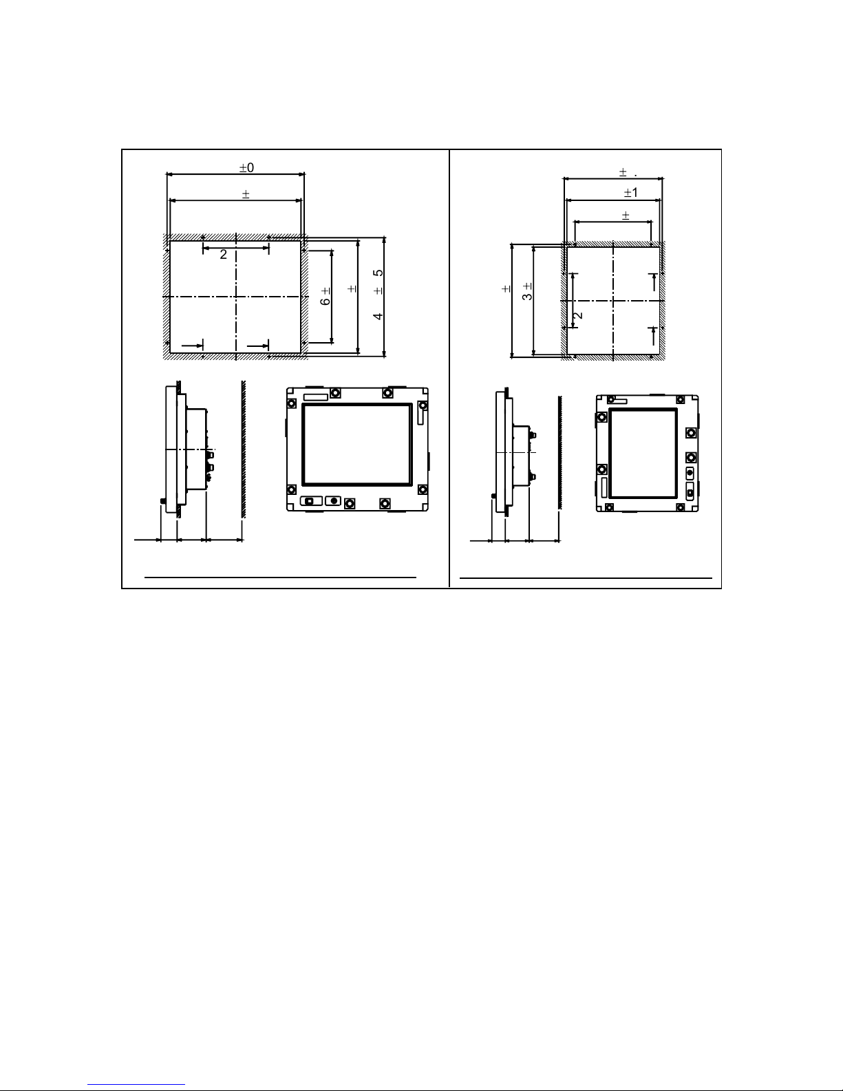
When lifting the display unit, hold it
together with the cover.
Grasping by the cover alone may allow
the display unit to fall, resulting in
possible injury or damage to the equipment.
Ground the equipment to
prevent mutual interference.
MU-200C
Standard Steering
compass compass
2.5 m 1.4 m
Safety Instructions for the Installer

ii
TABLE OF CONTENTS
FOREWORD.........................................................................................................iii
SYSTEM CONFIGURATION................................................................................iv
EQUIPMENT LISTS ..............................................................................................v
1INSTALLATION ................................................................................................1
1.1 Installing the Display Unit ................................................................................................1
2WIRING.............................................................................................................4
2.1 Wiring External Equipment ..............................................................................................4
3ADJUSTMENTS ...............................................................................................7
3.1 Picture Adjustment...........................................................................................................7
3.2 RGB Adjustment..............................................................................................................9
3.3 Brilliance..........................................................................................................................9
4OPERATION...................................................................................................10
5MAINTENANCE, TROUBLESHOOTING.......................................................11
5.1 Maintenance.................................................................................................................. 11
5.2 Troubleshooting.............................................................................................................12
APPENDIX.......................................................................................................AP-1
Parts Location .................................................................................................................AP-1
Parts List .........................................................................................................................AP-2
Interconnection Diagram .................................................................................................AP-3
Modification for Switching from Landscape to Portrait Orientation ...................................AP-4
SPECIFICATIONS...........................................................................................SP-1
PACKING LIST
OUTLINE DRAWING
INTERCONNECTION DIAGRAM
SCHEMATIC DIAGRAMS

iii
FOREWORD
A Word to the Owner of the MU-200C
FURUNO Electric Company thanks you for purchasing the MU-200C 20.1” Multi-Purpose
LCD Display. We are confident you will discover why the FURUNO name has become
synonymous with quality and reliability.
For over 50 years FURUNO Electric Company has enjoyed an enviable reputation for
quality and reliability throughout the world. This dedication to excellence is furthered by our
extensive global network of agents and dealers.
Your equipment is designed and constructed to meet the rigorous demands of the marine
environment. However, no machine can perform its intended function unless properly
installed and maintained. Please carefully read and follow the operation, installation and
maintenance procedures set forth in this manual.
We would appreciate feedback from you, the end-user, about whether we are achieving our
purposes.
Thank you for considering and purchasing FURUNO.
Features
•
Main or remote display for radars, video sounders, sonars and position-fixing equipment.
Compatible equipment: FR-2105B Series, FCV-1200 series, FCV-1500 series, FSV-24,
GD-280/360/380, etc.
•
High resolution display of 1280 X 1024 dot (SXGA), 640 X 480 dot (VGA)
•
Brightness of more than 200 cd/m
2
for comfortable viewing day and night
•
Landscape or portrait orientation
•
Wide viewing angle of 160° for observation by more than one person

i
v
SYSTEM CONFIGURATION
100 - 240 VAC
Navigator (GPS, etc.)*
Control unit of
Vi eo Soun er
(e.g., FCV-1200 series)
Ra ar, Vi eo Plotter,
Navigator, Vi eo Soun er,
Scanning Sonar, etc.
Equipment Category: Protecte
* = When using the FCV-1200 series,
NMEA 0183 ata may be input to the
processor unit of the echo soun er,
via the MU-200C.
NMEA 0183
RGB
Connectable equipment
MU-200C Display Unit Type
Equipment
Landscape Portrait*
FR-2105B Series Yes No
FCV-1200 Series Yes Yes (Modification required)
FCV-1500 Series No Yes (Modification required)
FSV-24 Yes No
GD/GP-280/380/680 Yes No
*=Display should not be viewed with polarized sunglasses.

v
EQUIPMENT LISTS
Standard supply
Name Type Code No. Qty Remarks
Display Unit MU-200C −1
Spare Parts SP10-02803 001-414-950 1set
Installation Materials CP10-05001001-414-550 1set
Accessories FP10-02501001-414-490 1set
See list at end of manual
Optional equipment
Name Type Code No. Qty Remarks
Hood (Landscape) FP10-02612 001-414-770 1
Hood (Portrait) FP10-02613 001-414-790 1

This page is intentionally left blank.

1
1 INSTALLATION
Refer to the outline drawing at the end of the manual for mounting dimensions.
Note: The LCD is made of glass. Handle it with care.
1.1 Installing the Display Unit
The display unit is designed to be flush mounted in a console. When selecting a mounting
location, keep in mind the following points:
• Locate the unit out of direct sunlight.
• Select a location where the display can be easily viewed and the controls can be easily
operated.
• Leave sufficient space around the unit for servicing and maintenance. See the outline
drawing for recommended servicing space.
• The unit weighs 50.7 lbs (23 kg). Be sure the mounting location is strong enough to
support the weight of the unit.
• Locate the unit away from areas subject to water splash and rain.
Procedure
1. Using the paper template supplied in the installation materials, make a cutout in the
mounting location. (Modification of the LCD may be necessary depending on equipment
used. See the table on page iv and “Modification for Switching from Landscape to
Portrait Orientation” in the Appendix for details.)
2. Pull the display unit cover toward you to detach it.
CAUTION
Hold the cover and display unit
together.
The display unit may fall if only the cover
is held.
Cover Display Unit
Display unit and cover

2
3. Fasten the display unit to the mounting location with eight tapping screws (5X30).
Note: Hex head bolts may also be used to fasten the display unit. However, their length
must be at least 30 mm.
45 115 100
501
±
0.5
483
±
1
440
±
0.5
422
±
1
346
±
0.5
226
49 113
45 115 100
501
±
0.5
483
±
1
440
±
0.5
422
±
1
346
±
0.5
226
49 113
Mounting dimensions for landscape orientation Mounting dimensions for portrait orientation
Unit: mm Unit: mm
Mounting dimensions
4. Reattach the cover.
5. For the portrait model only, attach the FURUNO logo seal (supplied) at the top left
corner. (Remove the logo seal at the bottom left corner.)

3
1.1.1 Hood (option)
A hood (portrait or landscape) is optionally available. Attach it to the display unit with Velcro
tape as shown below.
1. Attach nine sets of Velcro tape to the display unit at the locations shown below, in as
straight as possible.
Attach
in line.
Attach
in line.
Display unit, how to attach Velcro tapes
2. Attach the hood to the display unit.

4
2 WIRING
2.1 Wiring External Equipment
Connect external equipment to the MU-200C by referring to the drawings in this section. A
cable with connector at both ends is provided to connect equipment. For details, see the
interconnection diagram on page S-1.
General-purpose monitor
To use the MU-200C as a general-purpose monitor, connect equipment with a mini D-SUB
15P connector. In this case do not connect a navigator to the NMEA port. Nav data is output
through the D-SUB 25P connector.
100 - 240 VAC
Ground
Terminal
Mini D-SUB
15P
FR-2105B Series: PROCESSOR UNIT J2
FSV-24: DISPLAY UNIT MONITOR
FCV-1200 Series: INTERFACE UNIT RGB OUT
FCV-1500 Series: DISPLAY UNIT DISPLAY
GP/GD-280/380/680: DISPLAY UNIT EXT VIDEO
Display unit, rear view, wiring using general-purpose video cables
Note: Use the following cable or the equivalent:
Mini D-SUB 15P: EVNPS05-50 ft, male-female, (max. 15 m)
Manufacturer: BlackBox Japan

5
Connecting FCV-1200 series
Using the cables designated below (or equivalent) to connect the FCV-1200 series makes
the interface unit of the FCV-1200 series unnecessary. The mini D-SUB 15 P connector
cannot be used to connect the FCV-1200 series.
Navigator
FCV-1200 Series:
CONTROL UNIT CONT
FCV-1200 Series:
PROCESSOR UNIT CN1
Cable type
06S4078
Cable type
MJ-A10SPF0002-015
100 - 240 VAC
Ground
Terminal
Display unit, rear view, wiring using specialty cables
Notes on wiring
• The cover of the D-SUB connector of the cable 06S4078 may be removed to pass the
cable through tubing, bulkhead, etc. Use vinyl tape to bind connector wiring and rubber
cover. This allows the cable to be passed through a hole having a diameter of 30 mm.
• Attach connector SRCN6A13-3S (supplied in installation materials) to the power cable
(cable DPYC-1.5 (Japan Industrial Standard) or equivalent).
Sectional view of cable DPYC-1.5
Armor
Conductor
S = 1.5 mm
2
f
= 1.56 mm
Vinyl
sheath
Armor
21
3
Connector Housing
Screw
Clamp Tighten
set screw Connect to
"1" and "2".
Solder Side
Armor
2 cm
Sheath
3mm
Armor
Attaching connector SRCN6A13-3S
1: AC (L: Live line)
2: AC(N: Neutral line)
How to attach connector SRCN6A13-3S; sectional view of power cable DPYC-1.5

6
• Cable 06S4078 is of waterproof construction, however, the MU-200C is not waterproof
(specification IPX0). Therefore, remove rubber cover and fixing metal from the display
side of the cable.
Remove rubber cover.
Remove fixing metal.
D-SUB connector

7
3 ADJUSTMENTS
Controls for adjustment of the picture are provided on the rear of the display unit. Open the
small cover to access the controls.
CONT NMEA
DATA/VIDEO IN
3A POWER 100-240 VAC
50-60 Hz
12
3
GND
S1 S2 S3 S4
J16 J17 J18
R1
R2
R3
J16
J17
J18
R1
R2
R3
EXTBILL
BRILL
BRTP
G
B
B
S1
S2
S3
S4
SEL
UP
DOWN
RESET
131313
Controls for adjustment
of picture (remove cover
to access)
Rear panel
3.1 Picture Adjustment
Contrast and picture are adjusted with
[S1]: Opens OSD (On Screen character Display) menu; selects menu items. See the next
page for description of OSD menu.
[S2]: Increases setting.
[S3]: Decreases setting.
[S4]: Initializes setting.
About the picture adjustment buttons
• [S2]/[S3] may be pressed and held down to increase/decrease setting more rapidly.
• Press buttons within ten seconds of each other. Otherwise, the previous condition is
restored.
• Press the [S4] button more than two seconds to initialize setting.

8
OSD menu
BRIGHTNESS
CONTRAST
RGB
>>
i
COLOR
GAMMA
i
RGB
>>
RGB
>>
A.G.C.
H.POSITION
V.POSITION
i
SIZE
FOCUS
AUTO ADJUST
OSD POSITION
>>
LANGUAGE
>>
i
ALL RESET
RESOLUTION
H.SYNC
V.SYNC
SIGNAL SOURCE
ANALOG
1280x1024
64. 1kHz
60. 1 Hz
i
[S3]
[S2]
[S3]
[S2]
[S3][S2]
[S3]
[S2]
[S1]
These items are
for reference only;
they cannot be
adjusted.
OSD menu
Description of OSD menu
No. Item Description
1 Brightness Not used.
2 Contrast Adjusts LCD contrast.
3 Color Adjusts black level to match input signal level.
4 Gamma Adjusts tone characteristics.
5 A. G. C. (Auto Gain Control) Adjusts auto gain to match amplitude of input signal level.
6 H. Position Adjusts horizontal position.
7 V. Position Adjusts vertical position.
8 Size Adjusts dot clock frequency to match input signal.
9 Focus Adjusts clock delay.
10 Auto Adjust Automatically adjusts position, size and clock.
11 OSD Position Adjusts menu position.
12 Language Chooses menu language from English, German, French
and Spanish.
13 All Reset Restores default settings for items 1-9, 11 and 12.
14 Information Displays input signal information: Input signal resolution,
horizontal synchronization signal and vertical
synchronization signal frequencies.

9
3.2 RGB Adjustment
Color may be adjusted with the following potentiometers on the rear panel. Turn the
potentiometer clockwise to increase color.
Model Potentiometer Setting
FCV-1200 Series Default setting
FSV-24, GD/GP-280/380/680,
FCV-1500 Series, FR-2105B Series Fully clockwise
R1: Red
R2: Green
R3: Blue
3.3 Brilliance
Brilliance of the display unit can be adjusted from the control unit of the FCV-1200 series by
setting jumper block J17 as below.
J17: Brilliance control circuit selection
1-2: Brilliance is adjusted from the MU-200C (default setting)
2-3: Brilliance is adjusted from the control unit of the FCV-1200 series
Note: Do not change the setting of the J16 or J18. The default setting for both is “1-2”.
S1 S2 S3 S4
J16 J17 J18
R1
R2
R3
J16
J17
J18
R1
R2
R3
EXTBILL
BRILL
BRTP
G
B
B
S1
S2
S3
S4
SEL
UP
DOWN
RESET
131313
Jumper blocks

10
4 OPERATION
FURUNO
POWER
Switch
BRILLIANCE ControlLED
Display unit
POWER switch: Turns the power on/off. The LED lamp lights in green when the unit
is turned on and goes off when the unit is turned off.
To turn the MU-200C on and off from the control unit of a video
sounder such as the FCV-1200 series, turn on the POWER switch
of the MU-200C. Note that with the MU-200C turned on and the
FCV-1200 turned off the LED on the MU-200C lights in red. This
means that weak current is flowing to the MU-200C. To turn off the
power completely, turn off the MU-200C.
BRILLIANCE control: Adjusts display brilliance. In some instances brilliance is controlled
from the equipment connected (for example, FCV-1200 series).
LED: Shows display status:
Green: Display on
Red: Power save

11
5 MAINTENANCE,
TROUBLESHOOTING
WARNING
ELECTRICAL SHOCK HAZARD
Do not open the equipment.
Only qualified personnel
should work inside the
equipment.
5.1 Maintenance
Routine maintenance
Regular maintenance is important for good performance. Check the following on a regular
basis to keep the equipment in good operating condition.
• Check that the connectors at the rear of the display unit are tightly fastened.
• Check the ground wire and ground terminal for rust. Clean if necessary. Confirm that the
ground wire is tightly fastened.
• Do not use chemical cleaners to clean any part of the display unit – they can remove
paint and markings.
• Wipe the LCD carefully to prevent scratching, using tissue paper and an LCD cleaner.
To remove dirt or salt deposits, use an LCD cleaner, wiping slowly with tissue paper so
as to dissolve the dirt or salt. Change paper frequently so the salt or dirt will not scratch
the LCD. Do not use solvents such as thinner, acetone or benzene for cleaning.
Fuse replacement
The 3 A 250 V fuse on the rear panel protects the equipment from internal fault and
overvoltage. If the fuse blows, find the cause before replacing it. If the fuse blows again
after replacement, request service.
WARNING
Use the proper fuse.
Use of a wrong fuse can cause fire or
damage to the equipment.

12
5.2 Troubleshooting
The table below provides troubleshooting procedures to use when no picture appears. If
you cannot restore the picture, do not attempt to check inside the equipment – there are no
user serviceable parts inside. Refer any work to a qualified technician.
Troubleshooting table
Reason for no picture Remedy
Ship’s mains voltage is too high. Check voltage.
Fuse has blown. Replace fuse.
Cable between MU-200C and external
equipment has loosened.
Refasten cable.
Power cable has loosened. Refasten cable.
This manual suits for next models
1
Table of contents
Other Furuno Monitor manuals

Furuno
Furuno MFD8 Instruction Manual

Furuno
Furuno NAVNET 3D MFDBB User manual

Furuno
Furuno NAVNET 3D MFDBB User manual

Furuno
Furuno MU-155C Manual

Furuno
Furuno TZTL12F User manual

Furuno
Furuno FEA-2107 User manual

Furuno
Furuno FMD-3200-BB Manual

Furuno
Furuno PM30 User manual

Furuno
Furuno FMD-3300 Manual

Furuno
Furuno MU-150HD User manual

Furuno
Furuno MFD8 Manual

Furuno
Furuno TZTL12F Manual

Furuno
Furuno FMD-3200 User manual

Furuno
Furuno FMD-1712 User manual

Furuno
Furuno MFD8 User manual

Furuno
Furuno MFD8 Instruction Manual

Furuno
Furuno TZT9 Instruction Manual

Furuno
Furuno FMD1920C User manual

Furuno
Furuno RD-30 User manual

Furuno
Furuno MU-190 User manual