Furuno IC-350 User manual

ALARM UNIT
IC-350
OPERATOR'S MANUAL
www.furuno.com
Model


i
IMPORTANT NOTICES
General
• This manual has been authored with simplified grammar, to meet the needs of international users.
• The operator of this equipment must read and follow the descriptions in this manual. Wrong oper-
ation or maintenance can cancel the warranty or cause injury.
• Do not copy any part of this manual without written permission from FURUNO.
• If this manual is lost or worn, contact your dealer about replacement.
• The contents of this manual and equipment specifications can change without notice.
• The example screens (or illustrations) shown in this manual can be different from the screens you
see on your display. The screens you see depend on your system configuration and equipment
settings.
• Save this manual for future reference.
• Any modification of the equipment (including software) by persons not authorized by FURUNO will
cancel the warranty.
• The following concern acts as our importer in Europe, as defined in DECISION No 768/2008/EC.
- Name: FURUNO EUROPE B.V.
- Address: Ridderhaven 19B, 2984 BT Ridderkerk, The Netherlands
• All brand and product names are trademarks, registered trademarks or service marks of their re-
spective holders.
How to discard this product
Discard this product according to local regulations for the disposal of industrial waste. For disposal
in the USA, see the homepage of the Electronics Industries Alliance (http://www.eiae.org/) for the
correct method of disposal.
How to discard a used battery
Some FURUNO products have a battery(ies). To see if your product has a battery, see the chapter
on Maintenance. Follow the instructions below if a battery is used. Tape the + and - terminals of bat-
tery before disposal to prevent fire, heat generation caused by short circuit.
In the European Union
The crossed-out trash can symbol indicates that all types of batter-
ies must not be discarded in standard trash, or at a trash site. Take
the used batteries to a battery collection site according to your na-
tional legislation and the Batteries Directive 2006/66/EU.
In the USA
The Mobius loop symbol (three chasing arrows) indicates that Ni-
Cd and lead-acid rechargeable batteries must be recycled. Take
the used batteries to a battery collection site according to local
laws.
In the other countries
There are no international standards for the battery recycle symbol. The number of symbols can in-
crease when the other countries make their own recycle symbols in the future.
Cd
Ni-Cd Pb
ii
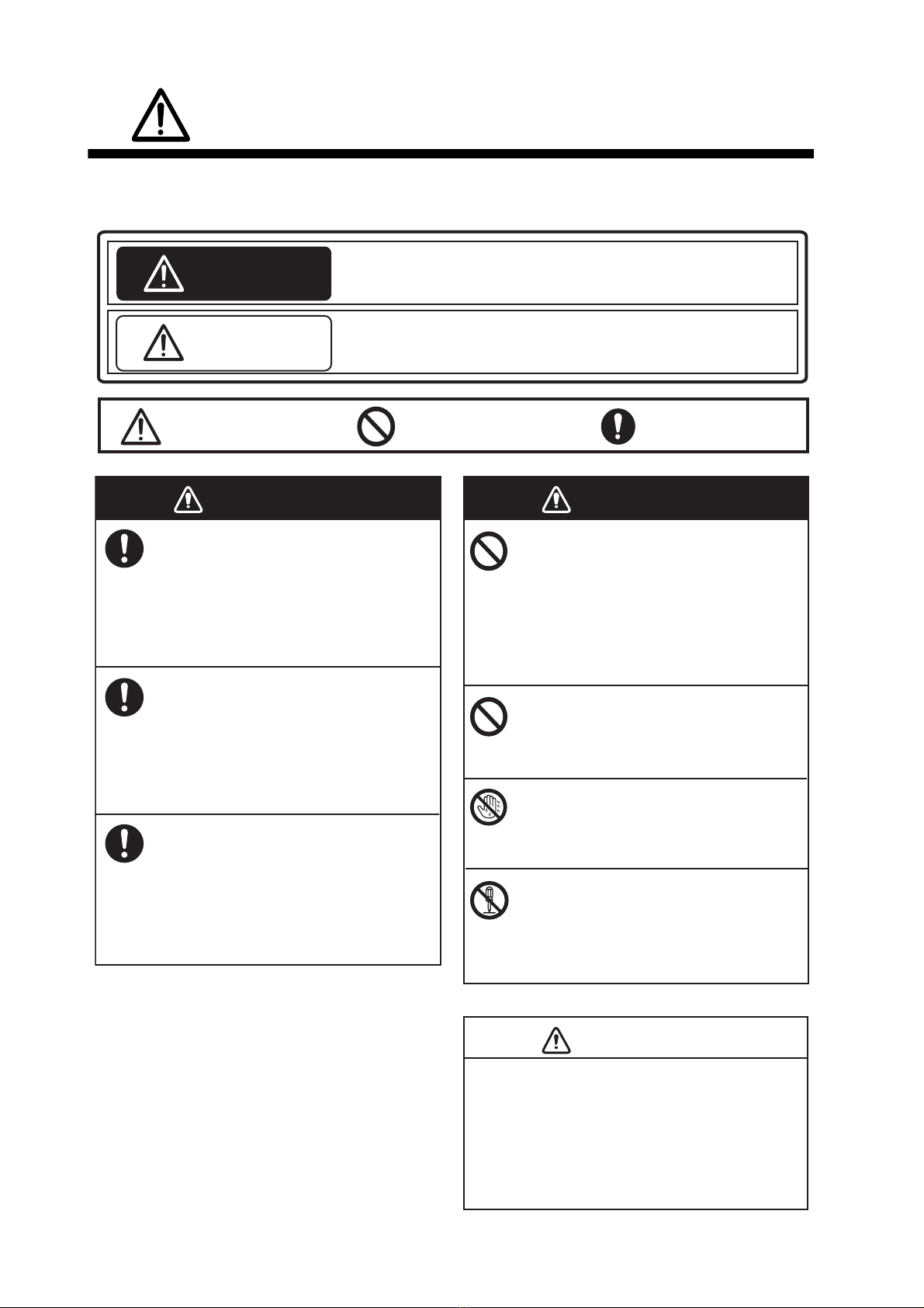
SAFETY INSTRUCTIONS
WARNING
Indicates a potentially hazardous situation which, if not avoided,
could result in death or serious injury.
CAUTION
Indicates a potentially hazardous situation which, if not avoided,
may result in minor or moderate injury.
Warning, Caution Mandatory Action
Prohibitive Action
The installer and operator of this equipment must read these safety instructions before
attempting to install or operate the equipment.
WARNING
If something is dropped into the equip-
ment or water leaks into the equipment,
turn off the power at the switchboard
immediately.
Continued use of the equipment can cause
fire or electrical shock.
If the equipment is emitting smoke or
fire, shut off the power at the switch-
board immediately.
Continued use of the equipment can cause
fire or electrical shock. Consult a FURUNO
agent or dealer for advice.
If the equipment is acting abnormally,
shut off the power at the switchboard
immediately.
Continued use of the equipment can cause
fire or electrical shock. Consult a FURUNO
agent or dealer for advice.
WARNING
Do not operate a DISTRESS button
unless YOUR vessel is in distress.
The distress signal is sent when a
DISTRESS button is operated. If the
distress signal is accidentally sent, contact
a coast station immediately to report
accidental distress transmission.
Do not place liquid-filled containers on
the top of the equipment.
Fire or electrical shock can result.
Do not operate the equipment with wet
hands.
Electrical shock can result.
Do not disassemble or modify the
equipment.
Electrical shock, fire or bodily injury can
result.
CAUTION
If distress is accidentally sent, immediately
contact a coast station and provide the
following information:
- Ship's name
- Ship's call sign and DSC number
- Position at time of distress transmission
- Time of distress transmission
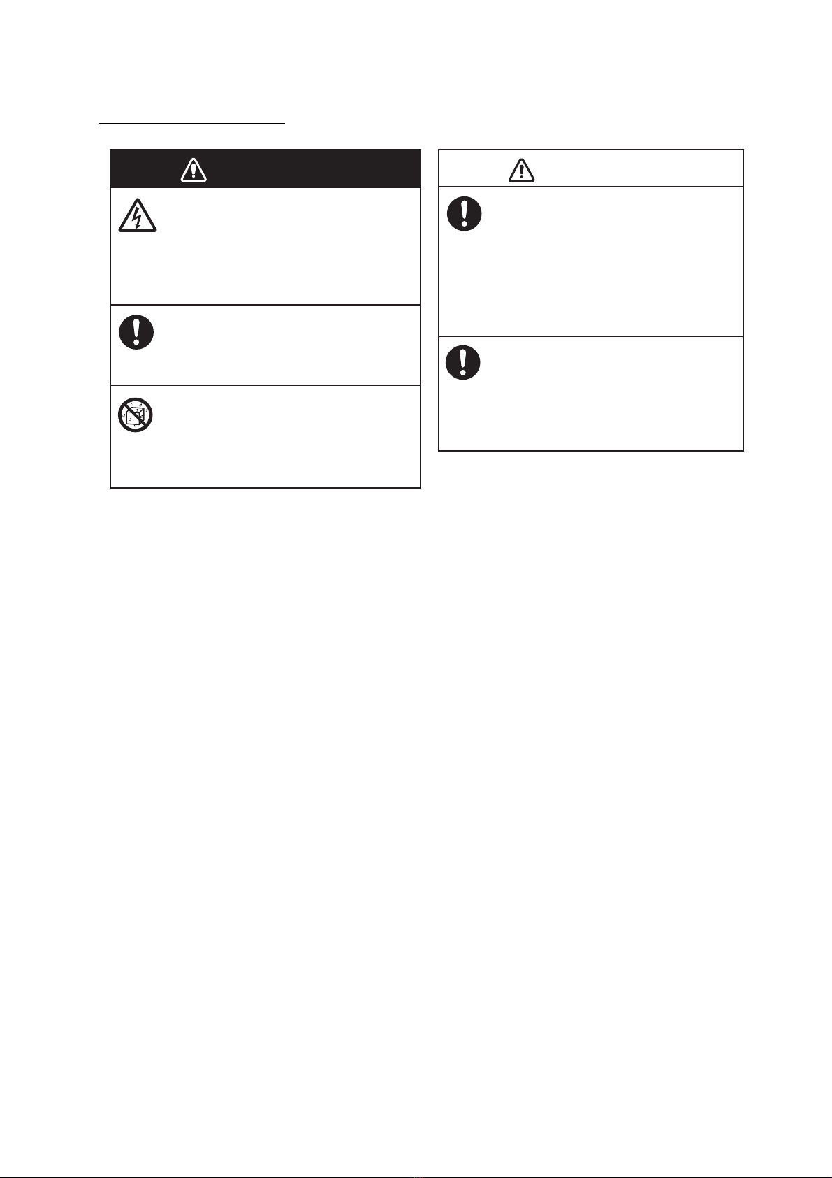
SAFETY INSTRUCTIONS
iii
Precautions for the installer
Be sure the voltage at the ship's switch-
board is compatible with the voltage
rating of this equipment.
The rated voltage of this equipment is
24 VDC. Damage to the equipment can
result if the equipment is connected to an
incompatible power supply.
Observe the compass safe distances
shown below to prevent interference to
a magnetic compass.
Standard compass: 1.20 m
Steering compass: 0.75 m
CAUTION
WARNING
Shut off the power at the switchboard
before beginning the installation.
Fire or electrical shock can result if the
equipment is powered while it is being
installed.
Use only the specified power cable.
Fire or electrical shock can result if a
different cable is used.
Do not install the equipment where it
can get wet from rain or water splash.
Fire or electrical shock can result if water
gets inside the equipment.

iv
TABLE OF CONTENTS
FOREWORD .................................................................................................................. v
SYSTEM CONFIGURATION ........................................................................................ vi
1. INSTALLATION ...................................................................................................... 1
1.1 Equipment Lists........................................................................................................... 1
1.2 How to Install the Alarm Unit....................................................................................... 1
1.3 Connections ................................................................................................................ 2
1.3.1 Where to connect the cables ............................................................................... 2
1.3.2 Cable fabrications ................................................................................................ 3
1.4 Settings ....................................................................................................................... 6
2. OPERATION ........................................................................................................... 9
2.1 Controls and Indicators ............................................................................................... 9
2.2 How to Set the Unit to Stand-by.................................................................................. 9
2.3 When You Receive a Distress Signal ....................................................................... 10
2.4 How to Send a Distress Signal.................................................................................. 10
2.5 How to Operate the Dual Alarm Unit......................................................................... 11
3. MAINTENANCE .................................................................................................... 12
3.1 Maintenance.............................................................................................................. 12
3.2 How to Clean the Equipment .................................................................................... 12
3.3 Circuit Breaker .......................................................................................................... 13
3.4 Troubleshooting ........................................................................................................ 13
3.5 Equipment Test ......................................................................................................... 13
SPECIFICATIONS ................................................................................................... SP-1
OUTLINE DRAWING ................................................................................................. D-1
INTERCONNECTION DIAGRAM .............................................................................. S-1

v
FOREWORD
Congratulations on your choice of the FURUNO IC-350 Alarm Unit. We are confident you will see
why the FURUNO name has become synonymous with quality and reliability.
Since 1948, FURUNO Electric Company has enjoyed an enviable reputation for quality marine
electronics equipment. This dedication to excellence is furthered by our extensive global network
of agents and dealers.
This equipment is designed and constructed to meet the rigorous demands of the marine environ-
ment. However, no machine can perform its intended function unless installed, operated and
maintained properly. Please carefully read and follow the recommended procedures for installa-
tion, operation and maintenance.
Features
The IC-350 globally controls the distress functions of all GMDSS equipment connected to it. The
main features are
• Connects to six GMDSS units: one SSB radiotelephone, two VHF radiotelephones, two Inmar-
sat-C mobile earth stations (MES), and one NAVTEX receiver.
• Dedicated DISTRESS buttons for sending a distress alert.
• MUTE ALARM button stops audio alarm.
• Second alarm unit (option) allows control from a remote location.
CE declaration
With regards to CE declarations, please refer to our website (www.furuno.com) for further infor-
mation about RoHS conformity declarations.

vi
SYSTEM CONFIGURATION
Standard configuration shown with solid lines.
ALARM UNIT
IC-350
(No.1)
External
Alarm
SSB
Radiotelephone
No.1 VHF
Radiotelephone
No. 2 VHF
Radiotelephone
No. 1
Inmarsat-C MES
No. 2
Inmarsat-C MES
NAVTEX
Receiver
Alarm Unit
IC-350
(No.2)
Rectifier
PR-62
24 VDC
100/110/
220/230 VAC
1φ, 50/60 Hz
AC-DC Power
Supply Unit
PR-240
24 VDC
Category Program number
Protected from
the weather 0550235-01
Incoming
Indicator
IC-303
100 - 115/
200 - 230 VAC
1φ, 50/60 Hz
Can be connected only
when SSB radiotelephone
FS-1570/2570/5070 is
connected.
(Backed-up battery)
(Power source which is
backed-up by radio battery)
1
1. INSTALLATION
1.1 Equipment Lists
Standard supply
Optional supply
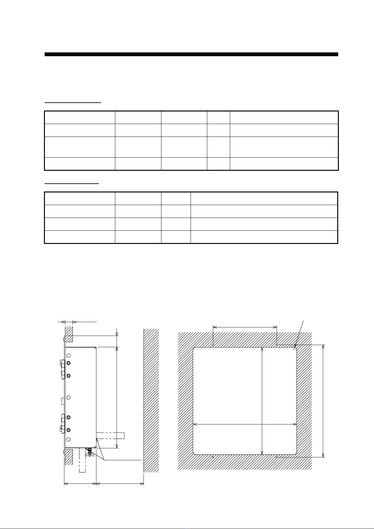
1.2 How to Install the Alarm Unit
See the outline drawing at the back of this manual for dimensions. Install the alarm unit in a con-
sole. Make a cutout in the location for the unit, the dimensions of which are 277(W)×287(H). Set
the unit to the cutout. Fasten the unit with four self-tapping screws (supplied).
Name Type Code No. Qty Remarks
Alarm Unit IC-350 — 1
Installation Materials CP05-11701 000-041-190 1 set Self-tapping screws (φ4×20, 4pcs)
(000-158-850-10)
Accessory FP05-06401 001-058-090 1 SPARE sticker
Name Type Qty Remarks
Rectifier PR-62 1 AC input, 24 VDC output
AC-DC Power Supply PR-240 1 AC, DC input, 24 VDC output
Alarm Unit IC-350 1 for dual connection
R8
#100
300 ±0.5
170 ±0.5
10-20
270 30
277 ±2
287 ±2
85
CABLE ENTRY
CUTOUT DIMENSIONS (REFERENCE)
1. INSTALLATION
2
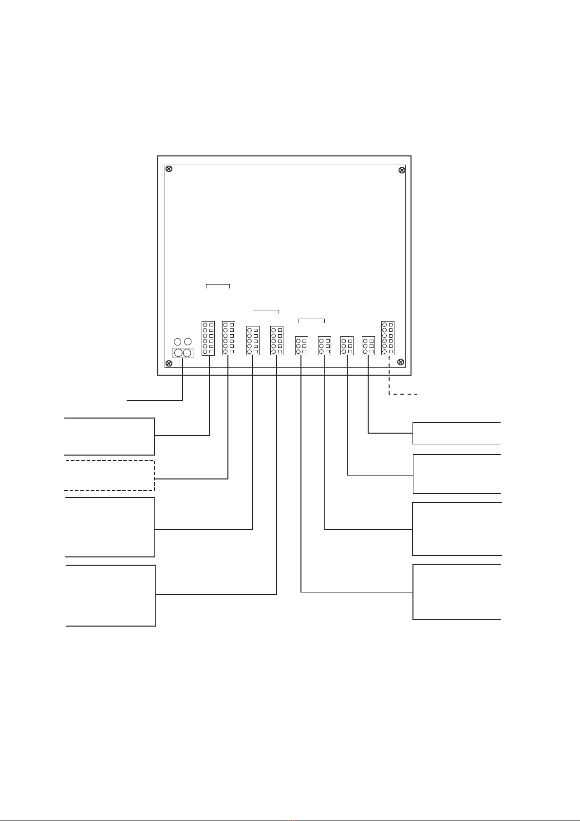
1.3 Connections
1.3.1 Where to connect the cables
The cable connections for external equipments are as shown in the following figure. Refer to the
interconnection diagram at the back of this manual for details.
External Alarm
NAVTEX Receiver
Inmarsat C MES
FELCOM 18
Junction Box
IC-318
NX-700 Receiver NX-7001
J403
TB #3 - 4
TTYCS(LA)-1
DPYC-1.5
TTYCS(LA)-1
TTYCS(LA)-1
POWER *1
24 VDC
DPYC-1.5
SSB Radiotelephone
FS-1575/2575/5075
Transceiver TB7
A
lerm unit *2
IC-350 (No.2) J3
TTYCS(LA)-4
TTYCS-4(LA)
VHF Radiotelephone
FM-8900S
Junction box
IF-8900
VHF Radiotelephone
FM-8900S
Junction box
IF-8900
TB8
TB8
TTYCS(LA)-4
TTYCS(LA)-4
24VDC
DST
BZ
RCV
BZ/
IC-350
DUAL No.1 No.2
No.1 No.2
NAVTEX
EXT
ALARM
No.2
EXT
ALARM
No.1
MF/HF
VHF
INMARSAT-C
+
-
Inmarsat C MES
FELCOM 18
Junction Box
IC-318
TB #3 - 4
*2
IC-303 *3
*1: Power must be supplied from a power source which is backed-up by radio battery.
*2: IC-350 dual installation requires setting modification.
*3: The IC-303 can be connected only when the SSB radiotelephone FS-1570/2570/5070 is connected.
The dashed line indicates optional equipment.
Table of contents
Other Furuno Security System manuals

Furuno
Furuno BR-500 User manual

Furuno
Furuno FB-3101 User manual

Furuno
Furuno BR-500 User manual

Furuno
Furuno BR-1000 User manual

Furuno
Furuno BR-500 User manual

Furuno
Furuno felcom15 User manual

Furuno
Furuno FELCOM16 User manual

Furuno
Furuno IC-307 User manual

Furuno
Furuno SSAS User manual

Furuno
Furuno BR-1000 User manual
Popular Security System manuals by other brands


EDM
EDM Solution 6+6 Wireless-AE installation manual

Highway Safety Group
Highway Safety Group EA401 user manual

Siren
Siren LED GSM operating manual

Detection Systems
Detection Systems 7090i Installation and programming manual

Se-Kure Controls
Se-Kure Controls MicroMini SK-4841 instructions

Siemens
Siemens FDM273 manual