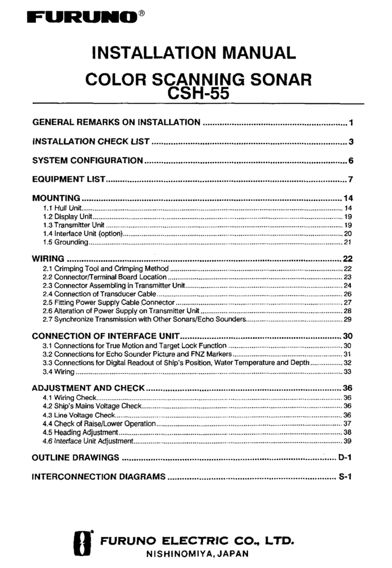
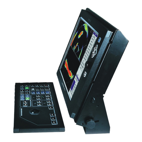
Furuno CH-37 User manual

www.furuno.com
A
ll brand and product names are trademarks, registered trademarks or service marks of their respective holders.
Installation Manual
COLOR SECTOR SCANNING SONAR
CH-37
SAFETY INSTRUCTIONS ................................................................................................ i
SYSTEM CONFIGURATION .......................................................................................... iii
EQUIPMENT LISTS......................................................................................................... v
1. MOUNTING..............................................................................................................1-1
1.1 Hull Unit .............................................................................................................................1-1
1.2 Transceiver Unit...............................................................................................................1-13
1.3 Display Unit......................................................................................................................1-14
1.4 Grounding the Display Unit and Transceiver Unit............................................................1-14
1.5 Motion Sensor MS-100 (Option) ......................................................................................1-15
1.6 External Interface (Option)...............................................................................................1-15
1.7 Logarithm Amplifier Video Sounder .................................................................................1-16
1.8 Clinometer BS-704 (Option).............................................................................................1-17
2. WIRING....................................................................................................................2-1
2.1 Wiring Among Units ...........................................................................................................2-1
2.2 Synchronizing Transmission with Echo Sounder or Other Sonar ......................................2-4
3. ADJUSTMENTS ......................................................................................................3-1
3.1 General Checks .................................................................................................................3-1
3.2 Adjustment of Transceiver Unit..........................................................................................3-2
3.3 Heading Alignment.............................................................................................................3-3
3.4 Adjustment of Motion Sensor, Clinometer .........................................................................3-4
3.5 Soundome Painting............................................................................................................3-5
3.6 LED Status.........................................................................................................................3-5
4. CHANGING SPECIFICATIONS ..............................................................................4-1
4.1 System Menu .....................................................................................................................4-1
PACKING LISTS ......................................................................................................... A-1
OUTLINE DRAWINGS ................................................................................................ D-1
INTERCONNECTION DIAGRAM ................................................................................ S-1

7KHSDSHUXVHGLQWKLVPDQXDO
LVHOHPHQWDOFKORULQHIUHH
࣭)85812$XWKRUL]HG'LVWULEXWRU'HDOHU
$VKLKDUDFKR
1LVKLQRPL\D-$3$1
$ -8/
3ULQWHGLQ-DSDQ
$OOULJKWVUHVHUYHG
- 2&7
3XE1R ,0(-
(70, &+

i
SAFETY INSTRUCTIONS
WARNING
Indicates a condition that can cause death or serious
injury if not avoided.
CAUTION
Indicates a condition that can cause minor or moderate
injury if not avoided.
Warning, Caution Mandatory Action
Prohibitive Action
Read these safety instructions before you operate the equipment.
WARNING
ELECTRICAL SHOCK HAZARD
Do not open the equipment
unless totally familiar with
electrical circuits and
service manual.
Only qualified personnel
should work inside the
equipment.
WARNING
Install the specified transducer tank
in accordance with the installation
instructions. If a different tank is to be
installed the shipyard is solely respon-
sible for its installation, and it should
be installed so the hull will not be
damaged if the tank strikes an object.
The tank or hull may be damaged if the
tank strikes an object.
If a steel tank is installed on a wooden
or FRP vessel, take appropriate
measures to prevent electrolytic
corrosion.
Electrolytic corrosion can damage the
hull.
Be sure that the power supply is
compatible with the voltage rating of
the equipment.
Connection of an incorrect power supply
can cause fire or equipment damage. The
voltage rating of the equipment appears
on the label above the power connector.
Turn off the power at the switchboard
before beginning the installation.
Fire or electrical shock can result if the
power is left on.
Do not install the equipment where it
may get wet from rain or water splash.
Water in the equipment can result in fire,
electrical shock or equipment damage.
Be sure no water leaks in at the trans-
ducer installation site.
Water leakage can sink the vessel. Also
confirm that the transducer will not loosen
by ship's vibration. The installer of the
equipment is solely responsible for the
proper installation of the equipment.
FURUNO will assume no responsibility for
any damage associated with improper
installation.

SAFETY INSTRUCTIONS
ii
CAUTION
Observe the following compass safe
distances to prevent deviation of a
magnetic compass:
Ground the equipment to
prevent electrical shock and
mutual interference.
Display
unit
Standard
compass
2.2 m 1.6 m
WORKING WITH THE SONAR OIL
Precautions
•
Keep oil away from eyes. Wear protective
gloves when working with the oil. The oil
can cause inflammation of the eyes.
•
Do not touch the oil. Wear protective
gloves when working with the oil. The oil
can cause inflammation of the skin.
•
Do not ingest the oil. Diarrhea or vomiting
can result.
•
Keep the oil out of reach of children.
Emergency
•
If the oil enters eyes, flush with clean
water about 15 min. Consult a physician.
•
If the oil contacts skin, wash with soap
and water.
•
If the oil is ingested, see a physician
immediately.
Disposal of oil and its container
Dispose of oil and its container in accord-
ance with local regulations. For further
details, contact place of purchase.
Storage
Seal container to keep out foreign
material. Store in dark place.
Steering
compass

iii
SYSTEM CONFIGURATION
DISPLAY UNIT
CH-370
NOTE 1: Two sets of rectifiers are necessary for AC mains.
NOTE 2: DC ship's mains only. For AC ship's mains, the power
is supplied directly from the rectifier unit to the trans-
ceiver unit.
OPTIONAL SUPPLY STANDARD SUPPLY
LOUDSPEAKER
CA-151S-ASSY / CA-150BS-ASSY
REMOTE CONTROL BOX
CH-343
External
Interface
OP06-13
(Built-in)
External
Interface
OP06-14
(Built-in)
EXTERNAL
MONITOR
: Connector to fitted at installation
: Connector fitted at factory
: Crimp-on lug to be fitted at installation
MOTION
SENSOR
MS-100
or Clinormeter
BS-704
250V-DPYCYS-2
250V-DPYCYS-2
24-32V DC
06S4067 15/30/50M
250V-DPYCYS-2
250V-DPYCYS-2
250V-
DPYCYS-2
02S8040 6M

SYSTEM CONFIGURATION
iv
Hull unit assembly combination
Power Freq. Type Code No.
113kHz
113kHz
Standard Option
Power Freq. Type Code No.
Type Code No. Type Code No. Type Code No.
Mat. Type Code No.
Steel
Alum.
Mat. Type Code No.
Steel Steel
Mat. Type Code No.
5.3m cable3.7 m cable
2.7 m cable
113
113 113
R
/
L
D
R
I
V
E
U
N
I
T
S
H
A
F
T
S
O
U
N
D
O
M
E
T
A
N
K

v
EQUIPMENT LISTS
Standard Supply
Optional Supply
Name Type Code No. Qty Remarks
Display Unit CH-370 - 1
Transceiver Unit CH-341 - 1 60/81/113/162 kHz, select one
Hull Unit CH-342 - 1 60/81/113/162 kHz, 24/32 VDC,
Shaft length 1.17/2.2/3.8 m
Installation
Materials
CP06-01100 000-068-457 Select
one
Cable length: 15 m (standard supply)
CP06-01110 000-068-458 Cable length: 30m
CP06-01120 000-068-459 Cable length: 50m
CP06-01102 006-563-250 1 set For display unit
CP06-01103 006-563-300 1 set For transceiver unit
CP06-01104 006-563-340 1 set For hull unit
Spare Parts SP06-01001 006-563-170 1 set For display unit
SP06-01002 006-563-260 1 set For transceiver unit
SP06-01003 006-563-320 1 set For hull unit
Accessories FP06-01000 000-068-460 1 set Hood, vinyl cover
Name Type Code No. Remarks
Motion Sensor MS-100 -
Clinometer BS-704 -
Remote Control Box CH-343 -
Steel Retraction Tank 06-007-1570 000-065-066 1.0 m
SHJ-0001 000-066-643 1.8 m
06-007-1571 000-065-070 3.5 m
FRP Retraction Tank SHJ-0022 000-066-644 1 m
06-007-1573 000-065-067 1.8 m
Aluminum Retraction
Tank
OP10-5 000-069-763 1 m, with inst. materials
Rectifier RU-1746B-2 000-030-439 110/220 VAC, 2 sets required
E/S Interface VI-1100A 000-021-805
Handle OP03-70 008-423-420
Loudspeaker CA-151S-ASSY 001-466-200 8:
CA-150BS-ASSY 000-190-183
Cable assembly MJ-A6SPF0012-050C 000-154-053 64S4071-2, 5 m, 6 pin-6 pin
MJ-A6SPF0012-100C 000-154-037 64S4071-2, 10 m, 6 pin-6 pin
MJ-A6SPF0011-050C 000-159-690 03S9202-2, 5 m, 6 pin-4 pin
MJ-A6SPF0011-100C 000-159-691 03S9202-2, 10 m, 6 pin-4 pin
5-pair Twisted Cable CO-SPEVV-SB-C
0.2 x 5P
000-560-451 5 m
000-560-452 1 0m
000-560-417 15 m
000-103-868 20 m
48-core Cable 06S4056 000-126-160 For extension of cable be-
tween hull unit and transceiver
unit, specify length

EQUIPMENT LISTS
vi
Filter FP02-02620 002-007-290
External E/S Interface OP06-13 000-068-455
External Monitor
Interface
OP06-14 000-068-456
Fairing 06-021-4502 001-159-790-10 For an FRP ship
Soundome shaft 06-007-1591 001-261-030 3 m
Name Type Code No. Remarks

1-1
1. MOUNTING
1.1 Hull Unit
General mounting considerations
• Noise and air bubbles will affect performance.
• Keep the transducer away from oil. Oil can corrode the cable.
• Do not expose the transducer to hot water. Hot water can damage the transducer.
• Do not turn on the equipment with the transducer exposed to air. Exposing the
transducer to air may damage it.
Installation position considerations
Discussion and agreement are required with the dockyard and ship owner in deciding
the location for the hull unit. When deciding the location, take into account the follow-
ing points:
• Select an area where propeller noise, cruising noise, bubbles and interference from
turbulence are minimal. Generally, the point at 1/3 to 1/2 of the ship’s length from
the bow or near the keel is the best. On-the-keel installation is advantageous for
minimizing oil consumption in comparison with off-the-keel. If the hull unit cannot be
installed on the keel, the center of the retraction tank should be within 1 meter of the
keel to prevent a rolling effect.
• Select a place where interference from the transducers of other sounding equip-
ment is minimal. The hull unit should be at least 2.5 meters away from the transduc-
ers of other sounding equipment.
• An obstacle in the fore direction not only causes a shadow zone but also aerated
water, resulting in poor sonar performance. Be sure to locate the transducer well
away from any obstacle in the fore direction.
NOTICE
Do not apply paint, anti-corrosive
sealant or contact spray to coating or
plastic parts of the equipment.
Those items contain organic solvents that
can damage coating and plastic parts,
especially plastic connectors.
1/2 1/3 Within 1 m

1. MOUNTING
1-2
Mounting method
A typical mounting method is shown in the outline drawing at the back of this manual.
Consult ship’s owner, dockyard and user to determine appropriate mounting method.
Pay attention to safety (strength, watertighness) first, followed by ease of mainte-
nance and inspection.
Tank length
Shorten the transducer tank so the transducer is
lowered into water as deep as possible.
Pay particular attention to the tank length Lt.
Determine the length of the main shaft as described
in the paragraph "Assembling and mounting of hull
unit" on page 1-3.
Note 1: Do not shorten the 1 meter retraction tank.
Shortening it may also necessitate shortening of
the top part of the main shaft, thereby destroying
the watertight construction of the 1.17 meter shaft.
Note 2: When the retraction tank is constructed lo-
cally, finish it so that welding beads do not protrude
on the inner surface of the tank. The tank guide will
hit the bead, burning out the raise/lower motor. Al-
so, do not position the welding bead in the ship’s
fore-aft line.
Note 3: Use of other manufacturer’s tank is permit-
ted. However, the dimensions should be the same
as those in the transducer tank outline drawing.
Mounting of transducer tank
Install the transducer tank referring to the hull unit out-
line drawings at the back of this manual.
Note: Locate one of the bolt holes 10° to port to mini-
mize mechanical shock at the raise/lower block during
pitching and rolling.
Cable gland
Washer
Gasket
Main shaft
(1.17 m䋩
Welding bead
Wealding bead
10°

1. MOUNTING
1-3
Assembling and mounting of hull unit
The hull unit is shipped disassembled as the parts shown in the hull unit kit on pages
1-10 and 1-11. Assemble the hull unit as shown in the procedure below.
Necessary tools
1. Unscrew eight pieces of socket head cap screws with the ball wrench (supplied)
to detach the soundome.
2. Fill the soundome with sonar oil 6 cm below the top of the dome. (Use only the
specified sonar oil. Use of other sonar oils may affect performance.) Reattach the
soundome.
Name Specification Remarks
Wrench For M10 (Hex. size 17 mm)
Wrench For M20 (Hex. size 20 mm)
Pipe Wrench 55 mm
Ball Wrench Hex size 4 mm Supplied with hull unit kit
Rotate 3 or 4 turns by
hand to make sure that
turning mechanisms are
functioning properly.
Socket head cap screw
(8 pcs. M5x30)
Spring washer
NOTE
O-ring
Remove
Apply Kinoruster*.
Soundome
Screw
6 pcs.䇭M5x10
Do not fasten the M5x10 screws.
Oil may leak into the soundome.
Protective sponge
Do not unfasten two nuts
painted in red.
Unfastening the nuts may
allow water to leak inside,
which can damage the
soundome.
Kinoruster*: Anti-crevice
corrosion sealant
(supplied)
NOTE
Sonar oil
5 cm
Frequency (kHz)
60 81 113 162
Sonar oil 4L
䠄000-824-033䠅
Super sonar oil 4L
䠄000-177-561-10䠅
No Yes Yes Yes
Yes No No No
Use packing
material to support
soundome.
Ball㻌wrench

1. MOUNTING
1-4
3. Shorten the main shaft by the length of Lt + 110 mm, where Lt is the length of the
retraction tank. When the retraction tank length is 1 meter do not shorten
the 1.17 meter main shaft.
4. Fasten the main shaft to the soundome assembly as follows;
a) Screw the lock nut onto the main shaft.
b) Pass the transducer cable through the main shaft.
c) After fully screwing the main shaft into the soundome neck, unscrew it by four
turns and apply the supplied sealant (LOCTITE NO.575) to the threads.
d) Screw in the main shaft completely, then tighten the lock nut with a wrench.
e) Remove any excess sealant with a waste cloth. The sealant does not harden
when exposed to air.
f) Tighten the socket-set screw on the lock nut.
CAUTION
WORKING WITH THE SONAR OIL
Precautions
· Keep oil away from eyes. Wear
protectivegloves when working with
the oil. The oilcan cause
inflammation of the eyes.
· Do not touch the oil. Wear protective
gloves when working with the oil.
The oilcan cause inflammation of the
skin.
· Do not ingest the oil. Diarrhea or
vomiting can result.
· Keep the oil out of reach of children.
Emergency
· If the oil enters eyes, flush with clean water
about 15 minutes. Consult a physician.
· If the oil contacts skin, wash with soap and
water.
· If the oil is ingested, see a physician
immediately.
Disposal of oil and its container
· Dispose of oil and its container in
accordance with local regulations. For
further details, contact place of purchase.
Storage
· Seal container to keep out foreign material.
Store in dark place.
Lt 䋫110mm
Supplied Length: 1.17 m (2.2 m, 3.8 m)
Take care not
to scratch.
Chamfer edge to protect
O-ring from damage.

1. MOUNTING
1-5
g) Fasten two reinforce metal fittings to connect the main shaft and the soun-
dome assembly securely (not using the stopper washer).
Figure 1-6 How to fasten main shaft to soundome assembly
5. Clean the main shaft and pass it through the main body flange.
Figure 1-7 Passing main shaft through the main body flange
While holding the soundome neck with a pipe
wrench, tighten the lock nut with another wrench.
Lock nut
Apply the sealant
(LOCTITE NO.575).
Socket-set
screw
Reinforcement
metal fittings
Reinforcement metal
fittings
Hex. bolts (M10x100)
Plain washer/Spring
washer/Nut (4 pcs)
Confirm the O-ring
is in position
Main body flange

1. MOUNTING
1-6
6. Set the grease cotton to the main body flange and tighten the grease cotton re-
tainer temporarily.
Figure 1-8 Installing grease cotton on the main shaft
7. Temporarily fasten the fastening band onto the main shaft at the location shown
below.
Figure 1-9 Fastening the fastening band on the main shaft
8. Inscribe bow mark at the top of the main shaft. Pass pipe clamp through the main
shaft and install washer, gasket and cable gland.
Figure 1-10 Passing pipe clamp, gasket, flat washer and cable gland on main shaft
Wind grease cotton onto
main shaft and cut it as
shown below.
Space joint of grease cotton
120° apart and push them into
body flange.
Flat washer
Lt: Tank length Lt - 430 mm
Fastening band
Pipe clamp
Inscribe bow mark,
referring to the bow mark
on the soundome.
Gasket
Cable gland
Flat washer
Pipe cap
For 2.2/3.8 m shaft
70
3
Tighten cable gland for gap
of approx. 3 mm.
Hold here with
pipe wrench

1. MOUNTING
1-7
9. Fasten the hull unit to the transducer tank, orienting it so the ship’s fore-aft line
crosses the front panel of the raise/lower drive block at an angle of approximately
45 degrees.
Figure 1-11 Fastening the hull unit to the transducer tank
10. Install the raise/lower drive block as follows;
a) Rotate the main shaft so the bow mark faces ship's bow.
b) Install the raise/lower drive block onto the main body flange.
c) Fix the main shaft with the shaft retainer.
d) Loosen the fastening band, slide it up to the shaft retainer and fasten it.
e) Check that the distance from the top of the main shaft to the top of the shaft
retainer is as follows:
• 1.17 m main shaft: 75 mm
• Main shaft cut at Lt + 110 mm: 15 mm
Apply Kinoruster.
M20 x 90 (8 pcs)
M20 Flat washer
M20
Flat washer/
Spring washer/
Nut
Outer edges of main
body flange and tank
should be in line with
one another.
Wipe off foreign material.
45°
Bow
CAUTION:
1. Do not drag hull unit on floor.
2. Do not rest hull unit against wall.
Orient the hull unit as above to
minimize shock and vibration on
the raise/lower drive block when
ship is pitching and rolling.

1. MOUNTING
1-8
If not as shown above, loosen shaft retainer and fastening band to adjust the dis-
tance. This will place the bottom of the soundome 10 mm above the bottom of the
retraction tank when the soundome is retracted.
Figure 1-12 Installing the raise/lower drive block
11. Tighten the grease cotton retainer for a gap of 7 to 9 mm.
Figure 1-13 Tightening the grease cotton retainer
Checking manual raise/lower of transducer with handcrank
Perform this check after all wiring has been completed. Ship’s mains power must ap-
plied to the hull unit, otherwise the magnetic brake of the raise/lower motor activates,
disabling the manual raise/lower gears.
1. Turn off the breaker on the hull unit.
2. Detach the brake-off switch cover.
Raise/lower
drive block
Shaft retainer
Bow
mark
Shaft
Trunnion bolt
10 mm
Fastening band
Fasten for a gap of
1 mm approx.
1.17 m shaft: 75 mm
Shortened shaft: 15 mm
7 to 9 mm
Grease cotton retainer
Grease cotton

1. MOUNTING
1-9
3. Set hand crank to the screw shaft gear and turn it while pressing the brake-off
switch.
4. The transducer should rise/lower smoothly with even force in upper to lower limits.
If not, the centers of the main body flange and the retraction tank are not aligned.
Adjust the hull mounting position if necessary.
Figure 1-14 How to use the hand crank
Breaker
Raise
Lower
Brake Off
switch
Raising/lower manually
without connecting ship’s
mains may damage motor.

1. MOUNTING
1-10
Hull unit installation materials

1. MOUNTING
1-11
䝅䞊䝹
SEALANT
000-194-894-10
LOCTITE NO.575

1. MOUNTING
1-12
Other manuals for CH-37
2
Table of contents
Other Furuno Sonar manuals

Furuno
Furuno CI-68 User manual

Furuno
Furuno FSV-85 User manual

Furuno
Furuno FE-700 User manual

Furuno
Furuno FSV-75 User manual

Furuno
Furuno CI-68 User manual

Furuno
Furuno CSH5LMK2 User manual

Furuno
Furuno TS-331A User manual

Furuno
Furuno CSH-7 User manual

Furuno
Furuno FSV-75 User manual

Furuno
Furuno FSV-24 User manual

Furuno
Furuno CH-270 User manual

Furuno
Furuno CSH-5 User manual

Furuno
Furuno FSV-35S User manual

Furuno
Furuno CI-68 User manual

Furuno
Furuno FE-880 User manual

Furuno
Furuno FSV-84 User manual

Furuno
Furuno CH-500 User manual

Furuno
Furuno FCV-582 User manual

Furuno
Furuno FSV-30 User manual

Furuno
Furuno CH-28 User manual