manuals.online logo
Brands
  1. Home
  2. •
  3. Brands
  4. •
  5. GAGEMAKER
  6. •
  7. Measuring Instrument
  8. •
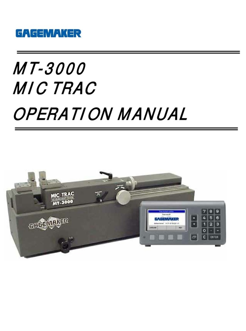
  9. GAGEMAKER MIC TRAC MT-3000 User manual

GAGEMAKER MIC TRAC MT-3000 User manual

M
MI
IC
C
T
TR
RA
AC
C
M
MT
T-
-3
30
00
00
0
T
TF
F-
-V
VB
B
B
Bo
or
re
e
G
Ga
ag
ge
e
F
Fi
ix
xt
tu
ur
re
e
C
CA
AL
L-
-P
PA
AK
K
F
FI
IX
XT
TU
UR
RE
E
M
MA
AN
NU
UA
AL
L
G
Ga
ag
ge
em
ma
ak
ke
er
r
P
Pi
iv
vo
ot
t
A
Ar
rm
m
G
Ga
ag
ge
e
C
CA
AL
L-
-P
PA
AK
K
F
Fi
ix
xt
tu
ur
re
e
M
Ma
an
nu
ua
al
l
MIC TRAC MT-3000
2 2014 Gagemaker, Inc.
RCGPAMT30007-00
©2014 Gagemaker LP
RCGPAMT30007-00
OMTFVB09-10
G
Ga
ag
ge
em
ma
ak
ke
er
r
P
Pi
iv
vo
ot
t
A
Ar
rm
m
G
Ga
ag
ge
e
C
CA
AL
L-
-P
PA
AK
K
F
Fi
ix
xt
tu
ur
re
e
M
Ma
an
nu
ua
al
l
MIC TRAC MT-3000
3 2014 Gagemaker, Inc.
RCGPAMT30007-00
Congratulations! Your decision to purchase a Gagemaker product above all others on the market
demonstrates your confidence in our quality and workmanship.
To ensure the high performance and operation of our product, we urge you to use the included reference
materials. They contain important information for proper setup and use of the equipment. Also, we
recommend that you follow the care and maintenance tips in this manual to keep the equipment working
in top condition.
If your questions have not been addressed in our reference materials, contact your local
representative or a customer service representative at 713-472-7360.
Technical Support
Phone: 713-472-7360
Hours: Monday – Friday 8AM – 5PM (CST)
Product Information and Updates
Visit our web site at: www.gagemaker.com
G
Ga
ag
ge
em
ma
ak
ke
er
r
P
Pi
iv
vo
ot
t
A
Ar
rm
m
G
Ga
ag
ge
e
C
CA
AL
L-
-P
PA
AK
K
F
Fi
ix
xt
tu
ur
re
e
M
Ma
an
nu
ua
al
l
MIC TRAC MT-3000
4 2014 Gagemaker, Inc.
RCGPAMT30007-00
Materials Needed:
•MIC TRAC™ MT-3000 base unit •5/32" hex wrench
•Gagemaker pivot arm gage •30 in/lb torque wrench
•Pivot arm fixture (TF-VB Block) and cap screws •Cloth
•Contact point extension and contact point (certain gage styles) •ZEP I.D. Red cleaner
•Flat face anvil (TF-1F Block) and cap screws
1. Inspect the gage visually as follows:
•Check for damage and excessive wear.
•Check for clear bezel, legible dial face.
•Inspect for proper function of the bezel
adjustment and lock.
•Check for smoothness of travel by
depressing the indicator shaft throughout
the entire travel range. Any indicators with
restricted movement must be repaired prior
to calibration.
2. Clean both of the receiver pads and mounting
surfaces of the flat face anvil using the cloth
and ZEP I.D. Red cleaner.
3. Place the shoulder side of the flat face anvil
against the left receiver pad shoulder.
Setup
Inspecting different styles of pivot arm gages
G
Ga
ag
ge
em
ma
ak
ke
er
r
P
Pi
iv
vo
ot
t
A
Ar
rm
m
G
Ga
ag
ge
e
C
CA
AL
L-
-P
PA
AK
K
F
Fi
ix
xt
tu
ur
re
e
M
Ma
an
nu
ua
al
l
MIC TRAC MT-3000
5 2014 Gagemaker, Inc.
RCGPAMT30007-00
4. While holding the anvil against the receiver pad
shoulder, insert the two cap screws into the
holes on either side of the anvil.
5. While applying pressure toward the receiver
pad shoulder, use a 5/32" hex wrench to
slightly tighten the screws.
6. Use a 30 in/lbs torque wrench to secure the
cap screws.
7. Clean the mounting surfaces of the pivot arm
fixture using the cloth and ZEP I.D. Red
cleaner.
8. Place the pivot arm fixture against the right
receiver pad shoulder.
Setup
G
Ga
ag
ge
em
ma
ak
ke
er
r
P
Pi
iv
vo
ot
t
A
Ar
rm
m
G
Ga
ag
ge
e
C
CA
AL
L-
-P
PA
AK
K
F
Fi
ix
xt
tu
ur
re
e
M
Ma
an
nu
ua
al
l
MIC TRAC MT-3000
6 2014 Gagemaker, Inc.
RCGPAMT30007-00
9. Insert the two cap screws into the holes on
either side of the pivot arm fixture.
10. While applying pressure toward the receiver
pad shoulder, use a 5/32" hex wrench to
tighten the screws.
11. Make the necessary adjustments to the pivot
arm gage for calibration.
For example: Different styles of pivot arm
gages may require alterations such as,
inserting a contact point extension and contact
point into the base of the pivot arm or removing
the clamp extension from the clamp arm.
12. Insert the pivot arm into the slot of the pivot
arm fixture and tighten the cap screws on the
side of the fixture to secure.
Note: MRP-1000 Upper Arm point must contact
the lower portion of TF-1F block as shown
at right.
Mounting different styles of pivot arm gages
Inserting a contact
point extension
Removing a clamp
extension
Setup
MRP-1000 Upper Arm
Touching TF-1F
G
Ga
ag
ge
em
ma
ak
ke
er
r
P
Pi
iv
vo
ot
t
A
Ar
rm
m
G
Ga
ag
ge
e
C
CA
AL
L-
-P
PA
AK
K
F
Fi
ix
xt
tu
ur
re
e
M
Ma
an
nu
ua
al
l
MIC TRAC MT-3000
7 2014 Gagemaker, Inc.
RCGPAMT30007-00
13. Align the .0005” resolution indicator dial with
zero.
14. Turn the coarse adjust knob counterclockwise
until the contact point on the pivot arm touches
the flat face anvil.
15. Lock the coarse adjust lock.
Setup
Aligning the indicator dial on different styles of
pivot arm gages
G
Ga
ag
ge
em
ma
ak
ke
er
r
P
Pi
iv
vo
ot
t
A
Ar
rm
m
G
Ga
ag
ge
e
C
CA
AL
L-
-P
PA
AK
K
F
Fi
ix
xt
tu
ur
re
e
M
Ma
an
nu
ua
al
l
MIC TRAC MT-3000
8 2014 Gagemaker, Inc.
RCGPAMT30007-00
Materials Needed:
•MIC TRAC™ MT-3000 base unit and CPU
readout
•1/16" hex wrench
•Seiko printer (optional)
•5/64” hex wrench
•Gagemaker pivot arm or thread height gage •
Lightweight gage oil
•5/32" hex wrench
•It is recommended to use a .0005” resolution
indicator.
•Gage Calibration Record
1. On the front panel of the CPU, press the INT
(internal measurement) pad.
2. Press the ZERO pad on the CPU panel twice.
The readout displays 0.00000.
3. Turn the fine adjust knob clockwise until the
indicator reads the first calibration value.
Note: If you pass the calibration value, turn the
needle back and approach the value again,
from the same direction. This practice will
increase the accuracy of the calibration.
Calibration
G
Ga
ag
ge
em
ma
ak
ke
er
r
P
Pi
iv
vo
ot
t
A
Ar
rm
m
G
Ga
ag
ge
e
C
CA
AL
L-
-P
PA
AK
K
F
Fi
ix
xt
tu
ur
re
e
M
Ma
an
nu
ua
al
l
MIC TRAC MT-3000
9 2014 Gagemaker, Inc.
RCGPAMT30007-00
4. If the indicator is not reading accurately, use a
hex wrench to loosen the set screws in the
indicator holder.
5. Slide the indicator holder up and down on the
shaft until the indicator and the CPU reading
are the same.
6. Make sure the indicator (stem) and the point
extension stay aligned to each other.
7. Turn the fine adjust knob clockwise until the
indicator reads the first calibration value.
8. If you have a Seiko Printer attached to your
MIC TRAC for printing a permanent record of
calibration measurements, press the PRINT
pad on the CPU panel.
9. Record any deviations on the Gage Calibration
Record or in-house calibration report. Continue
with remaining measurements at every .025”
for the full travel of the indicator.
10. Accuracy = +/- .0005” on the dial indicator.
Calibration
Using a 1/16” hex
wrench to align the gage
Using a 5/64” hex wrench
to align the gage
G
Ga
ag
ge
em
ma
ak
ke
er
r
P
Pi
iv
vo
ot
t
A
Ar
rm
m
G
Ga
ag
ge
e
C
CA
AL
L-
-P
PA
AK
K
F
Fi
ix
xt
tu
ur
re
e
M
Ma
an
nu
ua
al
l
MIC TRAC MT-3000
10 2014 Gagemaker, Inc.
RCGPAMT30007-00
11. After completing all measurements, remove the
gage from the MT-3000 and continue with the
same calibration process for the next gage.
12. After calibrating all gages, be sure to remove
the flat face anvil and the pivot arm fixture from
the MT-3000. Oil the fixtures and return them to
the storage case.
Calibration
G
Ga
ag
ge
em
ma
ak
ke
er
r
P
Pi
iv
vo
ot
t
A
Ar
rm
m
G
Ga
ag
ge
e
C
CA
AL
L-
-P
PA
AK
K
F
Fi
ix
xt
tu
ur
re
e
M
Ma
an
nu
ua
al
l
MIC TRAC MT-3000
11 2014 Gagemaker, Inc.
RCGPAMT30007-00
Maintenance Tips
•Keep all unprotected metal surfaces coated with light oil.
•Avoid dropping the gage or subjecting it to any vibration or impact.
•Keep the gage dry and away from any machine coolant spray.
•Do not force the movement of any of the mechanical parts. The mechanics are designed to move
freely.
•Keep the indicator face clean.
Warranty Information
Gagemaker warrants its products to be free from defects in material and workmanship under normal operating
conditions for 12 months from the date of shipment. This warranty is limited to repairing, or at Gagemaker’s option,
replacing any product which is proven to have been defective at the time it was shipped and/or suffered damage
during shipping, provided buyer has given Gagemaker written notice of any such claimed defect within 15 days of
receipt. Any defective product must be properly packed and shipped to the Gagemaker factory in Pasadena, Texas
USA. This warranty applies to all products when used in a normal industrial environment. Any unauthorized
tampering, misuse or neglect will make this warranty null and void. Under no circumstances will GAGEMAKER or
any affiliate have any liabilities for loss or for any indirect or consequential damages. The foregoing warranties are
in lieu of all other warranties expressed or implied, including but not limited to, the implied warranties of
merchantability and fitness for a particular purpose.
Return products for repair or calibration to:
Gagemaker LP
712 East Southmore Ave.
Pasadena, TX 77502-110
Gagemaker, LP, P.O. Box 87709, Houston, Texas 77287-7709
712 East Southmore Ave., Pasadena, Texas 77502
Phone: 713-472-7360Fax: 713-472-7241
Web site: www.gagemaker.com

Other manuals for MIC TRAC MT-3000

3

Other GAGEMAKER Measuring Instrument manuals

GAGEMAKER PD-6001 User manual

GAGEMAKER

GAGEMAKER PD-6001 User manual

GAGEMAKER LG-5003 User manual

GAGEMAKER

GAGEMAKER LG-5003 User manual

GAGEMAKER IT-5100 User manual

GAGEMAKER

GAGEMAKER IT-5100 User manual

GAGEMAKER RG-7000 User manual

GAGEMAKER

GAGEMAKER RG-7000 User manual

GAGEMAKER MIC TRAC MT-3000 User manual

GAGEMAKER

GAGEMAKER MIC TRAC MT-3000 User manual

GAGEMAKER PD-8000-RSC User manual

GAGEMAKER

GAGEMAKER PD-8000-RSC User manual

GAGEMAKER PG-6000 User manual

GAGEMAKER

GAGEMAKER PG-6000 User manual

GAGEMAKER CA-9001 User manual

GAGEMAKER

GAGEMAKER CA-9001 User manual

GAGEMAKER MIC TRAC MT-3000 User manual

GAGEMAKER

GAGEMAKER MIC TRAC MT-3000 User manual

GAGEMAKER MRP-1500 User manual

GAGEMAKER

GAGEMAKER MRP-1500 User manual

GAGEMAKER LG-6001 User manual

GAGEMAKER

GAGEMAKER LG-6001 User manual

GAGEMAKER BXG-1000 User manual

GAGEMAKER

GAGEMAKER BXG-1000 User manual

GAGEMAKER MIC TRAC MT-3000 User manual

GAGEMAKER

GAGEMAKER MIC TRAC MT-3000 User manual

Popular Measuring Instrument manuals by other brands

Agreto HFM II user manual

Agreto

Agreto HFM II user manual

Omega DPG1000L Series instruction sheet

Omega

Omega DPG1000L Series instruction sheet

GE Wiring Devices & Specialty Products GE5805WS6 user manual

GE Wiring Devices & Specialty Products

GE Wiring Devices & Specialty Products GE5805WS6 user manual

Dwyer Instruments CSG user guide

Dwyer Instruments

Dwyer Instruments CSG user guide

AOR SR2000A instruction manual

AOR

AOR SR2000A instruction manual

AEMC instruments 5070 user manual

AEMC instruments

AEMC instruments 5070 user manual

MFJ MFJ-834 instruction manual

MFJ

MFJ MFJ-834 instruction manual

Pittsburgh 64202 Owner's manual & safety instructions

Pittsburgh

Pittsburgh 64202 Owner's manual & safety instructions

CNC CNCWL- 5136-XN Operator's manual

CNC

CNC CNCWL- 5136-XN Operator's manual

Elcometer 121/2 operating instructions

Elcometer

Elcometer 121/2 operating instructions

Thermo Scientific Orion Star A113 instruction sheet

Thermo Scientific

Thermo Scientific Orion Star A113 instruction sheet

WINTACT WT85 instruction manual

WINTACT

WINTACT WT85 instruction manual

Thermo Scientific AutoXP manual

Thermo Scientific

Thermo Scientific AutoXP manual

Exotek Instruments BDD mini user manual

Exotek Instruments

Exotek Instruments BDD mini user manual

NeurOptics NPi-300 quick start guide

NeurOptics

NeurOptics NPi-300 quick start guide

Orbis CONTAX D-6331 S0 user manual

Orbis

Orbis CONTAX D-6331 S0 user manual

Topkodas GTalarm2 Installation & programming manual

Topkodas

Topkodas GTalarm2 Installation & programming manual

ETS-Lindgren 5225 Series manual

ETS-Lindgren

ETS-Lindgren 5225 Series manual

manuals.online logo
manuals.online logoBrands
  • About & Mission
  • Contact us
  • Privacy Policy
  • Terms and Conditions

Copyright 2025 Manuals.Online. All Rights Reserved.