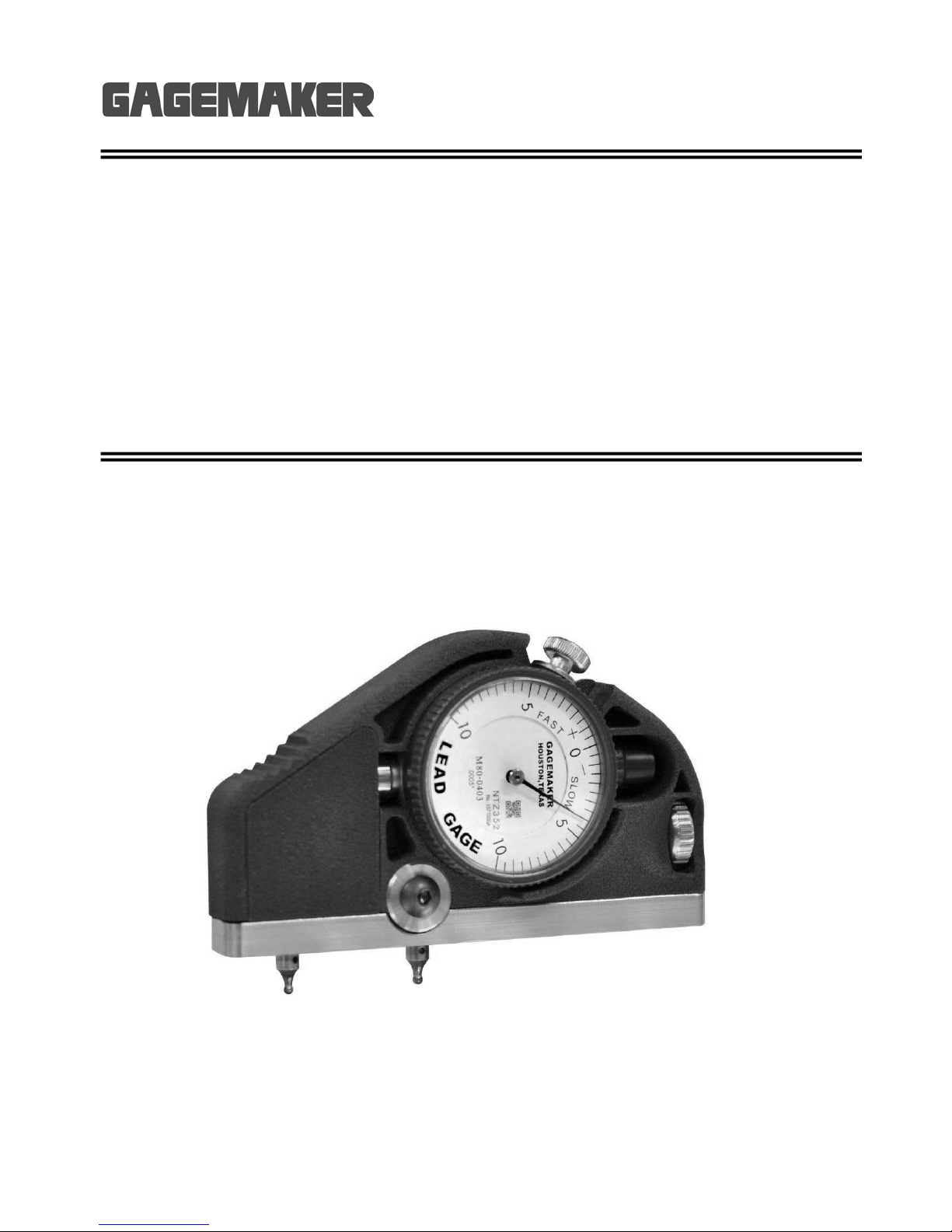
Lead Gage Operation Manual Model LG-6001
Copyright © 2016 Gagemaker. All rights reserved
10
Setup Procedures
Setting Up the Lead Gage
Materials Needed:
Lead gage Calipers
Contact points (2) Paper clip
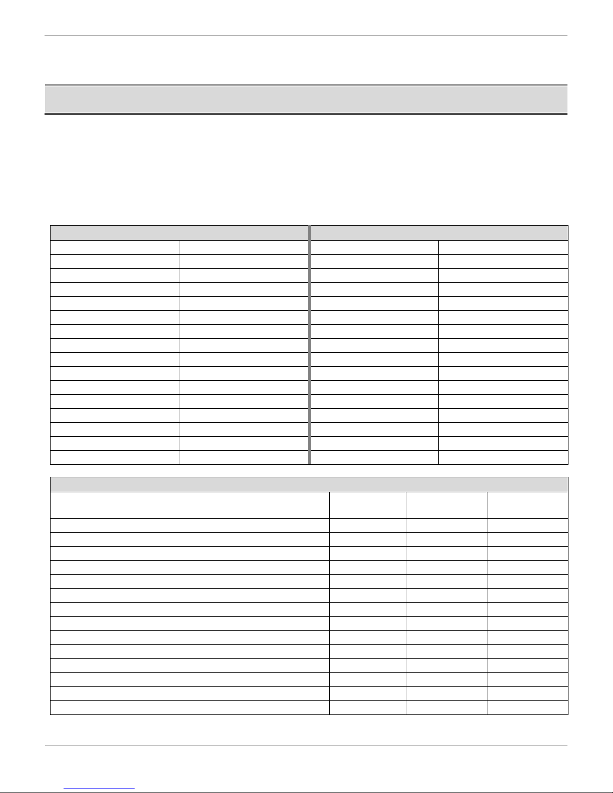
Setting up the lead gage, involves installing the proper size contact points for the application (refer to the
table below for selecting the proper model contact point for ACME, Stub ACME, UN threads or API
threads).
ACME or Stub ACME Threads
1 pitch T531T 1 pitch T562
1.5 pitch T344T 2 pitch T288
2 pitch T266T 3 pitch T188
2.5 pitch T219T 3.5 pitch T188
3 pitch T188T 4 pitch T144
3.5 pitch T144T 4.5 pitch T128
4 pitch T128T 5 pitch T115
5 pitch T105T 5.5 pitch T105
6, 7 pitch T090T 6 pitch T096
8 pitch T062T 8 pitch T072
10 pitch T050T 10 pitch T057
12 pitch T041T 12 pitch T050
14 pitch T041T 14 pitch T041
16 pitch T032T 16 pitch T041
18 pitch T032
Connection Type Point
Diameter Thread Pitch Contact Point
Model Number
All Hughes H-90 0.200” 3 ½ T200
API Rotary Shouldered Connections 0.144” 4 T144
API Rotary Shouldered Connections
API Rotary Shouldered Connections
Truncated for Extreme Line 0.105” 5 ½ T105T
API Rotary Shouldered Connections
API Tubing, Casing and Line Pipe 0.072” 8 T072
Buttress Casing - Lead 0.062” 5 T062
API Line Pipe 0.050” 11 ½ T050
API Line Pipe 0.041” 14 T041
API Line Pipe 0.021” 27 T021